Transcription
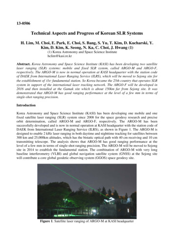
13-0506Technical Aspects and Progress of Korean SLR SystemsH. Lim, M. Choi, E. Park, E. Choi, S. Bang, S. Yu, T. Kim, D. Kucharski, Y.Kim, D. Kim, K. Seong, N. Ka, C. Choi, J. Hwang (1)(1) Korea Astronomy and Space Science Institutehclim@kasi.re.krAbstract. Korea Astronomy and Space Science Institute (KASI) has been developing two satellitelaser ranging (SLR) systems: mobile and fixed SLR system, called ARGO-M and ARGO-F,respectively. The ARGO-M is now in normal operation at KASI headquarter with the station codeof DAEK from International Laser Ranging Service (ILRS), which will be moved to Sejong site forthe establishment of the fundamental station. So Korea became the 25th country that operates SLRsystem in support of the international laser tracking network. The ARGO-F will be developed in2016 and then installed at the Gamak site which is about 150km far from Sejong site. It wasdemonstrated that ARGO-M has good ranging performance at the level of a few mm in terms ofsingle-shot ranging precision.IntroductionKorea Astronomy and Space Science Institute (KASI) has been developing one mobile and onefixed satellite laser ranging (SLR) system since 2008 for the space geodesy research and preciseorbit determination, called ARGO-M and ARGO-F, respectively. The ARGO-M has beensuccessfully developed and is now in normal operation at KASI headquarter with the station code ofDAEK from International Laser Ranging Service (ILRS), as shown in Figure 1. The ARGO-M isdesigned to enable 2 kHz laser ranging in both daytime and nighttime tracking for satellites between300 km and 25,000km altitudes, which has the bistatic optical path with 40 cm receiving and 10 cmtransmitting telescope. The analysis shows that ARGO-M has good ranging performance at thelevel of a few mm in terms of single-shot ranging precision. The ARGO-M will be moved to Sejongsite in 2014 to establish the fundamental station. The combination of ARGO-M with very longbaseline interferometry (VLBI) and global navigation satellite system (GNSS) at the Sejong sitewill contribute a core global geodetic observing system (GGOS) space geodesy site.Figure 1. Satellite laser ranging of ARGO-M at KASI headquarter
The ARGO-F has the common coude optical path with 100 cm telescope, whose ranging precisionis required to be less than 3mm for normal point (NP) of LAGEOS satellite. It is designed to be afully automatic remote operation. The ARGO-F has two functions: satellite laser ranging up togeostationary satellites and space objects imaging using an adaptive optics. Additionally, it will beupgraded to space debris laser ranging using high power laser in 2017. The ARGO-F is now in thephase of system design, which will be developed in the first quarter of 2016 through cooperation ofa foreign institute.Technical Aspects of ARGO-MThe ARGO-M consists of six sub-systems: optical system, optoelectronic system, laser system,tracking mount, operation system and dome. In addition, it has also the laser hazard radar tomonitor airplanes, the ground target to calculate the system delay, and weather sensors to correctthe atmospheric delay and refraction based on Marini-Murray model (Marini and Murray, 1973).The ARGO-M has three rooms: laser, operation and accessory room. There are the steel pier oftracking mount, laser, optical table and ground target pillar in the laser room. The operation systemand many electronics including event timer, tracking mount servo system are installed in theoperation room. Two air conditioner are installed to maintain a constant room temperature in bothlaser and operation room for normal operation of laser and electronics. There are a uninterruptedpower supply (UPS), power distribution unit and surge protection device in the accessory room. Thesystem configuration of ARGO-M is shown in Figure 2 and the internal structure in Figure 3.Figure 2. System configuration of ARGO-MThe ARGO-M is designed to enable 2 kHz laser ranging in both daytime and nighttime tracking forsatellites equipped with laser retro-reflector array (LRA) at altitude of 300 to 25,000 km. It has thebistatic optical path employing the 40 cm receiving and 10 cm transmitting telescopes. For thedaytime tracking and 2 kHz laser ranging, the ARGO-M is adapting the event timer, the spatial andnarrow band-pass filter and the high energy laser with 2.5 mJ energy per pulse at 2 kHz. The laserbeam size is expanded 15 times by two beam expanders in the transmitting optics and 3 times in thetransmitting telescope. The beam divergence is adjusted in the range of 5 to 200 arcsec by changingthe position of concave in the transmitting telescope, which is depending on the satellite altitude.
The receiving telescope is a Ritchy-Chretien optical system where the primary and secondarymirrors are hyperboloids. The system F ratio (aperture to focal length ratio) is F/10.3 and theprimary mirror has 1.5 of F ratio. The iris, spatial filter has three kinds of field of views (FoV, 30",150" and 300") and one blocked spatial filter used for sun shutter to protect C-SPAD against directsun light: 30" for daytime, 150" for dawn and twilight, and 300" for nighttime observation. The CSPAD is made by Peso Consulting in Austria is used, and PCO 1600 and Watec WAT-120Nmodels are also used for daytime and nighttime cameras, respectively.Figure 3. Internal Structure of ARGO-M, laser room(left), operation room(middle), accessoryroom(right)In the satellite ranging, the optoelectronic controller generates laser fire command and range gate(RG) for C-SPAD activity based on the predicted time of flight (TOF) and start signals information,which is implemented by field programming gate array (FPGA) board for the fast functionaloperation. But in the case of ground calibration, it generates laser fire command and RG directlywithout any information of TOF and start signals because the stop pulse arrives at the C-SPADearlier than the RG signal due to short distance of the ground target. The ARGO-M uses the EventTimer A033-ET(Institute of Electronics and Computer Science, Latvia) which records the epochs ofstart and stop signals and then puts them into buffer for the implementation of kHz laser ranging.The laser system is required to be compact size, small pulse width and kHz repetition rate forARGO-M as well as high energy per pulse in order to increase the link budget (Lim et al. 2010). Sothe ARGO-M uses RGL-532 model(Photonics Industries, USA) for laser system. The operationsystem monitors the status of five sub-systems, equipment and sensors. In addition, it controls theenvironmental factor and sub-systems for observation, and generates the final observation productssuch as raw data and NP data through polynomial fitting. The interface diagram of operation systemis shown in Fig. 4. The detailed description of optical and optoelectronic system are given by twoliteratures (Nah et al. 2013, Lim et al. 2011). The major specifications of ARGO-M and ARGO-Fare shown in Table 1.Analysis of ARGO-M PerformanceIn general, SLR data quality is evaluated based on six performance parameters: average single-shotranging precision of ground calibration, Starlette and LAGEOS satellite, average NP rangingprecision of LAGEOS satellite, and short and long term bias stability. The first three parameters areobtained from NP generation during the last quarter but the last three are based on rapid orbitalanalysis results from various Analysis Centers (ACs), during the last quarter for the fourth and fifthparameters and the past year for the last one. The short term stability is computed as the standarddeviation of the pass-by-pass range biases but the long term stability is the standard deviation of the
monthly range bias estimates. In this study, three average single-shot ranging precision are used toevaluate ARGO-M measurement data quality because other performance parameters are computedby five ACs and will be given on ILRS website after several months. To compare data quality ofARGO-M with ILRS stations, measurement data set is October 1-30, 2013 for ARGO-M and thethird quarter for ILRS stations.Figure 4. Interface diagram of ARGO-M operation systemTable 1. Specifications of ARGO-M and ARGO-FItemParameterOptical pathRx and Tx telescopePrimary mirror F-ratioTelescopeTransmit beam divergenceMax. slew rateDetectorLaserOthersTracking & Pointing accuracyTypeQuantum efficiencyWavelengthPulse energy or PowerPulse widthRepetition rate of OperationBeam diameter @ Tx telescopeTiming systemAircraft detection typeARGO-MBistatic40/10 cm1.55 200 arcsec20 deg/sec (Az)10 deg/sec (El) 5 arcsecC-SPAD20%532 nm2.5mJ @2 kHz50 ps2 kHz7.5 cmEvent timerRadarARGO-FCommon Coude 100 cm30 deg/sec (Az)15 deg/sec (El) 1 arcsecMCP-PMT or C-SPAD532 nm 1W 20 ps 50 cmEvent TimerRadarThe ARGO-M uses only one ground target with short distance of about 100 cm from the virtualreference point of telescope for ground calibration. The ground target is installed inside the dome,which consists of prism, diffuser and neutral density filter to decrease laser power to C-SPAD. Thedensity filter was selected so that the return rate is about 30% with 300 arcsec FoV of spatial filter
in the nighttime observation. In the case of ARGO-M, the ground calibration is fulfilled beforesatellite tracking because it is required to be done before and after every satellite pass. Thecalibration correction depends not only on distance between the virtual reference point and theground target, but also on the atmospheric condition such as temperature, press and humidity. In theprocess of sigma filtering, sigma value of 2.2 is used to compute calibration correction becauseARGO-M is 2 kHz laser ranging system using C-SPAD detector. In the ground ranging, the averagesingle-shot ranging precision is 5.7 mm for ARGO-M and 7.9 mm for mean of 28 ILRS stationsfrom global report cards issued quarterly by the ILRS Central Bureau.Figure 5. Single-shot ranging result of ground calibrationThere are many satellites equipped with LRA for geodesy, remote sensing, navigation and scientificexperiments. Starlette and LAGEOS satellites have also spherical shape covered with retroreflectors for geodesy research. SLR data quality depends on the retro-reflectors characteristics andthe accuracy to which the satellite center of mass is measured or modeled as well as SLR systemperformance. The single-shot ranging precisions are analyzed for Starlette and LAGEOS satellite.In the process of sigma filtering to generate NP data, sigma value is same as ground target ranging.In the Starlette satellite ranging, the average single-shot ranging precision is 9.1 mm for ARGO-Mand 12.2 mm for mean of 33 ILRS stations. In the case of LAGEOS satellite, the ARGO-M has10.3 mm of ranging precision and 32 ILRS stations have 12.9 mm as mean. These average singleshot ranging precision of ILRS stations is also given in global report cards.Figure 6. Single-shot Ranging result of Starlette satellite
Figure 7. Single-shot Ranging result of LAGEOS satelliteSummaryKorea Astronomy and Space Science Institute (KASI) has been developing two SLR systems since2008 for the space geodesy research and precise orbit determination: ARGO-M and ARGO-F. TheARGO-M is now in normal operation at KASI headquarter, which will be moved to Sejong site forthe establishment of fundamental station. The ARGO-F is now in the phase of system design andwill be installed at Gamak site in the first quarter of 2016, which will be upgraded to space debrislaser ranging using high power laser in 2017. It was demonstrated that ARGO-M has good rangingperformance at the level of a few mm in terms of single-shot ranging precision. The results showARGO-M has good performance: 5.7 mm for ground calibration, 9.1 mm for Starlette satelliteranging and 10.3 mm for LAGEOS satellite ranging. The ARGO-M will be upgraded into 10 kHzlaser ranging in 2014 with more compact operation system and new optoelectronic controller, whichleads more returned signals and then increase ranging precision. With the high technologyincorporated into ARGO-M, it is expected that ARGO-M plays an important role in thedevelopment of laser ranging data products.AcknowledgmentsThis study was supported by the Korea Astronomy and Space Science Institute through the SLRsystem development project funded by the Ministry of Science, ICT and Future Planning (MSIP).ReferencesLim, H., Seo, Y., Na, J., Bang, S., Lee, J., Cho, J., Park, J. and Park, J., Tracking CapabilityAnalysis of ARGO-M Satellite Laser Ranging System for STSAT-2 and KOMPSAT-5,Journal of Astronomy and Space Sciences, Vol. 27, No. 3, 2010Lim, H., Bang, S., Yu, S., Seo, Y., Park, E., Kim, K., Nah, J., Jang, J., Jang, B., Park, J. and Park, J.,Study on the Optoelectronic Design for Korean Mobile Satellite Laser Ranging System,Journal of Astronomy and Space Sciences, Vol. 29, No. 2, 2011Marini, W. and Murray, W., X-591-73-351 report, NASA GSFC, 1973Nah, J., Jang, J., Jang, B., Han, I., Han, J., Park, K., Lim, H., Yu, S., Park, E., Seo, Y., Moon, I.,Choi, B., Na, E. and Nam, U., Development of Optical System for ARGO-M, Astronomy andSpace Sciences, Vol. 30, No. 1, 2013
operation room. Two air conditioner are installed to maintain a constant room temperature in both laser and operation room for normal operation of laser and electronics. There are a uninterrupted power supply (UPS), power distribution unit and surge protection device in the accessory room. The