Transcription
Planning Factors (Link Budget)ATSC Mobile DTVWhitepaperIn the 1990’s the FCC defined the planning factors for ATSC DTVservice, a link budget containing these planning factor values wasthen used to calculate the minimum field strength that had to existat a ATSC receiver antenna to enable reception. The FCC used theF (50, 90) propagation curves to find the distance (miles) to thiscalculated minimum field strength given the transmit frequency,antenna height, and ERP, this distance from the transmit antennadefined the coverage area of the DTV station. There currently are nopublished planning factors or a link budget for the new ATSC MobileDTV service.Mike Simon11.2010-1WhitepaperTherefore, this white paper develops planning factors for severalclasses of ATSC Mobile DTV service. A link budget is used tocalculate the minimum field strengths, these are then normalized.The FCC F (50, 90) curves are used to find the distance (miles) tothis minimum field strength contour (ATSC Mobile DTV). A modelUHF DTV station (615 Mhz) with an ERP 1,000 kW, 1,200 HAAT isassumed to carry both normal (A/53) and mobile (A/153) services.A comparison is made of the predicted coverage area for this modelstation broadcasting both fixed (A/53) and mobile (A/153) services.1
ContentsIntroduction.3A/53 Planning Factors .3FCC F(50, 90) Propagation Curves.4Mobile Environment .4A/153 Planning Factors .5A/153 Link Budget.6Conclusion.8References .8R&S ATSC Mobile DTV Solutions.9Contacting Rohde & Schwarz. 9v1Rohde & Schwarz Planning Factors (Link Budget) ATSC Mobile DTV2
Figures and TablesFigure 1 A/53 Fixed Propagation Model.4Figure 2 FCC F (50, 90) Propagation Curve.5Figure 3 Model of Mobile Environment.6Figure 4 A/53 and a/153 Field Strengths (dBu).8Figure 5 FCC F (50, 90) Distance Miles to Contour.8Table 1 FCC A/53 Planning Factors.5Table 2 Class of Mobile/ Handheld Service.6Table 3 A/153 C/N Lab Tests CRC.6Table 4 Receiver Antenna Gain.7Table 5 Penetration Loss (Lp) Vehicle and Building .7Table 6 Receiver Noise Figure (F).7Table 7 Thermal Noise 6 MHz (Nt).7Table 8 Antenna Loss Height (Lh) @ 1.5 meter .7Table 9 Correction Factor FCC (Kd) Broadband Signal.7Table 10 Quality Coverage Correction Coefficient (Qc).7Table 11 Field Strength Variation (Fv) Correction Factor .7Table 12 Other Losses (Lo).7Table 13 (Emed) Minimum Median Field Strength (dBu) .8v1Rohde & Schwarz Planning Factors (Link Budget) ATSC Mobile DTV3
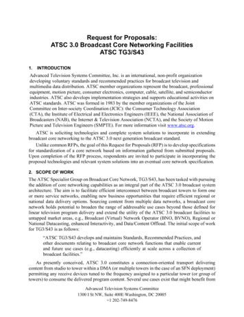
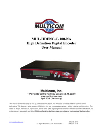
Introduction: ATSC Mobile DTVIntroductionTo get a first approximation of the servicearea an ATSC UHF DTV station can expectfor A/153mobile and handheld services, thecurrent ATSC planning factors1 for (A/53 fixedservice) are reviewed. The A/53 planningfactors allow the development of a link budget,resulting in the calculated minimum fieldstrength needed for service per the FCC rules.For all A/53 ATSC digital television stations,the calculated minimum fieldstrength value is used with the FCCpropagation curves derived for 50%of locations and 90% of the time asdescribed in Section 73.699 of FCCrules. The minimum field strengthcontour is considered the DTVnoise limited coverage area bythe FCC. The FCC curves assumea given ERP and Antenna HAAT.(Height Above Average Terrain)The F (50, 90) distance (miles) to the minimumfield strength contour is independent of theterrain. The minimum field strength contour(distance) is then used as the area withinwhich to calculate potential DTV service usingthe Longley-Rice terrain-dependent predictionmethod described in FCC OET Bulletin number69.The A/153 planning factors2 are developed,used to calculate the minimum medianfield strength for different classes of A/153reception, Mobile (vehicle), HandheldSee FCC OET-69 Bulletin Table 3 Planning Factors OET --BulletinsOn-line1The A/153 planning factors are based on the experience of thewireless industry and use CRC lab data from the LG prototype(FPGA) A/153 receiver2v1(pedestrian), both outdoors and inside vehiclesand building structures. The distance (miles) tothe minimum median field strength contour isfound by using the FCC F (50, 90) curves, andusing a correction factor (Lh), antenna heightof 1.5 meter for A/153. The coverage areas(A/53, A/153) for a UHF DTV station using a1,000 kW ERP and HAAT 1,200 ft. is presented.A terrain-dependent prediction method (notconsidered) would predict (considering terrain)a smaller service area than the coverage areaFigure 1 A/53 Fixed Propagation Modelpredicted using F (50, 90) curves. Therefore,the A/153 coverage presented is consideredgenerous.A/53 Planning FactorsFigure 1 shows the A/53 fixed propagationmodel. The receiver is assumed to have a directline of sight (LOS) path. The FCC planningfactors for UHF assume a receiver Noise Figure(F) of 7 dB. The thermal noise (Nt) in 6 MHzchannel is -106.2 dBm. The receiver minimumC/N is 15.2 dB. The line loss (L) from antennato receiver is 4 dB. The dipole conversionfactor (FCC Kd) is 130.8 dB, converts receivedRohde & Schwarz Planning Factors (Link Budget) ATSC Mobile DTV 4
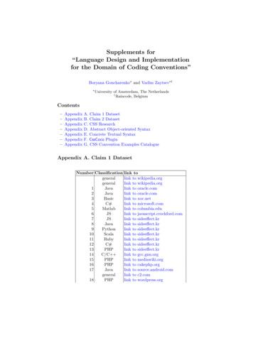
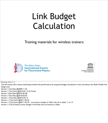
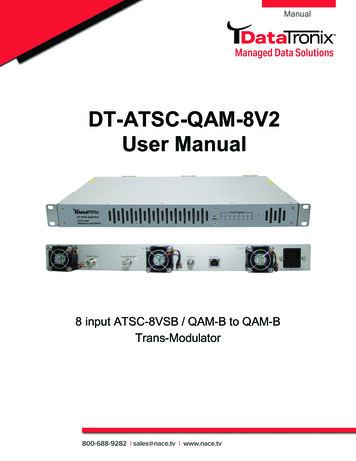
A/53 Planning Factorspower dBm to field strength in dBu. (dBmicrovolts/ meter) The antenna gain (G) is 10dBi.ParameterUHFGeometric Mean Frequency615 MHzReceiver Noise Figure (F)7 dBNoise 6 MHz (Nt)-106.2 dbmNoise Rx Input-99.2 dBmMin required (C/N)15.2 dBMin Signal Rx Input-84.0 dBmLine Loss (L)4 dBMin Signal Power Antenna-80 dBmDipole Conversion Factor(FCC Kd)130.8 dBMin Field Strength dBu50.8 dBuGain Antenna (G)10dBiMin. Field Strength40.8 dBuTable 1 FCC A/53 Planning FactorsIn table 1 the FCC ATSC A/53 minimum fieldstrength (@ 615 MHz) is 40.8 dBu. To calculatethe minimum field strength (dBu) equation 1is used:MinFieldStrength (dBu) F Nt c/n L Kd -Gv1The F (50, 90) propagation curve in figure 2 isfor UHF and an ERP 1,000 kW. Along the Y axisis field strength (dBu), along the horizontal axisis distance (miles). Locate 40.8 dBu on the yaxis and follow this across plot (dash line) untilit intersects with the antenna height. (HAAT)For example a DTV station with an HAAT of1200 ft. has a distance of (64.5 miles) to the40.8 dBu contour according to the FCC.3 Note:FCC F(50, 90) curves for other common ERPvalues can easily be generated. In the nextsection the planning factors and a link budgetfor several different A/153 classes of mobileservice will be developed. The minimum fieldstrength calculated is then used with the FCC F(50, 90) curve, (1,000 kW ERP, 1,200 ft.) to finddistance to the minimum median field strengthcontours (dBu).Mobile EnviornmentFigure 3 is the model for the A/153 mobileenvironment. The mobile receiver antenna isassumed to be only 1.5 meters above ground.It may be mounted on a moving vehicle orin the case of a handheld receiver may betelescopic or embedded inside the receiver.The mobile and handheld antenna at 1.5meters has very little clearance to the groundor to close by objects, so these reflectingsurfaces in the vicinity of the receive antennaFCCF(50, 90)PropagationCurvesThe FCC usesthe minimumfield strength(40.8 dBu)and its FCCF (50, 90)propagationcurves to findthe distance(miles) to the field strength contour, assuminga 30 ft. receive antenna.3Figure 2 FCC F (50, 90) Propagation aper argues that the FCC planning factors have a shortfall of 8dB-10 dB and are inadequate for DTV service planning. Note: Thispaper adopts some of these recommendations for planning ofA/153.Rohde & Schwarz Planning Factors (Link Budget) ATSC Mobile DTV5
Mobile Enviornmentwill have a substantial influence on thecharacteristics of the propagation path in themobile environment.received signal power to fluctuate due toobjects obstructing the propagation pathbetween transmitter and receiver.F: Doppler - Motion of a receive antenna orreflections from moving objects producesDoppler shifts of incoming RF waves, thisaffects the amplitude of the resulting signal.These factors are accounted for in the labfading used to derive the (C/N) values in table3.A/153 Planning FactorsTable 2 Class of Mobile/ Handheld ServiceFigure 3 Model of Mobile EnvironmentA: Free Space Loss - free space loss assumesa transmit antenna and a receive antenna islocated in an empty space environment.B: Reflection - Reflection occurs when apropagating electromagnetic wave impinges ona smooth surface with very large dimensionscompared to the RF signal wavelength (λ).C: Diffraction - diffraction occurs when thepropagating path between the transmitter andreceiver is obstructed by a dense body withlarge dimensions compared to wavelength λ.Diffraction is a phenomenon that accounts forthe RF energy traveling from transmitter toreceiver without a line-of-sight path.D: Scattering - Scattering occurs when a RFwave impinges on a surface whose dimensionsare on the order of λ or less causing the RFreflected energy to be spread out or scatteredin all directions.ClassEnviornmentCharacteristicsClass APedestrian (outdoor)1.5 M 3 km/hClass B1Pedestrian (indoor)1.5 M 3 km/hClass B2Pedestrian (deepindoor)1.5 M 3 km/hClass CVehicle (roof antenna)1.5 M 120 km/hClass DVehicle (inside)1.5 M 120 km/hTable 2 shows several different classes ofservices considered in the A/153 link budget.Table 3 A/153 C/N Lab Tests CRCEnvironment (C/N)¼ SCCC½ SCCCAWGN3.2 dB7.1 dBPedestrian 3 km/h11.2 dB15.3 dBTU6 120 km/h13 dB17 dBTable 34 shows the (C/N) for 5% error time,these will be used for planning factors.CRC Lab Test Report April 2008, LG FPGA prototype receiver.The data reported for Pedestrian and TU6 (Rayleigh) fading areused for A/153 planning factors4E: Shadowing - shadowing causes thev1Rohde & Schwarz Planning Factors (Link Budget) ATSC Mobile DTV6
A/153 Planning FactorsAntennaGain (G)compared to the 30 ft. assumed in A/53 fixedservice5Handheld (Embedded)-7 dBTable 9 Correction Factor FCC (Kd) Broadband SignalHandheld (Telescopic)-3 dB(FCC Kd)Correction Factor(Kd)Vehicle (Roof Mounted)-2 dB130.8 dB5 dB135.8 dBTable 4 Receiver Antenna GainTable 4 shows antenna gains (G). Atelescopicantenna is assumed in Class (A, B1,B2, and D).Table 5 Penetration Loss (Lp) Vehicle and BuildingPenetration LossLoss (LP)Class D7 dBClass B111 dBClass B217 dBTable 10 Quality Coverage Correction Coefficient (Qc)Table 5 shows the penetration loss (Lp) to beused for reception inside a vehicle or indoors ina building in planning factors.Receiver Noise Figure (F)Table 9 shows correction (5 dB) added to thedipole correction factor (FCC Kd) to correctfor a broadband signal. 6 Note: The (FCC Kd)calculation is for a narrowband signal.-106.2 dBm1.5 M Height10 dBClass A,C,D5.5 dBClass B17.4 dBClass B28.1 dBAll Other LossesLoss Other (Lo)Man-made noise, mismatch,cable, polarization, misc.3 dBA/153 Link BudgetTable 8 shows the Loss (Lh) for areceiver antenna height of 1.5 metersThe minimum median field strength (Emed)can be calculated using equation 2 below:(Lh) dB is added to (Emed) dBu to allow use of the FCC F (50, 90)propagation curves (30 ft. antenna height) to the find the distance(miles) to A/153 See figure 13 for explanation of this correction factorField Strength Variation (Fv)Table 12 shows all other losses considered (Lo)Table 8 Antenna Loss Height (Lh) @ 1.5 meter5Class of ServiceTable 11 shows value (Fv) field strengthvariation to be included in planning factors.Table 7 shows the thermal Noise 6 MHz (Nt),that will be used as a planning factor.dB (Lh)1.28Table 12 Other Losses (Lo)Table 7 Thermal Noise 6 MHz (Nt)Loss HeightAcceptableTable 11 Field Strength Variation (Fv) Correction FactorTable 6 Receiver Noise Figure (F)Thermal Noise 6MHz (Nt)Correction Coefficient 90% locations (Qc)Table 10 shows a correction factor (Qc) formobile reception at 90 % of the locations.6 dBTable 6 shows the Receiver Noise Figure thatwill be used as planning factor.Quality ofCoverageEmed (dBu) F Nt c/n Kd - G La Lp [(Qc)x(Fv)]6v1Shows values for ½ SCCC and ¼ SCCCmodes, both with P 48 bytes RS-CRC Parityfor packet layer FEC7Rohde & Schwarz Planning Factors (Link Budget) ATSC Mobile DTV7
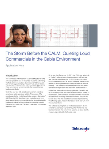
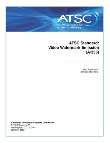
A/153 Link BudgetTable 13 (Emed) Minimum Median Field Strength (dBu)Class of Service¼ SCCC½ SCCCPedestrian Outdoor (A)63 dBu67 dBuPedestrian Indoor (B1)77 dBu81 dBuPedestrian Deep Indoor (B2)84 dBu88 dBuVehicle Roof Antenna (C)62 dBu67 dBuVehicle Inside (D)70 dBu75 dBuTable 13 7shows the A/153 minimum medianfield strength calculated using equation 2rounded to nearest integer dB value.Figure 5 FCC F (50, 90) Distance Miles to Contourindoor telescopic antenna) There is a 47 dBdelta between the FCC A/53 planning factors(fixed service)and Class B2 A/153 (mobile).Figure 4 A/53 and A/153 Field Strengths (dBu)Some of this is due to the planning factorsused for A/53, which assumed an ideal (LOS)propagation model and an AWGN limitedservice. The A/53 planning factors don’t matchthe real world8 but allowed the FCC to moreeasily attempt to replicate the NTSC coveragearea, their goal.Figure 4 shows a plot of the field strengthdBu for both A/53 (fixed) and A/153 (mobile)services. The 40.8 dBu field strength for A/53(fixed) shown is the value calculated usingequation 1. The field strength for each A/153class of service is shown from left to right (A,B1, B2, C, D) for mode ½ SCCC and mode ¼SCCC using values from table 13. The strongestfield strength shown (88 dBu) is for mode½ SCCC, Class B2 pedestrian 3 km/h. (deepNext, we will use the FCC F (50, 90) curvefigure 2, 1,000 kW ERP, 1,200 feet HAAT, tofind the distance (miles) to the field strengthvalues shown in Figure 4. A correction factor(Lh) 10 dB must be added to all the A/153values shown Figure 4. The FCC F (50, 90)curves use empirical field data collected withan antenna at a height of 30 feet. The heightcorrection factor9 (Lh) 10 dB assumes 1.5 meterheight receiving antenna.See “ Planning Factors for Fixed and Portable DTTV Reception byOded Bendov, Yiyan Wu, Charles W. Rhodes and John F.X. .pdfv1TR102327 version 1.41 April 2009 DVB-H implementationGuidelines; table 11.4 Height Loss shows values for differentenvironments in a range 11-22 dB. The 10 dB (Lh) value chosen inthis paper can be considered realistic and maybe conservative.9Rohde & Schwarz Planning Factors (Link Budget) ATSC Mobile DTV8
A/153 Link BudgetThe 65 mile distance for (A/53) fixed is shownin Figure 5, along with the distances to thefield strength contour for all the A/153 (mobile)Class of service. The shortest distance is seenfor the ½ SCCC Class B2 (deep Indoor) at 20miles. The longest distance is for ¼ SCCCClass C (vehicle roof antenna) at 43 miles.Note: the 43 mile distance can be seen on theFCC F (50, 90) curve figure 2, is located at theRadio Horizon.ConclusionThis paper developed the planning factors forseveral classes of ATSC Mobile DTV service.It then normalized the A/153 field strengthscalculated, by applying a correction factor(Lh) antenna height. The FCC F (50, 90) curveswere then used to find the distance (miles)to this field strength contour. The same UHFDTV station (615 MHz) with an ERP 1,000kW, 1,200 HAAT was assumed to carry bothnormal (A/53) and mobile (A/153) services. Acomparison was made of the distances (miles)to get an approximation of the coverage area aDTV station could expect for the new mobile(A/153) services, assuming both pedestrian(handheld) and vehicle reception.To predict the actual A/153 mobile servicearea a terrain-dependent propagation model(Software) would be used to predict serviceat all locations within the F (50, 90) coveragearea. This terrain dependent propagationsoftware would use the A/153 planning factorsand a receiver antenna height of 1.5 meters.There are currently no FCC rules for ATSC Mobile DTV coverageor service prediction.10v1This propagation software in addition toproviding a terrain database may also provideland use databases (building and structures inurban areas) to improve the service locationprediction. The resulting terrain dependentmobile service area would normally be smallerthan the coverage area predicted using theFCC F (50, 90) propagation curves. Therefore,a good first approximation of the ATSC MobileDTV service area can be gleaned using themethods10 described in this paper.ReferencesATSC A/53 Standard Part 2: 2007;http://www.atsc.org/cms/standards/53/a 53Part-2-2007.pdfATSC A/153 Standard Part 2: 2009;http://www.atsc.org/cms/standards/a153/a 153-Part-2-2009.pdfFCC OET Bulletin ogy/Documents/bulletins/oet69/oet69.pdfPlanning Factors for Fixed and PortableDTTVReception; Oded Bendov, Yiyan, Wu,Charles W. Rohdes, John F.X. DVB-H Implementation .V1.4.1.DVBH impl guide.pdfMobile Broadcast Technologies LinkBudgetsBMCO forum (White Paper 2/2009)http://www.bmcoforum.org/index.php?id 256&no cache 1Rohde & Schwarz Planning Factors (Link Budget) ATSC Mobile DTV9
Rohde & Schwarz Mobile DTV SolutionsRohde & Schwarz Mobile DTV SolutionsHeadendThe R&S AEM100 multiplexer for ATSC Mobile DTV service combines thefunctions of IP encapsulation with multiplexing to enable broadcasters to offernew services inside their existing ATSC transport stream. The R&S AVE264mobile TV encoder can be teamed with the R&S AEM100.TransmissionThe R&S Sx800 is a software configurable television exciter that featuresadaptive pre-correction for linear and non-linear distortions. The excitercan be adapted to different operating standards and modes, including ATSCMobile DTV and Single Frequency Networks (SFN). Exciter retrofit packagesare available to allow use of the R&S Sx800 in transmitters produced by othermanufacturers.TransmissionThe R&S Nx8000 family of transmitters is comprised of both liquid(R&S NV8600) and air-cooled (R&S NV8300/R&S NW8200) transmittersfor high and medium power applications. All R&S Nx8000s feature theR&S Sx800 television exciter for excellent signal performance and flexibilityacross both VHF and UHF. The R&S Nx8000 transmitters are very energyefficient with redundant architecture for maximum reliability.TransmissionThe R&S SCx8000 is the ultimate in efficient design. It consists of thenew exciter R&S SX801 and up to two amplifiers with integrated cooling,combiner and splitter. All major TV standards, including ATSC Mobile DTV aresupported with the same hardware. Innovative redundancy concepts make thesystem highly reliable. Its modular design enables the system to be a standalone device, in existing racks and outdoor cabinets.Test & MeasurementThe R&S ETL TV Analyzer performs 8VSB testing and optional MPEGmonitoring in a single unit. It combines TV test receiver and spectrum analyzerfunctionality while providing high measurement accuracy. Both digital andanalog TV standards can be integrated in a single instrument. The R&S ETL TVAnalyzer uses realtime demodulation throughout.v1Rohde & Schwarz Planning Factors (Link Budget) ATSC Mobile DTV 10
Contacting Rohde & SchwarzContacting Rohde & SchwarzWalt GumbertNational Account Manager, Transmitter SystemsRohde & Schwarz, Inc.8661A Robert Fulton DriveColumbia, MD 21046724-693-8171 (Office)724-312-7700 (Cell)410-910-7801 (Fax)e-mail: Walt.Gumbert@RSA.rohde-schwarz.comDave BencoNational Key Account ManagerTransmitter SystemsRohde & Schwarz, Inc.8661A Robert Fulton DriveColumbia, MD 21046724-852-1332 (Office)724-470-4440 (Cell)410-910-7801 (Fax)e-mail: Dave.Benco@rsa.rohde-schwarz.comMike SimonAdvanced Technologies ManagerBroadcast DivisionRohde & Schwarz, Inc.8661-A Robert Fulton DriveColumbia MD. 21046e-mail: Mike.Simon@rsa.rohde-schwarz.comv1Rohde & Schwarz Planning Factors (Link Budget) ATSC Mobile DTV 11
About Rohde & SchwarzRohde & Schwarz is an independent group ofcompanies specializing in electronics. It is a leadingsupplier of solutions in the fields of test andmeasurement, broadcasting, radiomonitoring andradiolocation, as well as secure communications.Established 75 years ago, Rohde & Schwarz has aglobal presence and a dedicated service networkin over 70 countries. Company headquarters are inMunich, Germany.Regional contactEurope, Africa, Middle East 49 1805 12 42 42* or 49 89 4129 137 74customersupport@rohde-schwarz.comNorth America1-888-TEST-RSA .comLatin America Asia/Pacific 65 65 13 04 88customersupport.asia@rohde-schwarz.comThis whitepaper and the suppliedprograms may only be used subject to the conditionsof use set forth in the download area of the Rohde &Schwarz website.Rohde & Schwarz GmbH & Co. KGMühldorfstraße 15 D - 81671 MünchenPhone 49 89 4129 - 0 Fax 49 89 4129 – 13777www.rohde-schwarz.com
The data reported for Pedestrian and TU6 (Rayleigh) fading are used for A/153 planning factors. 7 A/153 Planning Factors v1 Rohde & Schwarz Planning Factors (Link Budget) ATSC Mobile DTV Antenna Gain (G) Handheld (Embedded) -7 dB Handheld (Telescopic) -3 dB Vehicle (Roof Mounted) -2 dB Table 4 shows antenna gains (G). A