Transcription
ATSC A/335:2016Video Watermark Emission20 September 2016ATSC Standard:Video Watermark Emission(A/335)Doc. A/335:201620 September 2016Advanced Television Systems Committee1776 K Street, N.W.Washington, D.C. 20006202-872-9160i
ATSC A/335:2016Video Watermark Emission20 September 2016The Advanced Television Systems Committee, Inc., is an international, non-profit organizationdeveloping voluntary standards and recommended practices for digital television. ATSC memberorganizations represent the broadcast, broadcast equipment, motion picture, consumer electronics,computer, cable, satellite, and semiconductor industries. ATSC also develops digital televisionimplementation strategies and supports educational activities on ATSC standards. ATSC wasformed in 1983 by the member organizations of the Joint Committee on InterSociety Coordination(JCIC): the Electronic Industries Association (EIA), the Institute of Electrical and ElectronicEngineers (IEEE), the National Association of Broadcasters (NAB), the National CableTelecommunications Association (NCTA), and the Society of Motion Picture and TelevisionEngineers (SMPTE). For more information visit www.atsc.org.Note: The user's attention is called to the possibility that compliance with this standard mayrequire use of an invention covered by patent rights. By publication of this standard, no positionis taken with respect to the validity of this claim or of any patent rights in connection therewith.One or more patent holders have, however, filed a statement regarding the terms on which suchpatent holder(s) may be willing to grant a license under these rights to individuals or entitiesdesiring to obtain such a license. Details may be obtained from the ATSC Secretary and the patentholder.Implementers with feedback, comments, or potential bug reports relating to this document maycontact ATSC at https://www.atsc.org/feedback/.Revision HistoryVersionDateCandidate Standard approvedStandard approvedReference [2] updated to point to the published version of A/336:201730 November 201520 September 201627 February 2017ii
ATSC A/335:2016Video Watermark Emission20 September 2016Table of Contents1.SCOPE .51.11.22.55REFERENCES .52.12.23.Introduction and BackgroundOrganizationNormative ReferencesInformative References55DEFINITION OF TERMS .63.13.2Compliance NotationTreatment of Syntactic Elements3.2.1Reserved Elements3.3Acronyms and Abbreviation3.4Terms3.5Extensibility6666674.SYSTEM OVERVIEW .75.SPECIFICATION .105.15.25.35.45.5Run-In PatternWatermark Data SymbolsSpatial Redundancy1X Data Rate Video Watermark2X Data Rate Video Watermark1011111112ANNEX A : IMPLEMENTATION OF THE 1X WATERMARK DETECTOR .13A.1A.2OverviewDescription of Algorithm1313iii
ATSC A/335:2016Video Watermark Emission20 September 2016Index of Figures and TablesFigure 4.1 Marked video frame example.Figure 4.2 Luma encoding – 2X System with 8-bit video.Figure 4.3 Luma encoding – 1X System with 8-bit video.Figure A.2.1 Example count of samples with a given value of luma.891013Table 5.1 Horizontal Pixels per SymbolTable 5.2 Luma Value Encodings for 1X SystemTable 5.3 Luma Value Encodings for 2X System111212iv
ATSC A/335:2016Video Watermark Emission20 September 2016ATSC Standard:Video Watermark Emission1. SCOPEThis document specifies the emission format for video watermarks for use within ATSC 3.0broadcasts.1.1Introduction and BackgroundThe video watermark technology described in this document provides the capability to robustlyembed ancillary data in the transmitted pixels of a video signal. It is intended to provide a datapath for its ancillary data payload that can readily survive changes in video compression data rate,transcoding to other video compression codecs and delivery over legacy consumer HDMIinterfaces. It is not intended to be a tamper-resistant or indelible watermark and it may bedeliberately obliterated by an intermediary. Emission by a broadcaster of the video watermark isoptional.This video watermark emission technology is used to deliver the payload data described inATSC A/336 [2].1.2OrganizationThis document is organized as follows: Section 1 – Scope and introduction. Section 2 – Lists normative references and informative documents. Section 3 – Provides a definition of terms, acronyms, and abbreviations for this document. Section 4 – System overview Section 5 – Specification of the video watermark emission format Annex A – Receiver guidelines for adapting to flexible modulation of the video watermark2. REFERENCESAll referenced documents are subject to revision. Users of this Standard are cautioned that newereditions might or might not be compatible.2.1Normative ReferencesThe following documents, in whole or in part, as referenced in this document, contain specificprovisions that are to be followed strictly in order to implement a provision of this Standard.[1] IEEE: “Use of the International Systems of Units (SI): The Modern Metric System,” Doc. SI10, Institute of Electrical and Electronics Engineers, New York, N.Y.2.2Informative ReferencesThe following documents contain information that may be helpful in applying this Standard.[2] ATSC: “ATSC Standard: Content Recovery in Redistribution Scenarios,” Doc. A/336:2017,Advanced Television Systems Committee, Washington, D.C., 24 February 2017.[3] SMPTE: “1920 x 1080 Image Sample Structure, Digital Representation and Digital TimingReference Sequences for Multiple Picture Rates,” Doc. ST 274M-2008, Society of MotionPicture and Television Engineers, White Plains, NY, 29 January 2008.5
ATSC A/335:2016Video Watermark Emission20 September 20163. DEFINITION OF TERMSWith respect to definition of terms, abbreviations, and units, the practice of the Institute ofElectrical and Electronics Engineers (IEEE) as outlined in the Institute’s published standards [1]shall be used. Where an abbreviation is not covered by IEEE practice or industry practice differsfrom IEEE practice, the abbreviation in question will be described in Section 3.3 of this document.3.1Compliance NotationThis section defines compliance terms for use by this document:shall – This word indicates specific provisions that are to be followed strictly (no deviation ispermitted).shall not – This phrase indicates specific provisions that are absolutely prohibited.should – This word indicates that a certain course of action is preferred but not necessarilyrequired.should not – This phrase means a certain possibility or course of action is undesirable but notprohibited.3.2Treatment of Syntactic ElementsThis document contains symbolic references to syntactic elements used in the audio, video, andtransport coding subsystems. These references are typographically distinguished by the use of adifferent font (e.g., restricted), may contain the underscore character (e.g., sequence end code) andmay consist of character strings that are not English words (e.g., dynrng).3.2.1Reserved ElementsOne or more reserved bits, symbols, fields, or ranges of values (i.e., elements) may be present inthis document. These are used primarily to enable adding new values to a syntactical structurewithout altering its syntax or causing a problem with backwards compatibility, but they also canbe used for other reasons.The ATSC default value for reserved bits is ‘1.’ There is no default value for other reservedelements. Use of reserved elements except as defined in ATSC Standards or by an industrystandards setting body is not permitted. See individual element semantics for mandatory settingsand any additional use constraints. As currently-reserved elements may be assigned values andmeanings in future versions of this Standard, receiving devices built to this version are expectedto ignore all values appearing in currently-reserved elements to avoid possible future failure tofunction as intended.3.3Acronyms and AbbreviationThe following acronyms and abbreviations are used within this document.ATSC – Advanced Television Systems CommitteeHDMI – High-Definition Multimedia InterfaceHDTV – High-Definition TelevisionPAM – Pulse-Amplitude ModulationSMPTE – Society of Motion Picture and Television Engineers3.4TermsThe following terms are used within this document.reserved – Set aside for future use by a Standard.6
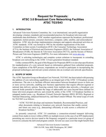
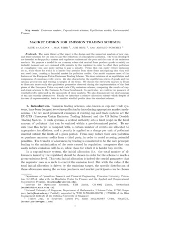
ATSC A/335:20163.5Video Watermark Emission20 September 2016ExtensibilityThe video watermark emission format described in the present standard may coexist with, or bereplaced by, future video watermark systems that employ different methods for embedding datainto the video signal. Signaling of non-backwards-compatible watermark systems that use the firstline of active video would employ a different value for the run-in pattern described in Section 5.1.4. SYSTEM OVERVIEWThe video element of a broadcast program can encode a data stream that may be recovered fromuncompressed video by the receiver. An ATSC 3.0 receiver that is receiving video via an HDMIinterface can use this data stream for a variety of purposes, including hybrid (broadband) deliveryof program elements such as those needed to support interactivity, dynamic ad replacement,service usage monitoring, and content identification.The video watermarking technology specified herein involves modulation of the lumacomponent of video within the top two lines of active video in each video frame. Two encodingoptions are offered, one providing a watermark payload of 30 bytes per video frame (a “1X”version), and the second “2X” version offering double that capacity.Visibility of this video watermark is not anticipated to be an issue because ATSC 3.0-awarereceivers are expected to be designed with the knowledge that the top two lines of active videomay include this watermark, and will thus avoid displaying (by any means desired). The majorityof HDTV display systems in use at the time of publication operate by default in an “overscan”mode in which only the central 95% of video lines are displayed. Thus, if watermarked video isdelivered to a non-ATSC 3.0-aware receiver, the watermark would not normally be seen.The 1X version of the watermark encodes the payload data using luma values of black and adark gray, which renders the watermark unobtrusive even if the display happens to present all 1080lines of an HD image. The choice between larger payload and much-reduced visibility can be madeby the broadcaster.Figure 4.1 depicts one frame of marked video. The first portion of the top two lines of the1080x1920 image are expanded to show the watermark. At the top, an example of the 2X versionis shown and just below it, the 1X version. As shown, each group of 8 horizontal pixels representsan encoded data symbol. In the 2X version, each symbol represents two bits, while in the 1Xversion, each symbol represents one bit. In both cases, the lowest encoded value is encoded withthe lowest (darkest) luma value. While in 8-bit video encoding, value 16 is specified as “black” inSMPTE ST 274M [3], certain values below black are specified for use in this application.7
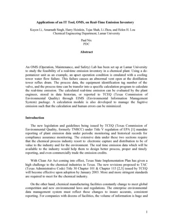
ATSC A/335:2016Video Watermark Emission20 September 2016Figure 4.1 Marked video frame example.Figure 4.2 shows the full range of luma values on the Y-axis for 8-bit video encoding and therange of black to white as defined in SMPTE ST 274M [3] of 16 to 235. As shown, for the 2Xsystem, four levels of luma are used for the encoding, the black and white levels as well as twointermediate shades of gray (levels 89 and 162).8
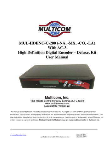
ATSC A/335:201620 September 2016Video Watermark Emission255“white”16Sym. value 3Detect 3212.5Encoded Luminance Value (8-bit)235162Sym. value 2Detect 2127.589Sym. value 1Detect 142.5“black”Sym. value 0Detect 00Figure 4.2 Luma encoding – 2X System with 8-bit video.Modulation levels for the 1X system are flexible to allow the broadcaster to set the desiredbalance between visibility and robustness. The luma level for the “0” value of the symbol is set at4 (for 8-bit video encoding), but the luma value used for the “1” value may be set to any value inthe range 40 to 100. The receiver is expected to take note of the modulation value in use and set aslicing level as appropriate. Figure 4.3 depicts the two cases on the extremes of this range. On theleft, the modulation levels are 4 and 40, and the receiver sets an optimum slicing level of 22. Onthe right, the modulation levels are 4 and 100, and the receiver sets an optimum slicing level of 52.An algorithm that receivers may use to determine the optimum slicing level is given in Annex A.9
ATSC A/335:201620 September 2016Video Watermark Emission255“white”200Encoded Luminance Value (8-bit)235Detect 1Sym. value '1' 10080Detect 1Sym. value '1' 401622“black”Sym. value '0' 40Detect 0Case 1:Modulationvalues (4,40)52Detect 0Sym. value '0' 4Case 2:Modulationvalues (4,100)Figure 4.3 Luma encoding – 1X System with 8-bit video.5. SPECIFICATIONDigital data may be encoded within the luma component of the top two lines of active video. Thissection normatively specifies the emission format of the video watermark.Two emission formats are specified: a normal and a high-rate version. The regular format,called the “1X Data Rate Video Watermark,” or “1X system,” encodes 30 bytes per frame of video,while the high-rate version, called the “2X Data Rate Video Watermark,” or “2X system,” doublesthat to 60 bytes per frame.The watermark payload is delivered within luma values; for all marked content, the chromavalues for all video samples in the top two lines of active video shall be set to zero.5.1Run-In PatternFor both the 1X and 2X systems, a run-in pattern consisting of 16 bits of encoded data is includedwithin the first portion of the watermark payload. Receivers are expected to determine whether agiven frame of video is marked or unmarked by first processing the luma values in the first portionof line one of uncompressed video to determine whether a valid run-in pattern is present. Receivers10
ATSC A/335:2016Video Watermark Emission20 September 2016are expected to look for both the 1X and 2X run-in patterns to determine which encoding (if any)is in use in a given frame.For both 1X and 2X systems the run-in pattern shall consist of a payloaddata value of 0xEB52 delivered most-significant bit first.The receiver is expected to analyze the first line of active video and search for the appearanceof this run-in pattern, modulated using either the 1X or 2X system parameters. If not found usingthe extraction algorithm suitable for the 1X system, it is expected to look for it using the 2X system.5.2Watermark Data SymbolsFor the 1X system, two-level encoding is used so that each symbol represents one bit of payloaddata, while for the 2X system, four-level encoding is used and each symbol represents two bits ofdata. For both the 1X and 2X systems, 240 symbols shall be encoded within the video line,regardless of the horizontal resolution of the video. Thus, for HD encodings of 1920 pixelshorizontally, 8 pixels will convey the information of one symbol. For HD encodings of 1440pixels, 6 pixels will encode one symbol. All symbols within a line shall be encoded across thesame number of pixels. Table 5.1 summarizes the number of pixels per symbol for typicalhorizontal resolutions.Table 5.1 Horizontal Pixels per Symbol5.3Horizontal ResolutionPixels per Symbol1440192068384016Spatial RedundancyThe watermark payload is recovered in the receiver by processing the first line of active video,however the encoder shall include the same watermark payload in the top two lines of active videoin any given video frame. For interlaced video formats, this corresponds to the first active videoline in each field. This spatial redundancy reduces the burden on the video encoder during theencoding process and helps ensure the watermark survives more aggressive compression.5.41X Data Rate Video WatermarkVideo signals encoded using the 1X version of the video watermark shall use 2-level modulationof the luma level to deliver one bit per symbol time. Luma values used to encode binary data inthe 1X system watermark shall conform to Table 5.2 below. Values are shown for 8-, 10- and 12bit video encoding. Luma values are shown in both hexadecimal and decimal format in the Table.11
ATSC A/335:2016Video Watermark Emission20 September 2016Table 5.2 Luma Value Encodings for 1X SystemBits per symbol Encoded Data Luma Value8-bit10-bit12-bit00x04 (4)0x010 (16)0x40 (64)110x28 (40) to 0x64 (100) 0x0A0 (160) to 0x190 (400) 0x280 (640) to 0x640 (1600)Note that in the 1X system a range of values is allowable for the “1” value. Lower values resultin less visibility at the cost of lower robustness against errors introduced by video compression ortranscoding. Higher values can be used if greater robustness is desired. The receiver is expected todetermine an appropriate slice point 1 for recovery of the watermark based on the observed lumavalues. Guidance for receiver manufacturers regarding how to determine the optimum slice pointis given in Annex A.5.52X Data Rate Video WatermarkVideo signals encoded using the 2X version of the video watermark shall use 4-level modulationof the luma level to deliver two bits per symbol time. Luma values to encode binary data in the 2Xsystem watermark shall conform to Table 5.3 below. Values are shown for 8-, 10- and 12-bit videoencoding. Values are indicated in both hexadecimal and decimal format.Table 5.3 Luma Value Encodings for 2X SystemBits per symbol21Encoded Data00011011Luma Value8-bit0x10 (16)0x59 (89)0xA2 (162)0xEB (235)10-bit0x040 (64)0x164 (356)0x288 (648)0x3AC (940)12-bit0x100 (256)0x590 (1424)0xA29 (2592)0xEB0 (3760)The slice point is the luma value used by the receiver to determine whether a received symbolrepresents a “1” or a “0.” It would typically be set halfway between the luma value used toencode the “0” and the luma value used to encode the “1.”12
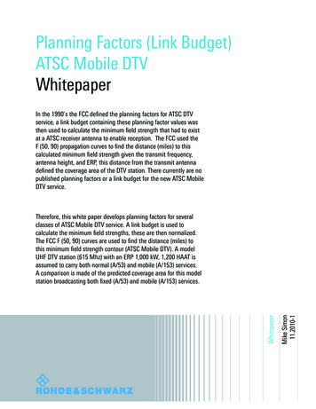
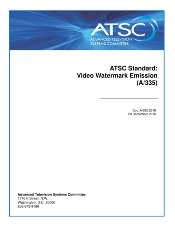
ATSC A/335:201620 September 2016Video Watermark Emission, Annex AAnnex A: Implementation of the 1X Watermark DetectorA.1OVERVIEWIn the 1X system, the luma value usable to modulate the “1” value of the symbol is specified to liewithin the range 40 to 100 (8-bit video). For optimal recovery of the watermark, the receiver shouldset the slice point halfway between the value used to modulate “0” and the value used to modulate“1”. This informative annex describes a simple algorithm a receiver can use to determine the bestslice point when the 1X system is in use.A.2DESCRIPTION OF ALGORITHMGiven that in the 1X system the receiver does not initially know the optimal slice point to use torecover the data, the following algorithm can be used to find it. The algorithm is analogous to datarecovery circuits in general use with analog communications systems: the first step in deriving theoptimal slice point for 2-level PAM encoding is to find the location of the peak in the curve offrequency of occurrence of different luma values.Figure A.2.1 illustrates an example analysis of watermark symbols. The graph was made byanalyzing watermarks that were degraded by a process of video encoding/decoding. In all, 36,966frames of video were analyzed, but similar results can be found with just a frame or two. The twolevels of encoding used were 8-bit luma values 0 and 60Luma ValueFigure A.2.1 Example count of samples with a given value of luma.On the Y-axis, the graph plots the percentage of symbols that were found to be a particularvalue of luma given in the X-axis. For example, approximately 7% of all symbols had luma value42 (the nominal, peak). Nearly zero had value 21 (exactly between the two luma values originallyencoded).13
ATSC A/335:2016Video Watermark Emission, Annex A20 September 2016A receiver can use an algorithm similar to the following to compute the peak value. Over aperiod of one or more frames:1) For each frame, derive the symbol values by averaging each set of 8 pixels in the first lineof active video and rounding to the nearest integer.2) Count the number of symbol values occuring for each luma level in the range 20 to 100.3) Determine the luma level having the highest number of observed values.The following JavaScript code implements the above algorithm. Given these variables (datastructures):rawLuma[] – A 1920-element array containing the raw luma values (8-bit values)mySymbols[] – A 240-element array containing the symbol valuesbins[] – A 256-element array containing the accumulated number of instances where a symbolvalue matched the index value of the array. Example: bins[30] holds the total number of timesa symbol value of 30 was found within some number of frames of marked video.The following function derives the symbol values given the raw luma values:function deriveSymbols() { // derive symbol values by averaging luma over 8 pixelsvar i, j, a;for (i 0; i 240; i ) { // save average luma per symbola 0;for (j 0; j 8; j ) {a rawLuma[(i*8) j];}mySymbols[i] a/8;// average luma of 8 sample}}The following JavaScript code could be used to derive the peak value of symbol luma over arange in which the upper encoded value may appear. For each frame, after the symbols arecollected in mySymbols, the accumulation into bins can be done:for (j 0; j 240; j ) {// for each symboln Math.round(mySymbols[j]);bins[n] ;}Then, after one or more frames have been processed (bin data collected), the peak can bedetermined:// find max value in range 21 to 100m 0;peak 0;for (j 20; j 100; j ) {if (bins[j] m) {m bins[j];peak j;}}14
ATSC A/335:2016Video Watermark Emission, Annex A20 September 2016For a 2-level encoding where the luma value used to encode “0” is known to be Z, the propersplice point would be (Z peak)/2.Testing has shown that even if only one frame is processed this way, a good first-approximationis given. Processing several frames can refine the value further.— End of Document —15
ATSC A/335:2016 20 SeptemberVideo Watermark Emission 2016 iv Index of Figures and Tables Figure 4.1 Marked video frame example. 8 Figure 4.2 Luma encoding - 2X System with 8-bit video. 9 Figure 4.3 Luma encoding - 1X System with 8-bit video. 10 Figure A.2.1 Example count of samples with a given value of luma. 13 Table 5.1 Horizontal Pixels per Symbol 11 .