Transcription
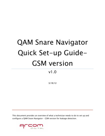
ManualDT-ATSC-QAM-8V2User Manual8 input ATSC-8VSB / QAM-B to QAM-BTrans-Modulator
DT-ATSC-QAM-8V2 ManualTable of ContentsSafety Precautions . 3Package Contents. 3Unpacking and Inspection . 4Installation . 4Introduction to DT-ATSC-QAM-8V2: ATSC-8VSB / QAM-B to QAM-B Trans-Modulator . 4Features. 4System Parsing / Response Time. 4Specifications . 5Hardware Installation . 6Device Programming and Setup . 6Connecting to the GUI Interface . 6Factory Default IP: 192.168.1.9 . 6System Setup via GUI Interface . 6Name: admin / Password: Admin123 . 6Overview Page . 7-9Ingest Setup . 10Streaming Setup . 11Streaming System Parameters . 12Customize the Streaming Setup View . 13RF Output Setup . 14Network Setup . 15Device IP Address Setup . 15Forgot IP Address . 16System Setup . 16Description . 16Time / NTP Server Setup . 17Administration . 17Reboot . 17Reset to Default . 17Backup. 18Restore . 18Firmware Update . 19Change Password .19-20Private Address Ranges, IPv4 . 20Warranty.21-222
DT-ATSC-QAM-8V2 ManualSafety PrecautionsThe presence of this symbol is to alert the installer and user to the presence of uninsulateddangerous voltages within the product’s enclosure that may be of sufficient magnitude toproduce a risk of electric shock.TO REDUCE THE RISK OF FIRE OR ELECTRIC SHOCK, DO NOT EXPOSE THIS DEVICETO RAIN OR MOISTURE. DO NOT OPEN THE UNIT. REFER SERVICING TO QUALIFIEDPERSONNEL ONLY. DO NOT apply power to the unit until all connections have been made, all components havebeen installed and all wiring has been properly terminated.DO NOT terminate, change or uninstall any wiring without first disconnecting the unit’spower adapter from the device.This device is supplied with the appropriately rated power supply. The use of any otherpower supply could cause damage and invalidate the manufacturer’s warranty.DO NOT connect the power cord to the device if the power cord is damaged.DO NOT cut the power cord.DO NOT plug the power cord into an AC outlet until all cables and connections to the devicehave been properly connected.The device should be installed in an environment consistent with its operating temperaturespecifications. Placement next to heating devices and ducts is to be avoided as doing somay cause damage. The device should not be placed in areas of high humidity.DO NOT cover any of the device’s ventilation openings.DO NOT cover or obstruct the device’s fan or fan openings.If the device has been in a cold environment allow it to warm to room temperature for atleast 2 hours before connecting to an AC outlet.Package Contents One DT-ATSC-QAM-8V2 One Power Cable One Installation / Configuration Manual3
DT-ATSC-QAM-8V2 ManualUnpacking and InspectionEach unit is shipped from the factory tested. Ensure all items are removed from the containerprior to discarding any packing material.Thoroughly inspect the unit for shipping damage with particular attention to connectors andcontrols. If there is any sign of damage to the unit or damaged or loose connectors contact yourdistributor right away.InstallationSystem Installer must adhere to Article 820-40 of the NEC that provides guidelines for propergrounding and specifies that the cable ground shall be connected to the grounding system ofthe building, as close to the point of cable entry as possible.Introduction to DT-ATSC-QAM-8V2: ATSC-8VSB / QAM-B to QAM-B Trans-ModulatorThe DataTronix DT-ATSC-QAM-8V2 is a high quality 8VSB /Clear QAM to QAM Transmodulator. It was designed to allow system integrators to receive and process up to 8 individual8VSB (ATSC) / Clear QAM channels along with up to 56 sub channels, and easily convert thesesignals to produce a high-quality RF QAM distribution system. The DT-ATSC-QAM-8V2 is ahighly flexible system allowing integrators to quickly receive, convert, and distribute high qualityDigital QAM channels to their customers.Features Accepts 8 RF inputs (ATSC-8VSB/QAM) Allows for Up to 64 Output Programs Allows User to “Cherry Pick” Desired Programs as Needed Supports STD/HRC/IRC Formats Supports Full Range of ATSC-8VSB/QAM Signals Offers 8 Fully Independent RF QAM Outputs Easy to Setup and Monitor with GUI Front Panel LED Indicators 3 VCN Modes Supported High Density 1RU DesignSystem Parsing / Response Time:The initial System Parsing time will range from 4-6 minutes on average as the system identifiesand populates the required parameters. As the user navigates the device's menu note that asmall delay may occur in populating the data on the screen as the system is constantlyperforming system parsing and system house-keeping functions.4
DT-ATSC-QAM-8V2 ManualInputWeb ManagementRF Mode (ATSC-8VSB and QAM)GigEConnector1 x F-Type, FemaleConnectorInput Impedance75 ohmModulationATSC-8VSBITU J.83 Annex B(64-QAM,256-QAM)Tuning Block Freq.Range55 to 861MHz (Center)Bandwidth6 MHzNumbers of Tuner8Input Level6 MHzLoop ThroughConnector1 x F-Type, Female, Passive1 x RJ45100 / 1000Base-T Ethernet,Full / Half cy Alert System (EAS) (Optional)GigEConnector1 x RJ45UDP / RTP100 / 1000Base-T Ethernet,Full / Half Duplex, AutoNegotiationSupported (user-selectable)ProtocolSCTE-18 SupportedStandardAlarms / MonitoringLocal MonitoringOutputQAMConnector1x “F” FemaleModulation256-QAM / 64-QAMStandardJ.83 Annex BFrequency Range57 to 861 MHz (UnderSTD Mode)8Independent RFFrequenciesChannels’ Bandwidth6 MHzOutput Level45 dBmV TypicalOutput Impedance75 ohmLevel Adjustment0 to -20 dBVCNAuto (Major & Minor)Manual (Major & Minor)Local Control8 x NIM Status LEDs /1 x Power LEDIP Reset ButtonGUI SupportedFirefox, ChromePassword ProtectedGUI: ChangeablePowerPower Supply12VDC 5.4Amp.Consumption23 W TypicalInput Voltage Range100 to 240 VACMechanical and EnvironmentalChassis (W x D x H)19.01 x 9.45 x 1.74"(483 x 240 x 44.2 mm)Weight7.9 lbs.Manual (One Part)Operating Temperature32 to 122 F (0 to 50 C)Carrier Suppression55 dBRF Output Return Loss10 dB Typical32 to 140 F (0 to 60 C)Signal-to-Noise Ratio(SNR)42 dB TypicalStorage y1-Year Limited WarrantyMER41 dB Minimum, 44 dB Typical**Specifications Subject to Change Without Notice.**5
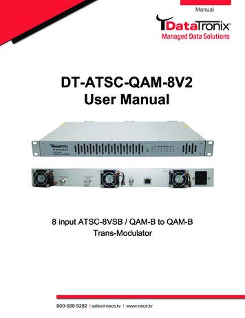
DT-ATSC-QAM-8V2 ManualHardware Installation1. Use properly installed terrestrial antennas. Verify for proper signal reception and signallevels.2. Properly connect required outputs of terrestrial antennas/splitter feedsto the DT-ATSC-QAM-8V2.3. Apply Power to the DT-ATSC-QAM-8V2.4. Connect an Ethernet cable from Utility Port on the DT-ATSC-QAM-8V2 to a PC/MAC.Device Programming and SetupConnecting to the GUI Interface1. Connect an Ethernet Cable directly to the Utility Port on the rear panel of the device orconnect the Ethernet cable to an Ethernet switch. Connect an Ethernet cable to YourPC/Laptop2. Modify Your PC/Laptop IPV4 address to 192.168.1.113. Enter Default IP Address for DT-ATSC-QAM-8V2 into Your Web Browser(Suggested browser: Firefox or Chrome)Factory Default IP: 192.168.1.9System Setup via GUI InterfaceAfter connecting the device to the GUI interface (please see descriptions above):1. Enter device's IP address in web browser.2. Login: Enter unit Name/PasswordName: admin / Password: Admin123Note: To modify the systempassword, go to the[Administration Page] of thedevice.6
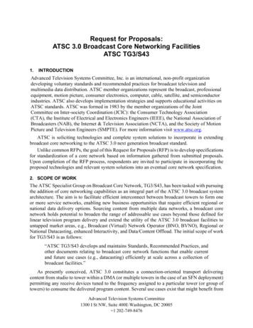
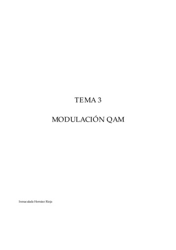
DT-ATSC-QAM-8V2 ManualOverview Page[Overview Page] provides an overall system status of the DT-ATSC-QAM-8V2 including:RF Input Type, Frequency, SNR, Signal Status, and Programs**.**Programs : If you move your cursor to “below as example) of the Programs.” you will see the detailed information (see figure7
DT-ATSC-QAM-8V2 ManualOverview (RF Output): RF Outputs showing the number of sub-streams/programs8
DT-ATSC-QAM-8V2 ManualOverview (Fan): This tab shows fan status and system uptime9
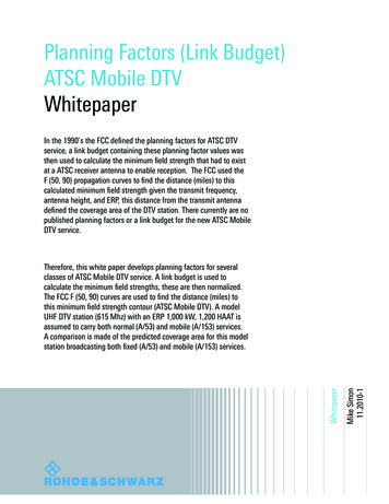
DT-ATSC-QAM-8V2 ManualIngest SetupUse the [Ingest Setup] page to configure each input. Up to 8 individual - ATSC or QAM inputscan be assigned.Ingest Setup Procedures1. Select Ingest setup tab from the top menu2. Select the appropriate ingest input (1 thru 8). Enable as required3. Select Standard: ATSC or QAMATSC: 8VSB / QAM: STD / QAM: HRC / QAM: IRC4. Select Constellation: For QAM select 64-QAM or 256-QAM as required5. Select Frequency (MHz) (Input)ATSC-8VSB: UHF (CH 14 – 69) VHF (CH 2-13)QAM: CH 2 – CH 135 (57 MHz to 861 MHz)6. Save and Confirm to save all changes*****Note: Leaving any ingest setup page without saving the set parameters will causethe device to revert to the last saved settings.10
DT-ATSC-QAM-8V2 ManualStreaming SetupUse the [Streaming Setup] page to set the output: SID, Select VCN Mode Type, VCN, ShortName, and other parameters.Enable / Select / and Setup Streams1. Enable each stream/program as required by checking the check boxNote: To remove a stream/program - deselect/uncheck the stream(s) #on the left side of the table2. Modify SID (Services Output ID)Note 1: If installing multiple DT-ATSC-QAM-8V2 units make sure not to duplicate SIDoutputsNote 2: Enter SID for a program and the followed programs will be assigned by consecutivenumbers3. Enter Short Name [1-7 Characters]4. Enter Long Name [1-16 Characters]5. Select VCN Mode:VCN Mode 2-Part Auto [Example 102.1 – Set Automatically by the Device]VCN Mode 2-Part Manual [102.2 – Manual Entry by User]VCN Mode 1-Part Manual [102 – Manual Entry by User]Note: Only 1 VCN mode type can be selected6.7.8.Modify Source ID as requiredNote: If installing multiple DT-ATSC-QAM-8V2 units make sure not to duplicate source IDoutputsSelect RF# from 1-8 to assign programs to desired carrierNote 1: Bitrate mapping may be required based on the Mbps of the streams/programs inthe RF OutNote 2: Use the streaming setup page to move program(s) as needed to allow forincreased overhead of required programsSave and Confirm all parameters*****Note: Leaving any Streaming Setup page without saving the set parameterswill cause the device to revert to the last saved settings11
DT-ATSC-QAM-8V2 ManualStreaming System ParametersInputInput No.Total Input Number Received by TunerPMT PIDProgram Map Table PIDVideo PIDVideo Stream PIDAudio PIDVideo Stream PIDTS IDInput Transport Stream IDSIDService ID (Program ID)Short NameFrom Content ProviderLong NameFrom Content ProviderBit RateInput Bit RateOutputSIDService ID - DefinablePMT PIDProgram Map Table PIDVideo PIDVideo Stream PIDAudio PIDAudio Stream PIDShort NameDefinable [1-7 Characters]Long NameDefinable [1-16 Characters]VCN ModeSelectable (Auto 2-Part, Manual 2-Part,Manual 1-Part.)VCNDefinable (When Using Manual VCN Modes)Source ID#Definable12
DT-ATSC-QAM-8V2 ManualCustomize the Streaming Setup ViewThe [Streaming Setup] parameters page is easily customizable for each system.To customize the parameters shown:1.Select “Select Columns” tool2.Add or remove parameter as needed by selecting or deselection3.Close window after selecting / deselecting parameters13
DT-ATSC-QAM-8V2 ManualRF Output SetupUse the [RF Setup Page] to properly setup each RF output channel.Enable / Disable RF output as required.Enter TS ID (Transport Stream ID) value.Enter regional name as requiredSelect RF type [Normal, Inverted, C.W.]Select Channel type [STD, HRC, IRC]Set CH/Freq. [CH 2 – CH 135 / Freq. 57MHz 861MHz]Note: DT-ATSC-QAM-8V2 is frequency agile7. BW: factory set [6MHz]8. Set attenuation [ 0 -20dB. 1dB Steps]9. Select constellation [64-QAM , 256-QAM]10. Select interleaver – change as required.[Default: I 128, J 1]11. Save and Confirm all changes1.2.3.4.5.6.Note 1: Bitrate Mbps shown allows the integrator to quickly review assigned streambitrate allocated and CapacityNote 2: Bitrate mapping may be required based on the Mbps of the streams/programsin the RF OutNote 3: Use the [Streaming Setup Page] to move program(s) as needed to allow for increasedoverhead of required programsNote 4: Leaving any [RF Output Setup Page] without saving the set parameters will causethe device to revert to the last saved settings14
DT-ATSC-QAM-8V2 ManualNetwork SetupDevice IP Address Setup1.Select network setup tab to manage the IP address of the device2.Modify hostname as required3.Select DHCP or static IP4.For Static IP: select static IP and enter static IP address for device5.Enter Subnet Mask6.Enter Default Gateway7.Enter DNS Server 1 address8.Enter DNS Server 2 address (if required)9.Save and Confirm all changes15
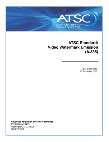
DT-ATSC-QAM-8V2 ManualForgot IP AddressYou can return to the default IP address (factory default) setting from via front panel by followingthe steps below:1. Press the Reset button from the front panel (Circled in Picture Below)Reset Button2. Power on the unit3. Release the reset button once the power LED stops flashing and become static green4. Unit’s IP address will revert back to default IP: 192.168.1.95. Unit’s login data will revert back to factory defaultName: admin / Password: Admin123Note: ONLY THE IP ADDRESS WILL REVERT BACK TO DEFAULT SETTING,- NOCHANGES WILL BE MADE TO THE CONFIGURATIONSystem SetupDescriptionUse the [System Setup Page] to designate location and descriptionof the DT-ATSC-QAM-8V2 unit.16
DT-ATSC-QAM-8V2 ManualTime / NTP Server SetupUse the time tab to set the units system time and time zone and NTP Server.1.2.3.4.5.Select time tab on system setup pageSelect time zone from the drop-down toolEnter NTP Server 1 / 2 addresses as requiredSelect synchronize system with PC clock as requiredSelect apply to apply all changesAdministrationRebootUse the Reboot button to reboot the device. No parameters will be changed.Reset to DefaultUse the Reset to Default button to reset all parameters to original factory settings.17
DT-ATSC-QAM-8V2 ManualBackupWe highly recommend saving your device’s setting.1. Select administration tab2. Select backup from the menu3. User can choose which data required backup from the following pages: Ingest setup /Streaming Setup / RF Out Setup / Network Setup / System Setup4. Locate and Name file for future useNote: The backup can be imported to assist in setting up new or multiple devices onsite.Remember to Save and backup any and all changes.Restore1. Select administration tab2. Browse the required file to be imported3. Select “Upload” to import the selected file into the device******Note: Do not power off the unit while importing.18
DT-ATSC-QAM-8V2 ManualFirmware UpdateUse the Firmware Upgrade section to import new FW version.1.2.3.4.Select administration tabSelect firmware upgrade tabBrowse to locate the required image file to be uploadedSelect “Upload” to import the selected file into the device*******Note: Do not power off the unit while importing.Change PasswordUse the password section to change or modify the device’s password as desired.19
DT-ATSC-QAM-8V2 Manual1.2.3.4.Select administration tabSelect password tabFollow listed instructionsSave and Confirm to apply new password.Private Address Ranges, IPv4Private IPv4 addresses are addresses set aside by the IANA (Internet Assigned NumbersAuthority) for use within networks that will not directly communicate or be seen by the internet.These private addresses cannot be used on the Internet or be used to communicate with theInternet. ISP’s filter out and delete packets using private IP addresses.Any organization that uses private IP addresses on devices that communicate with the internetmust use a device that performs Network Address Translation.Anyone can us private addresses and they are not required to seek permission to use them.Again, networks using private IP addresses cannot communicate directly with the internet.There are three blocks of addresses that are set aside by IANA for use in private internets andare not publicly routable on the global internet:Private Class A Range:10.0.0.0- 10.255.255.255Private Class B Range:172.16.0.0- 172.31.255.255Private Class C Range: 192.168.0.0- 192.168.255.255It is important to note that only some of the 172.xx.xx.xx and the 192.xx.xx.xx address rangesare designated for private use. The remaining addresses are public and can be routable via theglobal Internet.More information regarding private addresses can be found at http://www.iana.org andhttps://www.arin.net.20
DT-ATSC-QAM-8V2 ManualDATATRONIX 1-Year Limited WarrantyDATATRONIX. (the "Company") warrants to the Original Purchaser that the item purchased isfree from defects in workmanship or material under normal use. This warranty starts on the dateof shipment of the hardware to the Original Purchaser.During the warranty period, the Company agrees to repair or replace, at its sole option, withoutcharge to Original Purchaser, any defective component. To obtain service, the OriginalPurchaser must return the item to the Company properly packaged for shipping. All defectiveproducts must be returned to the Company within thirty (30) days of failure. Products must bereturned with a description of the failure and Return Merchandise Authorization (RMA) numbersupplied by the Company. To receive a RMA number and a return shipping address on where todeliver the hardware, call 610-429-1821. The shipping, and insurance charges incurred inshipping to the Company will be paid by Original Purchaser, and all risk for the hardware shallremain with the Original Purchaser until such time as Company takes receipt of the hardware.Upon receipt, the Company will promptly repair or replace the defective unit, and then returnsaid unit to Original Purchaser, shipping prepaid. The Company may use reconditioned or likenew parts or units, at its sole option, when repairing any hardware. Repaired products shallcarry the same amount of outstanding warranty as from original purchase. Any claim under thewarranty must include dated proof of purchase or invoice. In any event, the Company's liabilityfor defective hardware is limited to repairing or replacing the hardware.This warranty is contingent upon proper use of the hardware by Original Purchaser and doesnot cover: if damage is due to Acts of God (including fire, flood, earthquake, storm, hurricane orother natural disaster), accident, unusual physical, electrical, or electromechanical stress,modifications, neglect, misuse, operation with media not approved by the Company, tamperingwith or altering of the hardware, riot, war, invasion, act of foreign enemies, hostilities (regardlessof whether war is declared), civil war, rebellion, revolution, insurrection, military or usurpedpower or confiscation, terrorist activities, nationalization, government sanction, blockage,embargo, labor dispute, strike, lockout or interruption or failure of electricity, air conditioning, orhumidity control, internet, network, or telephone serviceThe warranties given herein, together with any implied warranties covering the hardware,including any warranties of merchantability or fitness for a particular purpose, are limited induration to one year from the date of shipment to the Original Purchaser. Jurisdictions vary withregard to the enforceability of warranty limitations, and you should check the laws of your localjurisdiction to find out whether the above limitation applies to you.The Company shall not be liable to your for loss of data, loss of profits, lost savings, special,incidental, consequential, indirect, or other similar damages arising from breach of warranty,breach of contract, negligence, or other legal action even if the Company or its agent has beenadvised of the possibility of such damages, or for any claim brought against your by anotherparty. Jurisdictions vary with regard to the enforceability of provisions excluding or limitingliability for incidental or consequential damages. You should check the laws of your local21
DT-ATSC-QAM-8V2 Manualjurisdiction to find out whether the above exclusion applies to you.This warranty allocates risks of product failure between Original Purchaser and the Company.The Company's hardware pricing reflects this allocation of risk and the limitations of liabilitycontained in this warranty. The warranty set forth above is in lieu of all other express warranties,whether oral or written. The agents, employees, distributors, and dealers of the Company arenot authorized to make modification to this warranty, or additional warranties binding on theCompany. Accordingly, additional statements such as dealer advertising or presentations,whether oral or written, do not constitute warranties by the Company and should not be reliedupon.This warranty gives you specific legal rights. You may also have other rights which vary fromone jurisdiction to another.Product Notes:Model Number:Serial Number:Purchase Date:Purchased from:Install Date:22
Supports STD/HRC/IRC Formats Supports Full Range of ATSC-8VSB/QAM Signals Offers 8 Fully Independent RF QAM Outputs Easy to Setup and Monitor with GUI Front Panel LED Indicators 3 VCN Modes Supported High Density 1RU Design