Transcription
PC-Mapper 5.x and CMT Survey 6.xReference GuideA Supplement to the PC-GPS Reference GuideNotice:Reproduction or use without express written consent fromCorvallis Microtechnology, Inc. of any portion of this manualis prohibited. All rights reserved.Corvallis Microtechnology, Inc. reserves the right to make changes toits products and specifications without notice.Printed in the United States of AmericaCopyright 1993 - 2003 by Corvallis Microtechnology, Inc.
End User License AgreementPC-Mapper and CMT Survey End User License AgreementThis is a legal agreement between you, the End User, and Corvallis Microtechnology, Inc.(“Company”). By opening the sealed package containing PC-Mapper or CMT Survey andinstalling it on your PC, you are agreeing to be bound by the terms of this agreement.1. The PC-Mapper and CMT Survey software contains intellectual property, i.e., softwareprograms, that are licensed for the end user customer’s use (“End User”). The licensedsoftware programs are protected by United States copyright laws and international treatyprovisions.2. A sale of the PC-Mapper or CMT Survey software is not a sale of the intellectual propertythat it contains. The End User is granted the right to use such intellectual property, but is notownership.3. The End User shall not copy, disassemble, or reverse compile the software programs.4. The software programs are provided to the end user “as is” without warranty of any kind,either express or implied, (including, but not limited to, general, special, consequential orincidental damages including damages for loss of business profits, business interruption, loss ofbusiness information and the like), arising from or in connection with the delivery, use orperformance of the software programs. Information in the PC-Mapper and CMT Survey User’sManual is subject to change without notice and does not represent a commitment on the part ofCorvallis Microtechnology.This Agreement is governed by the laws of the State of Oregon. If you have any questionsconcerning this Agreement, please write to:Customer Service, Corvallis Microtechnology, Inc., 413 SW Jefferson Avenue, Corvallis, Oregon97333, USA.Liability StatementCMT makes no expressed or implied warranty with regard to the PC-Mapper or CMT Surveysoftware or the merchantability or the fitness of the software for any particular purpose. Thesoftware is made available solely on an “as is” basis and the entire risk to its quality andperformance is with the user. Should the PC-Mapper or CMT Survey software prove defective,the user shall bear the entire cost of all necessary correction and all incidental or consequentialdamages in connection with or arising out of the furnishing or use or performance of saidsoftware. If the material portion of said software, i.e. the disk containing PC-Mapper or CMTSurvey proves to be defective, the only remedy is the replacement of the material portion byCMT.Trademark Acknowledgments: AutoCAD is a registered trademark of Autodesk. ARC/INFO, ArcView, and ESRI Shape File are registered trademarks of ESRI. Microsoft, MS, MS-DOS, Windows, Access, FoxPro, Excel, ODBC, OLE and API areregistered trademarks of Microsoft Corporation. dBASE is a registered trademark of Ashton Tate Corporation. IBM is a registered trademark of the International Business Machines Corporation. KERMIT is a file transfer protocol developed and supported by Columbia University.
TABLE OF CONTENTSSection 10 - COGO Functions110.1 Summary of COGO Functions110.2 Working with Cogo Functions310.2.110.2.210.2.310.2.410.2.5Cogo ViewCogo MouseSelecting Data for Cogo FunctionsDisplaying the SolutionStoring new Coordinates3558910.3 Cogo Configuration (View/Configure)1010.4 Traverse Function1110.5 Scale Function1410.6 Rotate Function1510.7 Translate Function1710.8 Corner Angle Function2010.9 Multiple Points Function2110.10 Direction Cut Function2310.11 Hinge Cut Area Function25Section 11 - Map Labels2911.1 Segment Label2911.2 Marker Label3611.3 Angle Label3911.4 Area Label43Section 12 - Field Work in CMT-SURVEY12.1 Field Work Setup12.1.1 Instrument Setup12.1.2 EDM Setup47484849
12.1.312.1.412.1.512.1.6Instrument Condition SetupEnvironmental CorrectionsRepetition SetupBS/FS Setup12.2 Field Work Procedure12.2.1 General Notes on Data Collection12.2.2 Field Work/Collect4951515354545412.3 Occupy Station5512.4 Record Backsight5712.5 Record Side-Shot or Traverse Point5812.6 Foresight options5912.6.1 Offset Shots12.6.2 Remote Object12.7 Using Sets to Improve Accuracy12.7.1 Repetition Angles12.7.2 Direction Sets596164646512.8 Viewing Measurement Data6612.9 Survey Adjustment6712.10 out SetupPoint StakeoutOffset StakeoutSlope StakeoutElevation Stakeout696971757912.11 Field Work Tutorial80Section 13 - Road Design8713.1 Creating or Selecting a Road File8713.2 Road Properties8813.2.113.2.213.2.313.2.413.2.5Road SetupHorizontal AlignmentVertical AlignmentCross SectionWidening8888909193
13.2.6 Super Elevations9413.3 Road/Layout9513.4 Road/Save97INDEX99
Section 10 - COGO FunctionsThis section covers some of the commonly used Cogo menu functions. If you need informationon any COGO function that is not discussed in this section, please refer to the OnLine Manual(Help/OnLine Manual). This chapter applies to PC Mapper 5.x and CMT-SURVEY 6.x only.10.1 Summary of COGO FunctionsThe coordinate geometry (Cogo menu) operations let you define new points by variousmathematical techniques. The Cogo functions are outlined briefly in the table below.Function Name &Function Name &Purpose:Purpose:Traverse(See Section 10.4)Traverse (create points) by direction anddistance, or by Scale factor. Solve to calculate coordinates of new Point Store to save coordinates of new PointCogo T/R/S - Scale(See Section 10.5)Scale a Feature to a fixed Point. Solve to move Feature Store to save Feature coordinatesCogo T/R/S - Rotate(See Section 10.6)Rotate a Feature around a fixed Point. Solve to rotate Feature Store to save Feature coordinatesCogo T/R/S - Translate(See Section 10.7)Inverse(See OnLine Manual)Determine direction and distance between Points. Solution automatically calculated Solve to store coordinates of inverse on a line2 Point Resection(See OnLine Manual)Use angle and distance data to two known Points to calculatecoordinates of a new Point. Solve to calculate coordinates Store to save coordinates3 Point Resection(See OnLine Manual)Use angle data to 3 known Points to calculate coordinates of anew Point. Solve to calculate coordinates Store to save coordinatesHorizontal Curve(See OnLine Manual)Move a Feature to new coordinates.Define and place a Horizontal Curve. Solve to move Feature Solve to generate curve and calculate defining points Store to save Feature coordinates Store to save curve and defining pointsCorner Angle(See Section 10.8)3 Point Curve(See OnLine Manual)Find the corner angle defined by 3 Points.Define a Horizontal Curve using 3 known Points. Solve to generate curve, calculate segment and sector area Store to store curve and PI, RP coordinatesSolution automatically calculatedPC-GPS Reference Guide1
(See Section 10.9)Multiple PointsCurve between TangentsDefine new Points at equal intervals betweentwo known Points. Solve to calculate coordinates Store to save coordinatesDirection CutDetermine the Curve between two Tangent lines.(See Section 10.10)Solve to calculate coordinates Store to save coordinatesHinge Cut Store to save coordinatesStation Offset Store to save coordinatesIntersection(See OnLine Manual)Create new Points based on Line intersections. Solve to calculate coordinates Store to save coordinates(See OnLine Manual) Solve to calculate Radius Point Store to store Radius Point(See OnLine Manual) Solve to calculate Vertical Curve solution Print to print the curve solution(See OnLine Manual)Spiral CurveCreate Stakeout Points from a Line or AreaFeature.Solve to calculate coordinatesStore to store curve and PI, PC, PT RP coordinatesDefine and place a Vertical Curve.(See OnLine Manual) Vertical CurveDetermine the cut Point for a specific area by ahinge Point.Solve to calculate coordinatesSolve to generate curve and defining pointsDetermine the Radius Point from a known PC, PT and radius.(See Section 10.11) Radius PointDetermine the cut Points for a specific area bydirection. (See OnLine Manual)Define and place a Spiral Curve. Store to calculate Spiral Curve solution Print to print the curve solution(See OnLine Manual)Curve by RadiusCreate curve based on known PI, direction of tangent lines and curveradius. Solve to calculate solution points Store to save coordinatesTRS Least Square Fit (See OnLine Manual)Earth Work (Version 6.x only. See OnLine Manual)“Fit” Features in one NEZ plane (Plane 1) toanother NEZ Plane (Plane 2). One or morepoints in both Planes must be in the samelocation. These points are the “Control Points”.Define area sections and compute volumes based on cross-sectionsor borrow-pit areas.2PC-GPS Reference Guide
10.2 Working with Cogo FunctionsThis sub-section covers the use of the Cogo View and the Cogo mouse. The COGO functionscan be applied to the Feature data in your Job file or Map file. The functions are useful formaking design drawings and creating stake Points that can be downloaded to the GPS datacollector for use in stakeout work.To define meaningful Point, Line and Area Features, please use the Map/Coordinate Systemfunction to verify or set the proper datum, coordinate system and units before starting COGOwork. Also, check the settings under the View/Configure menu and the Angle and COGOoption and make sure they are consistent with your units of measurement. The View/Configurepage will also be used to set units for your angle measurements (see Section 10.3). It isadvisable not to change the datum and coordinate system unnecessarily.It is also advisable to set the proper map scale before starting a COGO design job. To do so,edit or type over the data in the “1 inch:” or “1 cm:” field in the Tool Bar. The currently activeunit of length is displayed to the right of this field.When using the COGO functions to create a curve based on given Point Feature(s), pleasekeep in mind that the new curve (a Line Feature) is a separate entity from the Point Feature(s).Similarly, the Station Offset Points created on or alongside a Line Feature do not become partof the Line Feature. If you wish to treat the original and new Features as a group, such as forthe COGO Scale, Rotate and Translate operations, you could store the newly created Featureunder the same Topic name as the original Feature. You may then easily select all theFeatures under the same Topic for COGO Scale, Rotate or Translate by double-clicking theTopic name in the Topic View.The new Features created by most of the COGO functions will be stored in a horizontal plane at0 elevation. For example, when you select three Point Features to solve for a 3-Point Curve,only the (X,Y) coordinates of the three Points will be used in generating the curve andcalculating the radius point and the point of intersection of the tangents. You may change theelevation of any Feature by editing the coordinates in the Feature Properties dialog.However, a number of the COGO functions do make use of the elevation information. Forexample, the Traverse function lets you traverse in three dimensions. Also, you may translateor scale Features in three dimensions by using COGO Translate or COGO Scale, respectively.In addition, when you create a number of points at fixed intervals, the COGO Multiple Pointsfunction will store the new Points with the proper elevation values. And, of course, the COGOVertical Curve function will create Points in a vertical plane at the specified interval.10.2.1 Cogo ViewWhen you first select an option from the Cogo menu, the Cogo View will be displayed on theright-hand side of the screen. The active Cogo function will be listed at the top of the CogoView.The input and output fields displayed in the Cogo View vary according to the function selected.For example, when you select the Cogo/Traverse function, the “Cogo View” on the followingpage is displayed:PC-GPS Reference Guide3
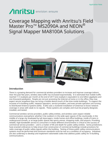
When the Cogo View is active for a function, a check mark will be displayed next to theassociated Cogo menu option:In this example, the Traverse function is selected.The Traverse option is marked with a check.You can toggle OFF the Cogo View by un-markingthe View/Cogo View menu option or clicking theToggle Cogo View icon.4PC-GPS Reference Guide
10.2.2 Cogo MouseWhen you select a function from the Cogo Menu, the Cogo Mouse is immediately made active.The Cogo Mouse icon, displayed on the tool bar, is displayed in light blue when the CogoMouse is active (or toggled ON). You can toggle the Cogo Mouse ON or OFF by clicking on theCogo Mouse icon:The Cogo Mouse is used to select Features for Cogo functions. The Cogo Mouse is also usedto indicate distance or direction for certain Cogo functions. To indicate distance, the CogoMouse activates the “Cogo Distance Circle”. To indicate direction, the Cogo Mouse activatesthe “Cogo Direction Line”. In this manual, the term Cogo Mouse Field is used to describe fieldsthat accept input based upon the Cogo Mouse. When you place your mouse in a Cogo MouseField, the field will be highlighted in red.The Cogo Mouse must be toggled ON in order for Cogo Mouse fields to accept mouse input. Ifthe Cogo Mouse field will not accept mouse input, the Cogo Mouse probably is not toggled ON.Click on the Cogo Mouse icon on the tool bar to toggle it back ON.When the Cogo Mouse is toggled ON, some of the standard PC-GPS mouse functions will notbe accessible. You may notice that you cannot access the Feature Properties screen bydouble-clicking on a Feature if the Cogo Mouse is active.Please note:Your mouse cursor will look the same regardless of whether the Cogo Mouseis toggled ON or toggled OFF. However, if the Cogo Mouse is active, yourCogo Mouse icon will be displayed in light blue. If the Cogo Mouse icon isnot active, then the Cogo Mouse icon will be displayed in gray.10.2.3 Selecting Data for Cogo FunctionsThe input fields in the Cogo View vary according to the selected Cogo function. Data can beentered in the Cogo input fields using several methods: by Cogo Mouse, by Keyboard, or byPull-Down Menu.Selecting Features using the Cogo Mouse:All the Cogo functions have input fields for specific Feature numbers or Feature names.(Example: From Point field in Traverse function.) These fields are Cogo Mouse Fields.To select a Feature for one of these fields, first click your mouse cursor in the input field(e.g. From Point field in Traverse function). The input field will be highlighted in red. Next, clickyour mouse on the Feature you wish to select. The Feature name will then be displayed in theinput field.If you would like to change the selection, you can either click on another Feature or simply typethe Feature name in the input field.Un-Selecting Features:PC-GPS Reference Guide5
Selected Target Features may be “un-selected” by clicking the right-mouse button on thehighlighted Feature in the Map View. Alternatively, you may right double-click on the Topicname in the Topic View. All of the Features in the Topic will be un-selected.Multiple Feature SelectionFor the COGO Scale, Rotate and Translate functions, you may select more than one Featureas the “Target”. This is particularly useful when you need to translate the entire Job to a correctreference point. It is also useful when you wish to move or scale a Line or Area Feature alongwith the Point Features from which it was created.When you select a Target Feature for the COGO Scale, Rotate or Translate functions, it isadded the “Target Features list”. When the Target Features field is highlighted, you may clickon another Feature to add it to the list. Or, you may add all Features in a Topic to the list bydouble-clicking the corresponding Topic name in the Topic View. To work on all Features in theJob at the same time, simply click on Edit/Select All.Please note:The Cogo Mouse must be active in order to select Features for Cogofunctions by using the mouse.An Add button is provided by the COGO Scale, Rotate and Translate functions to let you add aFeature to the Features list by entering its Feature ID into the Target Features field. To add aFeature, enter the Feature ID in the field above the Target Features list and then click on theAdd button.Selecting Angle Reference PointsAngle data for Cogo operations can be entered into the input fields using three differentmethods: by reference points, by Cogo Direction Line or by keyboard. For the referencepoint method, you select two reference points, called P1 and P2, from the Map. The azimuthbetween the P1 and P2 is the angle that will be automatically entered in the correspondingAzimuth or Angle field.The by Cogo Direction Line and by keyboard methods are described in the next two subsections.Using the Cogo Direction Line and Cogo Distance CircleMany of the Cogo distance and direction fields accept input from the Cogo Mouse. When theCogo Mouse is toggled ON, distance and azimuth can be quickly entered into these fields usingthe Cogo Direction Line and Cogo Distance Circle.The Direction Line and Distance Circle are immediately displayed on the Map View when yourcursor is placed in a Cogo Mouse direction or distance field. The direction or distance field willalso be highlighted in red. (Not all distance and direction fields accept mouse input, so if thefield is not highlighted in red, then you will need to enter the values via the keyboard.)Please note:The Cogo Mouse must be toggled ON in order for the Distance Circle orDirection Line to become active.Example using the Cogo/Traverse function6PC-GPS Reference Guide
When you select the Cogo/Traverse function, the Direction Line is used to indicate the Azimuthand the Distance Circle is used to indicate the Horizontal Distance.When you place the Cogo Mouse cursor in a direction field, like the Azimuth field shown above,the direction line will be displayed in the Map View. The value in the direction field correspondsto the current position of the direction line. When you move the direction line by dragging yourmouse cursor across the Map View, you will notice that the direction value changes accordingly.When the value is correct, click your left-mouse button to “save” that direction value.Please note:If you wish to enter a direction value using the keyboard, place your cursor inthe field, double-click to highlight the field, then type-over the current valueand immediately press the TAB key to save the new value.When you place the Cogo Mouse cursor in a distance field, like Horizontal Distance field shownabove, the distance circle will be displayed in the Map View. The value in the distance fieldcorresponds with the radius of the distance circle. When you increase or decrease the size ofthe direction circle by moving your mouse, you will notice the distance value changesaccordingly. When the value is correct, click your left-mouse button to “save” that directionvalue.Please note:If you wish to enter a distance value using the keyboard, place your cursor inthe field, double-click to highlight the field, then type-over the current valueand immediately press the TAB key to save the new value.Entering Data via the KeyboardSome of the Cogo functions have input fields which require keyboard input.(Example: Vertical Distance field in Traverse function)PC-GPS Reference Guide7
To enter values into these fields, simply place your cursor in the associated field and then enterthe appropriate number. To type over existing data, first double-click on the data field tohighlight it, then key in the new value. Note: Keyboard-only input fields, like Vertical Distance,will not be highlighted in red when you place the mouse cursor in the field.Entering Angle Data by KeyboardSome COGO data input fields are for entering angle data. If the Angle Unit is set to D.M.S. inthe View/Configure/Cogo dialog (Section 8.3), the angle data will be displayed with the degrees,minutes and seconds symbols such as in 90 15’25.2230”. To change the displayed anglevalue, first double-click the data field to highlight it, then type over the existing data in thedd-mm-ss.ssss format. For example, to enter an azimuth of 90 15’25.2230” for the Traversefunction, you would key in 90-15-25.2230. To enter a bearing of N35 15’25.2230W”, key inN35-15-25.2230W. Press the TAB key to save the data you just entered.If you just wish to change a couple digits in the displayed data, you may place the mouse cursornext to those digits, use the Delete or Backspace key to clear them, then type in the new digits .Using Cogo pull-down fieldsSome of the Cogo functions have pull-down selection fields. (Example: Mode field in theTraverse function)To enter data in the pull-down field, click the mouse on the down-arrow and then click on one ofthe options displayed. The selected option will be displayed in blue until you release the mousecursor.Moving between Cogo Input fieldsYou can use either the TAB key or mouse cursor to move between fields.Deleting Data in Cogo Input fieldsTo delete data in a Cogo Input field, place your cursor in the field, double-click to highlight thefield and then use the delete key to erase the contents of the field.10.2.4 Displaying the SolutionAfter you have entered all the required values for the Cogo Function you are using, click the“Solve” button in the Cogo View to calculate the solution.8PC-GPS Reference Guide
If the solution involves the creation of Points, then a green node will be displayed at thecoordinate location of the new Point. The example above shows the Traverse function.If the solution involves moving existing Points, the selected Points will be moved to the newlocation when you use the Solve button. (Example: Scale, Translate, and Rotate functions.)The new locations will not be saved unless you click the “Store” button.10.2.5 Storing new CoordinatesThe “Store” button is used to save the coordinates of Points created by the Cogo functions.When you click the “Store” button, the Feature Setting dialog box will be displayed:This dialog box is used to specify the Start ID number and Topic for the new Point.The default Topic name corresponds to the Cogo function which was used to create the newPoint. In the example shown above, the new Point was created by the TRAVERSE function, andtherefore the default Topic name is TRAVERSE. If you wish to rename the Topic, you can typein another Topic name in the Topic Name field.PC-GPS Reference Guide9
The Start ID number indicates the ID number or “Topic order number” for the Point. In theexample above, the Point is the first point in the TRAVERSE Topic and therefore the defaultStart ID is 1. If you want to use another ID number, you can enter another number in the StartID field. Note that the ID number must be unique.After you have verified the Start ID and Topic name for the new Point(s), click on the OK buttonin the Feature Settings dialog box. The Point(s) will be stored and displayed on the Map View.In addition, the new Topic will be appended to the Topic View.If the Cogo function has created more than one Point, the Feature Properties screen will bedisplayed immediately after you click on the Confirm button in the Feature Settings box.Each new Point created is listed in the Feature Properties dialog. The Topic name is shownunder the “Selected Shape” column. In this example, the Points were created by theCogo/Multiple Points function and the Topic name is “Multiple Points”. The first Feature IDnumber corresponds to the Start ID number listed in the Feature Settings box.When the Feature Properties dialog box is first displayed, the first Point listed will be highlightedin the Selected Shape/Type/Feature ID columns. The coordinates for the highlighted PointFeature are shown under the Latitude, Longitude and Elevation fields. To view the coordinatesof another Point, simply click on the ID number listed in the Feature ID column.To return to the Main PC-GPS screen, click on the OK button.10.3 Cogo Configuration (View/Configure)The parameters for your Cogo functions can be set using the “Angle and Cogo” page of theView/Configure menu. When you select View/Configure and click on the Angle and Cogo tab,the following dialog box is displayed:10PC-GPS Reference Guide
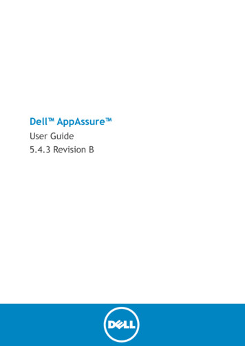
The default settings are shown in this example screen. To change any of these settings, clickon the selection circle that corresponds to one of the other options and then click on the OKbutton. For example, to change the Angle Units from D.M.S. to Degrees (decimal degrees),click on the selection circle for Degree and then click on the OK button.The options under Translate Curve/Spiral to Line by Scale are used to specify how yourCurves and Spirals will be defined in PC-GPS. In PC-GPS, Curves and Spirals are stored asLine Features. The Coarse, Medium, Fine and User selections refer to the number of nodeswhich will be used in the Line Feature. The Coarse setting corresponds to the fewestnumber of nodes needed to represent the curve, while the Fine setting corresponds to amuch larger number of nodes. For example, in a given curve, the Coarse setting mayresult in 40 nodes in the Line and the Fine setting might result in more than 1000 nodes in theLine. The User setting allows you to specify the interval between nodes. If your Map distanceunits are feet, an User interval of 1 would be equivalent to 1 node every foot along the Line.Please set the desired scale before creating Cogo Line Features.Please note:The Map distance units may be set using the Unit option under theMap/Coordinate System menu option.10.4 Traverse FunctionWhen you select the Cogo/Traverse function, a Cogo View similar to the example shown belowis displayed:PC-GPS Reference Guide11
Example of Traverse function using Angle mode(Topic View & Sheet View are OFF and Points have been labeled using Topic/Autolabel.)SummaryThe Traverse function is used to create a new Point based on direction and distancefrom a known point. Solve to calculate coordinates of new Point. Store to save coordinates of new Point. Reset to clear data fields.Options: Under the “Mode” field there are three options: Angle, Scale Factor, and HorizontalAngle. It is a good idea to first select the mode you want to use before specifyingvalues for the Cogo Input fields.Angle mode is used to create a Point based on azimuth and distance from a Point.The Point is identified as the “From Point”. The azimuth between two referencepoints (“P1” and “P2”) is used for the azimuth of the traverse. The user needs toidentify the From Point, P1, P2 and horizontal distance. (Note: If you do not want touse reference points to select azimuth, you may skip the P1, P2 fields. Instead, placeyour cursor in the Azimuth field and type-in the azimuth.)Scale Factor mode is used to create a Point based on a scale factor between the“From Point” and to “To Point”. The user needs to specify the From Point, To Point,12PC-GPS Reference Guide
and Scale Factor. Scale with elevation selection is optional. The new Point will becreated between the “From Point” and to “To Point” with the distance based upon thescale factor. For example, if the scale factor input is .5, then the new Point will beplaced half way between the From Point and the To Point. Note: If you do not usethe “scale with elevation” option, the solution point will maintain the elevation of theFrom Point.Horizontal Angle is used to create a Point based on a distance and a horizontalangle. The horizontal angle is the angle formed by the line between the From Pointand a Back Point AND the line between the From Point and the new traverse point.The user needs to specify From Point, Back Point, Horizontal Distance, andHorizontal Angle. Vertical Distance is optional.CogoFrom Point: Click Cogo Mouse on the Point Feature which is your From PointMouseP1 and P2: Click Cogo Mouse on the azimuth reference points.FieldsHorizontal Distance or Scale: Use Cogo Distance Circle to specify distance or scale.To Point or Back Point: Click Cogo Mouse on the Point Feature to be To Point orBack Point.Horizontal Angle: Use Cogo Direction Line to indicate angle.Please note:For any of the Cogo Mouse fields, you may also enter the appropriate value bykeyboard. After you enter the value, press the TAB key to move to the next field.Steps for Traverse function using the Angle mode:1. Select “Angle” in the Mode field.2. Click your Cogo Mouse on the Point Feature which is your From Point.3. Click the Cogo Mouse on the Point Feature which is the P1 reference point.4. Click the Cogo Mouse on the Point Feature which is the P2 reference point. Remember thatthe azimuth between “P1” & “P2” will be used as the traverse azimuth from the “From Point”.5. Use the Distance Circle to select Horizontal Distance. Click the mouse to save the value.6. (Optional) Enter a value for Vertical Distance.7. Click on the Solve button. A green node will be placed at the solution location.8. Click on the Store button to save a new Point at the solution location.9. Verify the Start ID and the Topic name in the Feature Settings dialog and click on Confirm.Results:A new Point will be placed at the solution location. This new Point will be assignedto the TRAVERSE topic.PC-GPS Reference Guide13
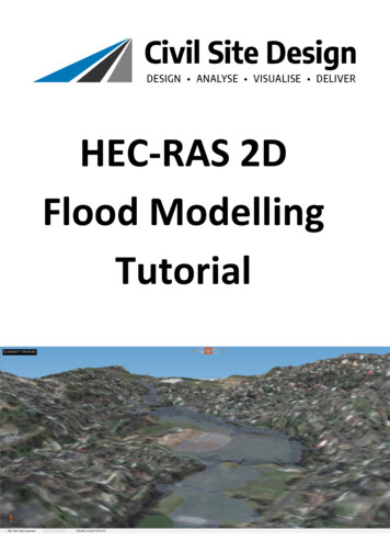
10.5 Scale FunctionWhen you use the Cogo/Translate/Rotate/Scale option, the Cogo View is displayed as follows.Note that separate input fields are provided for Translate, Rotate and Scale.Example of Scale function(Topic View & Sheet View are OFF and Points have been labeled using Topic/Autolabel.)SummaryThe Scale function is used to move a Feature based on scale distance from a fixed Point. Solve to move selected Feature. Store to save the new coordinates of the Feature. Reset to clear the data fiel
The PC-Mapper and CMT Survey software contains intellectual property, i.e., software programs, that are licensed for the end user customer's use ("End User"). The licensed . 12.6 Foresight options 59 12.6.1 Offset Shots 59 12.6.2 Remote Object 61 12.7 Using Sets to Improve Accuracy 64 12.7.1 Repetition Angles 64