Transcription
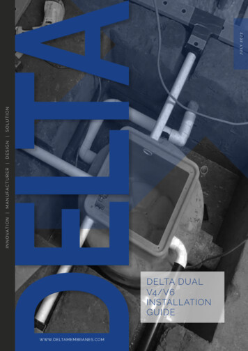
DELTA DUALV4/V6INSTALLATIONGUIDEW W W.D E LTA M E M BRA N ES . CO M1I N N O VAT I O N M A N U FA C T U R E R D E S I G N S O LU T I O NJ U LY 2 0 2 2
Commissioning DetailsProperty AddressCommissioning EngineersCustomer contact detailsContact nameContact Tel. No.Equipment InstalledApproved InstallerDate of commissioningCommissioning engineerStatusWarranty periodConditionsFully commissioned in accordance with the manufacturers instructions12 months from commissioningEquipment must be on a current service agreement with approvedservice organisationSignature of engineerSERVICING PLANSSump pumps must be maintained. We recommend a qualified engineer examinesand services equipment every year. Pumps running frequently due to higher watertable, water drainage, or weather conditions should be examined more frequently,we recommend every 6 months. Sump pumps, being mechanical devices, mayfail if not maintained which could lead to a flooded basement and costly repairs.Regular servicing of sump pumps will increase efficiency and extend the life of thepump. All Delta Membrane pump systems can be maintained and serviced by ourrecommended service companies or installing contractor.COMMISSIONINGAll sump pumps require commissioning. Commissioning provides peace of mind,knowing that the system is installed correctly and in compliance with warrantyconditions. All Delta Membrane pump systems can be commissioned by ourrecommended service companies or installing contractor.DUAL V4/V6 INSTALLATION GUIDETHIS MANUAL SHOULDBE KEPT WITH THEPUMP STATION OR THEHOMEOWNER
Contents12V4/V6 Overview1.0OVERVIEW1.1TECHNICAL INFORMATION1.2CHAMBER OVERVIEW1.3PARTS INCLUDED1.4OPTIONAL EXTRASDischarge Pipework & Fittings2.0DISCHARGE PIPEWORK & FITTINGS2.1SPARE PARTS3Pump Chamber Depth Limits4Installation Guidelines5673.0PUMP CHAMBER DEPTH LIMITS4.0INSTALLATION GUIDELINES4.1PUMP STATION LOCATIONS4.2RC BOX DIMENSIONSInstallation Of Chamber5.0INSTALLATION OF CHAMBER - SECTION A5.1INSTALLATION OF CHAMBER - SECTION B5.2INSTALLATION OF CHAMBER - SECTION C5.3INSTALLATION OF CHAMBER - SECTION D15.4INSTALLATION OF CHAMBER - SECTION D25.5INSTALLATION OF CHAMBER - SECTION D35.6INSTALLATION OF CHAMBER - SECTION E5.7INSTALLATION OF CHAMBER - SECTION F5.8INSTALLATION OF CHAMBER - SECTION GWiring Diagram6.0WIRING DIAGRAM6.1WIRING DIAGRAMMaintenance7.0MAINTENANCE7.1HEALTH & UBLESHOOTING01992 523 523 info@deltamembranes.com www.deltamembranes.com1
1. Dual V4/V6 Overview1.0 DUAL V4/V6 OVERVIEWThe Delta Dual V4/V6 is a packaged pump stationdesigned to collect ground water via perimeter channel ,modular drainage and/or clear opening to the top of thechamber - please visit our website for water collectiondetails. Typically, the Dual V4/V6 would be used to collectground water from a basement up to 150m² and/orsurface water from a light well up to 12m² to a maximumhead of 7m and 9m respectively.powerful V4/V6 pumps. It is designed to be installedby contractors with competent building, plumbing andelectrical skills. The pumps operate by fixed arm floats, theduty pump is set at a standard height (210mm to base offloat) and the backup pump is set at a high level (380mmto base of float). The high level alarm (where fitted) willoperate if the duty pump fails leaving the backup pumpto discharge water.The pump station has been specifically designed for belowground applications. The chamber is manufactured fromHDPE and when installed correctly, it is able to withstandhydrostatic forces encountered in high water tables.An AlertMaxx2 EC - High water level alarm (DMS-598)is offered as a recommended extra to alert the propertyoccupant when the water level in the chamber becomestoo high. A Hi-PowerMaxx (DMS-364-1) is recommendedto power the pumps during power outage. Please seesection 1.4 for more details about optional extras designedfor the Dual V4/V6 pump station.The pump station is delivered as a complete packageincluding, the chamber, internal pipework and two1.1 TECHNICAL INFORMATIONPump SpecificationPump TypeTypical Duty (I/S)Head 4052.753.3062.403.00P1 (kW)0.751.05P2 (kW)0.350.50Current (a)4.004.90Power PhaseSingleSingleNon Switched Fuse Spur Rating (a)1313RCBO Rating (a)1616Cable Length (m)1010Max. Temperature ( C)5050Weight (kg)7.177.40Chamber SpecificationChamber MaterialSize (mm)Volume (L)2High Density Polyethylene - ICO1314 gradeChamber Diameter660Overall Diameter902 (across spigots)Depth800Below Inlet137Total273Inspection CoverNot SuppliedClear opening to chamber (mm)310 x 310Fixed Inlets3 x 110 / 160mmCable Duct (mm)50VentN/ADischarge Connection2” / 50mm BSP Female - External to chamberInternal Pipework Manifold125” / 32mm BSP Class CDUAL V4/V6 INSTALLATION GUIDE
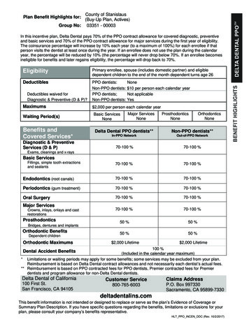
1. Dual V4/V6 OverviewDelta Dual V4/V61.2 CHAMBER OVERVIEW4.0PartChamber OverviewDescriptionAInlet PipeBPart BaseConcreteGNon-switched Fused SpurHDistribution ionA CoverInlet PipeJScreedHDPumpBChamberConcrete BaseKInsulationIECableCDuctInspection CoverLMS20J MembraneFDischarge PipeDPump ChamberMBasement SlabEFFused SpurHigh Level AlarmScreedGInsulationCable DuctLMS20 MembraneDischarge PipeMBasement SlabBIDistribution BoardKAHCDEFJKLM1.3 PARTS INCLUDED5.0Spare PartsChamber - 902 x 655mm deepPartDescription 1.25” Internal Pipework V4/V6Pump c/w 1.1 & 1.22 x1 V4/V6Pumps 7Part No.DMS-216/0841.1Float Switch AssemblyDMS-3442Discharge Arm inc. 'O' RingDMS-3263‘O’ RingDMS-13278652” Discharge Male Iron & low pressure Male Iron for temp. siteRubberNon-returnValve Iron DMS-3281.2installation.2” CableDuct Male4 1.4 OPTIONALEXTRAS1.25” Brass Gate Valve45Connector PieceDMS-32932DMS-338 AlertMaxx2ECHigh LevelAlarm (DMS-598)ConnectorAdaptorDMS-3376 2” Non-pressureIron (DMS-364-1)DMS-3357Hi-PowerMaxx2BatteryMaleBackup Y-piecec/w 2 ’O’ andringsvariousDMS-3218 Discharge1.25”Pipeworkfittings 2” Discharge Pipework and various fittings1.211.1601992 523 523 info@deltamembranes.com www.deltamembranes.com3
2. Discharge Pipework & Fittings2.0 DISCHARGE PIPEWORK & FITTINGSA selection of discharge pipework and fittings are available for the Dual V4/V6 pump station.Should you require to place an order for any of these items, please complete the form below, scan and email topumps@deltamembranes.com to allow us to process your order.Part DescriptionPart No.2” Pipe - 3m Length (Class E)DMS-01542” 90 Elbow - Plain/PlainDMS-01552” 45 Elbow - Plain/PlainDMS-01562” Socket - Plain/PlainDMS-01572” Socket - BSP Mail Thread/BSP Male ThreadDMS-3392” Male Iron - Plain/BSP Male ThreadDMS-01532” Male Iron - Plain/BSP Male Thread (Non-pressure)DMS-335110mm to 2” AdaptorDMS-341Saddle Clamp - 110mm to 2” (BSP Female Thread) including 2” Male Ironincluding 1.25” Male IronDMS-0151Saddle Clamp - 160mm to 2” (BSP Female Thread) including 2” Male Ironincluding 1.25” Male IronDMS-01522” Pipe ClipDMS-0159500ml PVC Solvent CementDMS-0158Name:Company Name:Delivery/Site Address:Email:Phone No.:Mobile No.:Sign.:Date.:Please scan this order form and email to pumps@deltamembranes.com4DUAL V4/V6 INSTALLATION GUIDEQty Req.
2. Discharge Pipework & Fittings2.1 SPARE PARTSPart DescriptionPart No.1V4/V6 Pump c/w 1.1 & 1.2DMS-216/0841.1Float Switch AssemblyDMS-3441.2Rubber Non-return ValveDMS-3282Discharge Arm inc. ‘O’ RingDMS-3263‘O’ RingDMS-13241.25” Brass Gate ValveDMS-3295Connector PieceDMS-3386Connector AdaptorDMS-33772” Non-pressure Male IronDMS-3358Y-piece c/w 2 ‘O’ ringsDMS-23401992 523 523 info@deltamembranes.com www.deltamembranes.com5
3. Pump Chamber Depth LimitsIf the inlet does not allow the pump chamber to be within depth limits, please contact DeltaTechnical on 01992 523 523 or pumps@deltamembranes.com to discuss chamber options. 500mmThe pump chamber must be installedno more than 500mm below floorfinishes. 500mmA pump chamber installed more than500mm below floor finishes cannotbe serviced safely in accordance withCDM regulations.X6DUAL V4/V6 INSTALLATION GUIDE
4. Installation Guidelines4.0 INSTALLATION GUIDELINESThe following instructions are for guidance only and it is the contractors responsibility to ensurethat the installation is in accordance with the prevailing ground conditions and good buildingpractice, to eliminate any potential damage to the pump station either during or after installation.Please read these instructions carefully prior to installing the chamber. If there is anything that isunclear, please contact our technical help desk on 01992 523 5234.1 PUMP STATION LOCATIONThis station requires routine maintenance, therefore it is important that careful consideration istaken to position the chamber in a location that allows permanent access to the chamber.4.2 RC BOX DIMENSIONS01992 523 523 info@deltamembranes.com www.deltamembranes.com7
5. Installation of Chamber5.0 INSTALLATION OF CHAMBER - SECTION AConstruction of reinforced concrete box1Excavate hole for chamber. Refer to section4.2 for RC box internal dimensions.3Lay inlet and discharge pipework. Allowpipework to protrude into RC box by aminimum of 100mm.8DUAL V4/V6 INSTALLATION GUIDE2Install re-bar as per structural engineer’sdrawings.4Pour concrete to form RC box as perstructural engineer’s drawings.
5. Installation of Chamber5.1 INSTALLATION OF CHAMBER - SECTION B1Connecting 110mm inlet pipework56Saw off socket end/s, where inlet pipe/s areto be connected.7Fit push fit coupler.Position chamber in RC box.8Connect inlet pipework to the requiredchamber spigot.01992 523 523 info@deltamembranes.com www.deltamembranes.com9
5. Installation of Chamber5.2 INSTALLATION OF CHAMBER - SECTION B2CHANNEL TO CHAMBERConnecting perimeter channel to chamberTo be followed when installing perimeter channel directly into upper side of chamber.9Mark perimeter channel position on side ofchamber.11Cut around the marked line outlining theperimeter channel using a jigsaw.10DUAL V4/V6 INSTALLATION GUIDE10Drill holes in the corners inside the areamarked in red.12Insert the perimeter channel into thechamber allowing 35mm of overhang insidethe chamber.
5. Installation of Chamber5.3 INSTALLATION OF CHAMBER - SECTION B3Connecting perimeter channel via a 1.5”/40mm inlet pipe1314Mark position of the 40mm pipe on the sideof the chamber and cut out the marked lineusing a 1.5”/40mmCut 40mm pipe to length allowing anoverhang of 35mm inside the chamber.01992 523 523 info@deltamembranes.com www.deltamembranes.com11
Installation of Chamber5.4 INSTALLATION OF CHAMBER - SECTION CCHANNEL TO CHAMBERConnecting discharge and cable duct15Wrap the thread on a DMS-0153 high pressuremale iron with PTFE tape.17Apply DMS-0158 solvent cement aroundthe first 20mm of the external face of thedischarge and cable duct pipe and internalside of their respective male iron.12DUAL V4/V6 INSTALLATION GUIDE16Screw the high pressure male iron into thefemale iron.18Push discharge and cable duct pipe into theirrespective male iron, twisting the pipe as itis pushed into the male iron to remove anytrapped air.
Installation of Chamber5.4 INSTALLATION OF CHAMBER - SECTION CCHANNEL TO CHAMBERConnecting discharge and cable duct19Ensure a draw cord is pulled through thecable duct as the cable duct is built.01992 523 523 info@deltamembranes.com www.deltamembranes.com13
5. Installation of Chamber5.5 INSTALLATION OF CHAMBER - SECTION D1Backfill around chamber with concreteTo be followed when installing chamber in an RC box.20Check all pipes are connected to thechamber correctly.22Fill void between RC box and chamberwith concrete (min. C35 grade) or as perengineer’s drawings.14DUAL V4/V6 INSTALLATION GUIDE21Completely fill chamber with water.
5. Installation of Chamber5.6 INSTALLATION OF CHAMBER - SECTION D2Backfill around chamber with concreteTo be followed when installing chamber in the ground.2324Completely fill chamber with water.Fill void between soil and chamber withconcrete (min. C35 grade) or as perengineer’s drawings.25Allow concrete to cure.01992 523 523 info@deltamembranes.com www.deltamembranes.com15
5. Installation of Chamber5.7 INSTALLATION OF CHAMBER - SECTION D3REINFORCED CAGE)Backfill around chamber with concreteTo be followed when installing chamber in the ground with a reinforced cage.26Completely fill chamber with water.28Allow concrete to cure.16DUAL V4/V6 INSTALLATION GUIDE27Fill void between soil and chamber withconcrete (min. C35 grade) or as perengineer’s drawings.
5. Installation of Chamber5.8 INSTALLATION OF CHAMBER - SECTION EInstalling pumps in chamber and AlertMaxx2 EC or Delta HLA2930Pump out water from chamber.31Manually remove any debris from chamberand residual water using a wet vacuum.32Remove discharge arms from ‘Y’ piecemanifold and screw ‘Y’ piece on to gatevalve. Ensure gate valve is fully open.Wrap PTFE tape around thread located onmale irons at the bottom of the dischargearms and screw discharge arms on topumps.01992 523 523 info@deltamembranes.com www.deltamembranes.com17
5. Installation of Chamber5.8 INSTALLATION OF CHAMBER - SECTION EInstalling pumps in chamber and AlertMaxx2 EC33Fill chamber half full with water35When installing an AlertMaxx2 EC high levelalarm, refer to the AlertMaxx2 EC installationinstructions.18DUAL V4/V6 INSTALLATION GUIDE34Lower pumps in to chamber. Ensure ‘O’ ringsare correctly seated in unions and screwdischarge arms to ‘Y’ piece manifold.36Pull pump and AlertMaxx2 EC cablesthrough cable duct.
5. Installation of Chamber5.8 INSTALLATION OF CHAMBER - SECTION EInstalling pumps in chamber and AlertMaxx2 EC3738Isolate main supply and connect each pumpto a separate non-switched fused spur.When installing an AlertMaxx2 EC, follow thewiring diagram on page 20.39Turn mains supply on and lift each pumpsfloat arm to test water is dischargingcorrectly.40To test float switch, refer to the AlertMaxx2EC installation instructions.Re-fit temporary site cover to protect thepump station.01992 523 523 info@deltamembranes.com www.deltamembranes.com19
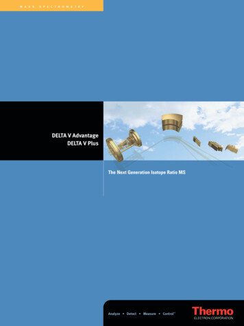
12.0Wiring Diagram (inc. AlertMaxx2)6. Wiring DiagramDual Ground Water Pump Station with AlertMaxx26.0 WIRING DIAGRAMSeparate 16 Amp RCBO’sAlertMaxx2 EC High Level Alarm(DMS-598)For internal wiring of the highlevel alarm, please refer to theAlertMaxx2 EC instruction manual.13 Amp Non-switchedfused spursFinger Float SwitchSupplied with a 10m cable- The pump is supplied with a 10m cable.- When only using the standard 10mcable attached to the pump, the cableduct should be no longer than 6m.- If the cable duct requires to be longerthan 6m, please follow the cableextension guide to select an appropriatecable core diameter.The electrical installation must comply with the requirements ofBS 7671:2018 ‘Requirements forElectrical Installations’ incorporating amendment 3:201520DUAL V4/V6 INSTALLATION GUIDE
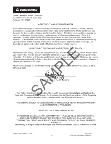
Delta Dual V4/V612.0Wiring Diagram (inc. AlertMaxx2 & Hi-PowerMaxx)6. Wiring Diagram6.1 WIRING DIAGRAMSeparate 16 Amp RCBO’sHi-PowerMaxx2 Battery Backup(DMS-364-1)For internal wiring of the batterybackup, please refer to theHi-PowerMaxx2 instruction manual.AlertMaxx2 EC High Level Alarm(DMS-598)For internal wiring of the highlevel alarm, please refer to theAlertMaxx2 EC instruction manual.13 Amp Non-switchedfused spursMaxxConnect CableFinger Float SwitchPrimaryFrom MainsSecondaryFrom MainsPrimary To Pump/AMX2 EC Mains InSecondary To Pump/AMX2 EC Mains In- The pump is supplied with a 10m cable.- When only using the standard 10mcable attached to the pump, the cableduct should be no longer than 6m.- If the cable duct requires to be longerthan 6m, please follow the cableextension guide to select an appropriatecable core diameter.The electrical installation must comply with the requirements ofBS 7671:2018 ‘Requirements forElectrical Installations’ incorporating amendment 3:20152301992 523 523 info@deltamembranes.com www.deltamembranes.com21
7. Maintenance7.0 MAINTENANCESump pumps must be maintained. We recommend a qualified engineer examines and services equipment every year.Pumps running frequently due to higher water table, water drainage, or weather conditions should be examined morefrequently, we recommend every 6 months. Sump pumps, being mechanical devices, may fail if not maintained whichcould lead to a flooded basement and costly repairs.Regular servicing of sump pumps will increase efficiency and extend the life of the pump. All Delta Membrane pumpsystems can be maintained by our recommended pump service providers or installing contractor.7.1 HEALTH & SAFETYIn order to minimise the risk of ill health or accidents when installing and/or servicing pump chambers, workers mustbe fully trained, competent and follow the health and safety guidelines below: Do not work without a risk assessment being in place. Work in accordance with the control measures identified in the risk assessment. All personnel must be vaccinated against diseases to which they may be exposed to, i.e. Tetanus, Polio, Hepatitis A&B, etc. At the time of writing, due to there being no vaccine against leptospirosis/weil’s disease, where rats may be present,ensure appropriate personal protective equipment (skin protection) is worn and ensure any cuts or abrasions are fullycovered. There should be no eating or drinking during works and only afterwards following a change of clothing and washing. Ensure electrical power to the pump is turned off/isolated before carrying out installation or maintenance. A suitable first aid kit must be close to hand.8. Guarantee8.0 GUARANTEEThe Delta Dual V4/V6 pump chamber is offered with an 18-month component guarantee from the date of commissioning.Pump chambers that have not been commissioned by a suitable qualified engineer are offered with an 18-month componentguarantee from the date of delivery.This guarantee does not cover defects caused by incorrect installation, installation/installer error, abnormal workingconditions, misuse, or neglect.Any defects or malfunctions should be reported to Delta Membrane Systems Limited immediately to avoid anysubsequential damage to other components of the system. All broken components should be returned to Delta MembraneSystems Limited at customer cost.To make a Pump or Pumping Accessory Warranty Claim, please email pumps@deltamembranes.com. Forms are availablefor download from our website www.deltamembranes.com.In no event shall we be liable for any consequential damage, penalties, loss, or expenses howsoever arising, out of or inconnection with incorrect installations, including, without limitation, direct or indirect loss, consequential loss or damage,loss of profit or goodwill, loss arising from any errors or omissions in the pump chamber as a result of, incorrect installation,installation/installer error, abnormal working conditions, misuse, or neglect.We shall not accept liability if the pumping system fails due to being incorrectly specified by any third parties not employedby Delta Membrane Systems Limited.We shall not accept liability if the pump system fails due to discharge of inappropriate fluids/solids including, but notlimited to, building debris or materials.22DUAL V4/V6 INSTALLATION GUIDE
9. Troubleshooting9.0 TROUBLESHOOTINGPlease ensure the installation process has been completed thoroughly and all steps have been followed correctly.Use the table below to assist with troubleshooting and if problems still occur, please contact the Delta TechnicalDepartment on 01992 523 523 from 9:00am - 5:00pm or email pumps@deltamembranes.comFaultCauseWater leaking from discharge arms.‘O’ rings missing or not installed correctly in unions.PTFE tape not applied to male irons on discharge arms whenattached to pumps.Pump isn’t running.Pump hasn’t got power - check wiring with reference to section6.0 wiring diagram.Float arm isn’t lifting - check float arm is free moving and notcatching on chamber or other pump - make sure pumps arepositioned as diagram 38.Float arm not turning on pump - can you hear a click whenlifted slowly? If not, call Delta TechnicalPump running but not pumping wateror discharging very slow (more than 40seconds to empty chamber).Gate valve isn’t open or partially closed - turn valveanticlockwise to open.Pump is air locked - make sure there is a level of water to thetop of the pumps, remove pump from union and lower backinto water, lift float arm to activate pump before reconnectingto discharge arm.Discharge pipe is blocked - a drainage company is required.Pump impeller is jammed - turn off power and isolate pump,remove pump from chamber, unscrew pump base using Torxscrewdriver and free impeller.WARNING!Insure mains power and pump is isolated before takingpump apart and seek advice from a qualified electrician.Pump is tripping.Pump is wired incorrectly or not on a separate supply - refer tosection 6.0 wiring diagram.Pump impeller is jammed - turn off power and isolate pump,remove pump from chamber, unscrew pump base using Torxscrewdriver and free impeller.WARNING!WARNING! - Insure mainspower and pump is isolatedbeforetakingpumpapartseeka qualifiedInsuremainspowerandandpumpis adviceisolatedfrombeforetakingelectrician.pump apart and seek advice from a qualified electrician.High Level Alarm not functioning.Refer to the high level alarm installation & operatinginstructions.01992 523 523 info@deltamembranes.com www.deltamembranes.com23
10. Ancillaries90 DEGREE BENDPLAIN SOCKETTHREADED SOCKETT PIECEPIPE45 BENDPLAIN THREADED SOCKETUNIONHIGH PRESSURESOLVENT CEMENT110MM ADAPTORHOSE TAILSEMI RIGID HOSENON-RETURN SWINGCHECK VALVESNON-RETURN BALL VALVESVALVES GATE- BRASS100M SADDLE CLAMPS150MM SADDLE CLAMPS24DUAL V4/V6 INSTALLATION GUIDE1.25”2.0”2.5”3.0”DMS 0145DMS 0155DMS 315DMS-SP-S11.25”2.0”2.5”3.0”DMS 0147DMS 0157DMS 317DMS-SP-S11.25”2.0”2.5”3.0”DMS 331DMS 339NANA1.25”2.0”2.5”3.0”DMS 318DMS 212DMS-SP-S1DMS-SP-S11.25”2.0”2.5”3.0”DMS 0144DMS 0154DMS 313DMS-SP-S11.25”2.0”2.5”3.0”DMS 0146DMS 0156DMS 316DMS-SP-S11.25”2.0”2.5”3.0”DMS 358DMS 359NANA1.25”2.0”2.5”3.0”DMS 0148DMS 0160DMS 353DMS-SP-S11.25”2.0”2.5”3.0”DMS 340DMS 341DMS 342NA500mlDMS 01581.25”2.0”2.5”3.0”DMS 062NANANA1.25”2.0”2.5”3.0”DMS 065NANANA1.25”2.0”2.5”3.0”NADMS 327DMS-SP-S1DMS-SP-S11.25”2.0”2.5”3.0”DMS .0”DMS .0”DMS 0141DMS 0151NANA1.25”2.0”2.5”3.0”DMS 0142DMS 0152NANA
11. Drainage Channel ComponentsStraightConnectorsAccessPort UnitDrainage ChannelWith UpstandT PiecesJettingPorts110mmOutletEndCapsDrainage ChannelWithout UpstandSTRAIGHT CONNECTORSStraight connectors for connecting Delta channel (with orwithout upstand). Also known as Delta “in line”. The rangeof Delta drainage channel ancillary components makeinstallation more efficient and quicker.DMS 310T PIECEST Pieces, also known as “Tee Connectors”, facilitatescrossing 3 channels together to dissect the floor or todischarge to a centrally located sump pump. The T Piecesinclude a “Push Out” feature for inspection port, to servicethe system.DMS 183END CAPSEnd Caps have a dual role and can work as either ablanking plate (at the far end of a channel run) or can beconverted easily (with their “Push Out” feature) for easy fitof drainage pipe outlet (connector) to join with the sumppump station.DMS 184CornerPiecesDRAINAGE CHANNELWITHOUT UPSTANDDelta Perimeter Drainage Channel is a component partused within a Type C Cavity Drainage System. DeltaChannel is a distinctive yellow, PVC drainage conduitdesigned to manage water ingress and hydrostatic waterpressure in basements and below ground structures.Channel without upstand is used where cross channelssit over construction joints in the middle of the floor,when Delta Channel is to be offset from the wall or to jointwo perimeter channels together across a floor.DMS 208CORNER PIECESDelta “90 degree” Corner Connector with “PushOut” feature for inspection port. Can be used tojoin lengths of Delta channels on both internal andexternal corner sections.DMS 182110MM DRAINAGE OUTLETPreformed unit of Delta perimeter drainage channelwith inspection port. Used to provide cleaning,inspection, and maintenance access to the Deltadrainage channel system.110mm Drainage Outlet is designed to join the channelto 110mm standard underground pipe. The 110mmDrainage Outlet consists of a 90 PVC bend and aPVC male coupling which is fitted to the base of DeltaChannel to allow water to travel from the conduit tothe water collection point (sump pump). The 110mmDrainage Outlet can also accept an inspection portand has the ability cross floor channels.DMS 117DMS 128ACCESS PORT UNITJETTING PORTJetting Port is designed for use with the Delta perimeterdrainage channel (with and without upstand). JettingPort allows for maintenance, inspection and cleaningof the drainage system by using water to jet away anyblockages. Typically installed at every major changeof direction and/or 6/7 linear metre intervals alongstraight run of channel.DMS 094DRAINAGE CHANNELWITH UPSTANDDelta Perimeter Drainage Channel is a componentpart used within a Type C Cavity Drainage System.Delta Channel is a distinctive yellow, PVC drainageconduit designed to manage water ingress andhydrostatic water pressure in basements and belowground structures. Channel with upstand keeps thechannel stable when abutting the Delta membrane ona perimeter wall.DMS 207DRAINAGE CONNECTORDrainage Connector used for connection underneath/underside of channel. Ideal for continuouswaterproofing at level changes. Connects to 40mmpipe enabling drainage channel connection frombelow.DMS 11801992 523 523 info@deltamembranes.com www.deltamembranes.com26
HEAD OFFICEDelta House, Merlin Way, North Weald, Epping, Essex, CM16 6HR01992 523 523 info@deltamembranes.com www.deltamembranes.com 2022 Delta Membrane Systems Ltd All Rights ReservedDMS Dual V4/V6 Install Guide V328
L MS20 Membrane M Basement Slab Part Description Part No. 1 V4/V6 Pump c/w 1.1 & 1.2 DMS-216/084 1.1 Float Switch Assembly DMS-344 1.2 Rubber Non-return Valve DMS-328 2 Discharge Arm inc. 'O' Ring DMS-326 3 'O' Ring DMS-132 4 1.25" Brass Gate Valve DMS-329 5 Connector Piece DMS-338 6 Connector Adaptor DMS-337 7 2" Non-pressure Male Iron .