Transcription
-----*\ \\/ F ield OpenFOAM: The Open Source CFD Toolbox\\/O peration \\ /A nd Copyright held by original author\\ /M anipulation --------OpenFOAM Project:Different ways to treat rotating geometriesDeveloped by : Olivier ----*/1
IndexIndex .2Introduction.3Dynamic mesh changes or sliding interface.4Short explanation of the sliding interface.5Example using the solver icoDyMFoam.5Results.7Computing the same example in turbDyMFoam.8Particularities of a mesh modifier.9Conclusions and remarks about the mesh modifiers.11Multi reference frames, or MRFSimpleFoam.12MixerVessel2D.12Launching mixerVessel2D.12Tutorial: improvement of the mixerVessel2D.14Conclusion about MRFSimpleFoam.14Conclusions.14References.152
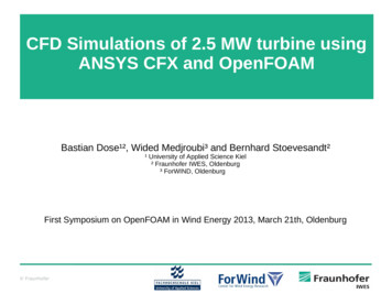
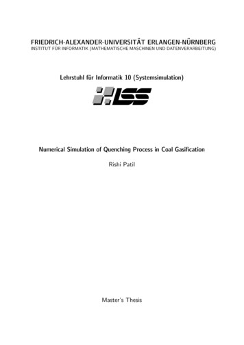
IntroductionC.F.D is used nowadays almost everywhere. It reduces the cost of experiments and allows abetter understanding of the reality. In some areas, such as turbo machinery, using C.F.D can bea challenge.Often in turbo machinery, non rotational parts meet rotational parts. A typicalexample can be a rotor/stator situation, the rotor being the rotational part and the stator the nonrotational one (see fig. 1)Figure 1: Rotor/stator situation.An important question for this case is how is it possible to compute both parts simultaneously?In OpenFoam, there are 3 different way to do so: using a moving mesh ( principle used in icoDyMFoam for incompressible, nonturbulent flow and in turbDyMFoam for incompressible, turbulent flow)defining multi reference frames (the idea behind MRFSimpleFoam, for incompressibleturbulent flow)GGI ( General Grid Interface), still in development.The goal of this tutorial is to give a better understanding of the moving mesh (particularly thesliding interface) and multi reference frames by pointing out some of the particularities for thedifferent solvers. In order to do so, a common case will be used, the mixer2D.3
This tutorial uses both the Open-C.F.D version of OpenFoam 1.4.1 as well as the developmentversion created by Hrvoje Hjasak, named OpenFoam 1.4.1-dev.Both versions can be found in the Chalmers catalog at the following address: cd /chalmers/sw/unsup64/OpenFOAM/In case of running on a 32 bit version the same repertories can be found in cd /chalmers/sw/unsup/OpenFOAM/It is then important to write in the bashrc or cshrc file the 2 following lines:For a 64- bit machinevi /.bashrc. OpenFOAM-1.4.1-dev/bashrc# . FOAM-1.4.1/bashrcFor a 32 bit machine.vi /.bashrc. enFOAM-1.4.1-dev/bashrc# . AM-1.4.1/bashrcRemember then to switch between the two lines if using the development version instead of theOpen C.F.D version.Dynamic mesh changes or sliding interface.There are three different kinds of mesh modifiers available in OpenFoam: attach/detach boundary: this mesh modifier is taking a face and separates it into twodifferent boundary faces, that will be detached and attached againthe layer addition-removal: a layer addition/removal mesh modifier will add a layer ofcells in front of it once the thickness goes over the given threshold and remove a layerof cells if the layer thickness goes below the minimumthe sliding interface: the idea behind the sliding interface is that the mesh is made oftwo different pieces that will be merged. In order to do so, a set of boundary faces oneach side is listed.The sliding interface is the most complex of all the mesh modifiers, but it is the most completeone. The code behind the sliding interface is too big to explain it all in this tutorial, so the maingoal of this tutorial is to give some hints on how it works and where to find the different partsthat are used in the sliding interface, and ultimately point out some important assumptions.4
Short explanation of the sliding interfaceAs explained above, the idea of a sliding interface is to create a mesh in two pieces and identifytwo patches facing each other. A sliding interface should then operate on patch faces in thefollowing way: project all points of the “slave” patch onto the master. The rule is that a master patchpreserves its shape. Most of the time if one part is not moving and the other onerotating, the rule is that the rotating one is the slave one. identify the part of the patches where master and slave overlap. For those faces, theoriginal master and slave boundary should be replaced by a set of faces internal to themesh. if there exists a part of the master part which is uncovered, it should remain in themaster boundary patch and support the specified boundary condition. the same applies for the slave patch if the two meshes move relative to each other, the sliding interface should be able torecover the original definition(faces) and re-couple the meshes.All those topological changes in the mesh are done through 9 basic operations which allow allpossible changes: add/modify/remove point, face or cell. The classes that describe this live v/src/dynamicMesh/polyTopoChangeAll those changes happen during the simulation, and the user shouldn’t have to worry aboutthose topoActions. At each time step, the job of a mesh modifier is then to decide whether itwants to change the mesh topology, and if yes, fill in a polyTopoChange with topoActions thatdescribe the change.Example using the solver icoDyMFoamTo see how the sliding interface is used, an example called mixer2D is used. This example canbe found in the tutorials of the OpenFoam-1.4.1-dev.The first step is to copy it into your run catalog, after having checked that the bashrc file pointsout to the development version.cp -r orials/icoDyMFoam/mixer2D/ /OpenFOAM/username-1.4.1-dev/run/icoDyMFoam is a solver based on icoFoam. The major changes between icoFoam andicoDyMFoam can be investigated with the linux command diff:cd /chalmers/sw/unsup/OpenFOAM/OpenFOAM-1.4.1-dev/ applications/solvers/incompressiblediff icoFoam/icoFoam.C icoDyMFoam/icoDyMFoam.C moreThe main differences lie in the updating of the mesh at each time step. Looking at the userfolder in the run/mixer2D catalog, there is a new dictionary called dynamicMeshDict. Thisdictionary defines the movement of the geometry:5
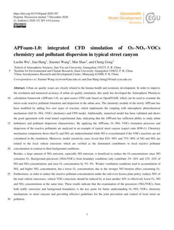
dynamicFvMeshLibs 1("libtopoChangerFvMesh.so");//call a dictionary whenneeded.dynamicFvMesh//class that defines coordinateSystem{typecylindrical;origin(0 0 0);axis(0 0 1);direction(1 0 0);}rpm10;slider{inside insideSlider;outside outsideSlider;//coefficients that defines therotationthe two different sliders definingwhich part of the mesh rotates}}The coordinateSystem defines the type of system we are in: in this case the system iscylindrical, its origin is (0 0 0) the axis of the rotation is z. Using a cylindrical system, oneneeds three coordinates: r,z,ө. The direction gives an axis that defines this angle. The definitionof the direction does not matter so much, as long as it has the right angle with the axis ofrotation, that is to say if the axis of rotation is z, then all axis perpendicular to z can be definedas direction.The two different sliders are important as well, they define the rotating part. Per definition, aswritten in the code, inside defines the slider that is moving, and outside the one that is fixed.There are at the moment 5 different kinds of topoChanger in OpenFoam, and they can be foundin oChangerFvMesh.Those classes define the change (rotation translation or else) that the geometry and thereforethe mesh will go through.If computing it in the usual way,blockMesh . mixer2DicoDyMFoam . mixer2DYou can see the mesh moving as it does along the slider in figure 3.In order to know exactly which part of the geometry is to be modified, the cells and faces thatare concerned are investigated, and then gathered together as zones. This is a very importantand recurrent way of programming and gathering all parts of mesh that one wants to play with.The same way of programming is used in the multi reference frame.6
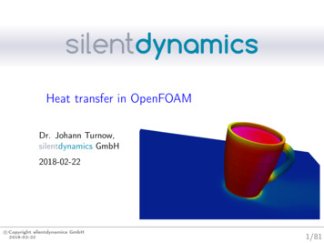
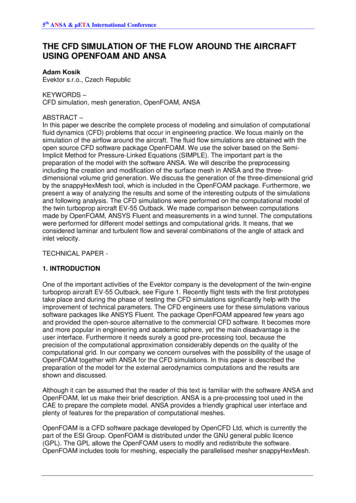
The time folders are written as described in the system/controlDict. Inside those folders, onecan have a look at the file inside polymesh: vi time/polymesh/meshmodifiers.gz.In this file the master and slave parts are defined as well as the kind of mesh modifier used andother properties. It is wise not to change this file.ResultsFigure 2: geometry of the mixer2D7
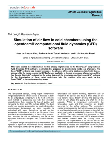
Figure 3: caption of the moving meshComputing the same example in turbDyMFoamUsing the sliding interface in turbDyMFoam is pretty straight forward once the basics oficoDyMFoam has been understood.One can look at the difference between the both solvers, doing:cd pplications/solvers/incompressiblediff turbDyMFoam/turbDyMFoam.C icoDyMFoam/icoDyMFoam.C moreThe main differences come from the fact that a turbulent model is introduced, and that the PISOis used instead of SIMPLE.Some modifications have to be done in the mixer2D case to be able to run it in a turbulentmodel.It is wise if one wants to start a new case to start with a scratch case, which is to say to copyagain the mixer2D case from the tutorials place. This ensures you that you get the minimumneeded, and no other files that can come from blockMesh or some other commands.cp -r orials/icoDyMFoam/mixer2D/ /OpenFOAM/username-1.4.1-dev/run/mixerTurb2DThis case will of course not work properly if you doblockMesh . mixerTurb2DturbDyMFoam . mixerTurb2D8
The reason is quite simple: there is nothing written yet that defines the turbulent model. It is justa matter of adding the right files.OpenFoam is helpful while doing it; the error message are usually very explicit and allows youto do this procedure quite fast.Particularities of a mesh modifierThere are some things that one has to be aware of when using a mesh modifier: The boundary conditions are not rotating with the mesh, they are independent. That is tosay if you want to get a swirl in a cylinder, you will have to specify a radial velocity todo so.The origin of the geometry plays a very important role in the moving mesh: in the classmixerFvMesh, located in c/topoChangerFvMesh/mixerFvMesh, there is a piece of code that indicates thefollowing:// Mark every cell with its topological regionregionSplit rs(*this);// Get the region of the cell containing the origin.label originRegion rs[findNearestCell(cs().origin())];labelList movingCells(nCells());label nMovingCells 0;forAll(rs, cellI){if (rs[cellI] originRegion){movingCells[nMovingCells] cellI;nMovingCells ;}}This code basically tries to find the nearest cell to the origin and group all the cells around in adetached zone around the origin.This is an important assumption, which means that you have to have the origin at the sameplace as the geometry that is moving. Right now, if this is not the case, there are two solutionsavailable to go around the problem: Using the openFoam transformPoints, so that you move your geometry untilthe origin is in the desired region. transformPoints is a command in9
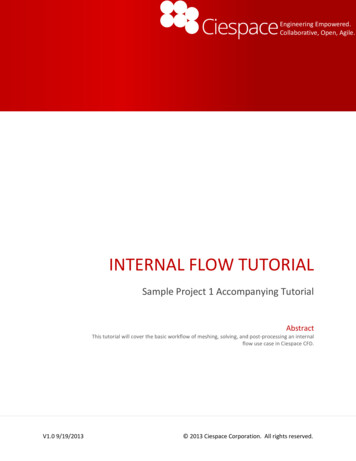
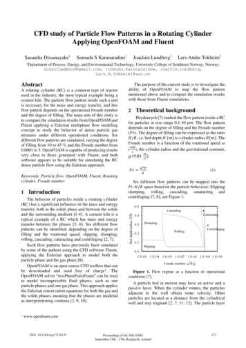
OpenFoam that allows a change in the geometry without having to rewrite theblockMeshDict.It is used the as showed: one has to be careful to be in the run catalog:transformPoints . testCase –translate vectorHowever, despite the easiness of this method it could sometimes be notpossible or practical to translate a geometry as desired due to somerestrictions. Using the dynamicMeshDict, changing the origin in this dictionary. This is aswell an easy way to solve this problem.It is then very important to be aware of this assumption. Before running a sliding interface case,two things are important to check: where is the geometrical origin, and is the slidinginterface defined correctly.The sliding interface is as well a big factor in the definition of the moving part: per definition,the slider that is linked to the moving part of the mesh is called inside and the fixed part of theslider is called outside. If one makes a mistake and do the opposite, the wrong part of the meshwill turn.Figure 4: result of the origin being in the wrong part of the mesh10
Figure 5: result of writing the wrong slider as inside: the outer part is rotatingConclusions and remarks about the mesh modifiersThe sliding interface is a part of OpenFoam developed by Hrvoje Jasak in 2005. It is a veryimportant part of OpenFoam development that allows new freedom in computing, especially inturbo machinery. Due to the free access of OpenFoam, this code is being developed andimproved almost every month, which makes it strong. When using this part of OpenFoam, it isbetter to be aware of what is happening on the forum, and do regularly updates on svn.The machinery behind dynamic mesh is very well written and really nicely organized, but thereare still some drawbacks that one has to keep in mind. The mesh modifier operates at each timestep of a computation, which means that at each time step, OpenFoam looks for faces that haveto be detached and attached. The bottom of this is that it is quite heavy, and it can take quite alot of memory. The other important drawback is that the dynamic mesh is not working inparallel, which limit the computation power when using a big mesh. Parallel computation willcome in the coming years, but at the moment the sliding interface is available only on oneprocessor.11
Multi reference frames, or MRFSimpleFoamMulti reference frame is a part of OpenFoam developed by OpenCFD. You should then switchin your bashrc file to the OpaenFoam version 1.4.1.The tutorial that will be used to explain MRFSimpleFoam can be found as followed:cp -r ls/MRFSimpleFoam/mixerVessel2D/ .The Multi Reference Frames solver is not compiled in any of the used version of OpenFoam.The source code can be found ials/MRFSimpleFoam/.In order to use this code and to compile it, copy it in the run catalogue and use wmake.cp -r .4.1/run/cd MRFSimpleFoamwmakethe Multi Reference Frame solver is now available, and one can check which version ofOpenFoam is used by doing which MRFSimpleFoamMixerVessel2DMixerVessel2D is the same geometry as mixer2D. By digging in the mixerVessel2D one cansee the same folder than usual, the zero, constant and system folders.In the constant folder, you will find a dictionary named dynamicMeshDict. This is the samedictionary than the one used in the sliding interface example. This file is here just becausemixerVessel2D is a tutorial that has been developed starting from the icoDyMFoam tutorialmixer2D, and dynamicMeshDict has not been deleted as it should have.It is one of the things one has to be careful in OpenFoam: OpenFoam is very helpful due to itsopen code, and it is quite easy to use a old piece of code and create a new piece that will fit aspecial case, but it requires attention; some files can be generated by blockMesh or the solvericoDyMFoam or else, and once generated, you will get an error message if trying to run thesame solver again.One good way to know whether a file is needed or not is to rename it so that OpenFoam will notrecognize it. This way, if OpenFoam complains, then the file is needed, and if not, the filecomes from somewhere else.In the mixerVEssel2D case, dynamicMeshDic comes from mixer2D and is definitely notneeded, so one can docd constantmv dynamicMeshDict dynamicMeshDictIcoDYMFoamLaunching mixerVessel2D12
MRFSimpleFoam is a solver derived from SimpleFoam, so it is an incompressible turbulentmodel.Its purpose is to define one or more frames that will be attributed to different parts of thegeometry (defined as patches). In the case of the mixerVessel2D, which has the same geometryas the mixer2D, there are two different parts: one is rotating, and is called patch rotor in theMRFSimpleFoam case, and one is non rotating, called stator. When computing, the mesh willthen not move, and we will spare the time and memory used in the sliding interface to recalculate the new position of the mesh. Instead, in MRFSimpleFoam, the different equationswill be calculated in two different frames, Cartesian and cylindrical.Those different frames are defined in mixerVessel2D/constant/MRFZones. In the mixer case,there is only one reference frame:1(rotor{patches (rotor);origin origin [0 1 0 0 0 0 0] (0 0 0);axis axis [0 0 0 0 0 0 0] (0 0 1);omega omega [0 0 -1 0 0 0 0] 104.72;})This file defines which patch is concerned about this frame, the origin axis and rotation speed ofthe rotor. This means that the equation will use those indications when computing in the cellsbelonging to the patch rotor, by adding the Coriolis force.The Coriolis force is added in the code in the code MRFSimpleFoam.C :// Pressure-velocity SIMPLE corrector{// Momentum predictortmp fvVectorMatrix UEqn(fvm::div(phi, U) turbulence- ();solve(UEqn() lScalarField rAU 1.0/UEqn().A();U rAU*UEqn().H();UEqn.clear();But the question then is: how can OpenFoam know which cells belong to the patch rotor?This is defined in the file makeMesh in mixerVessel2D/makeMeshThis file is generated the mesh and the files needed by MRFSimpleFoam.It is divided into 6 steps:13
m4 constant/polymesh/blockmeshdict.m4 constant/polyMesh/blockMeshDict)the mesh was generated by m4 and using the command m4 it is compilated inblockMeshDict then, it is a standard mesh generation on the basis of blockMeshDictblockMesh . mixerVessel2D generation of a set of cells belonging to zone rotorcellSet . mixerVessel2D then it takes the cells obtained above, and generates faces of those cellscp system/faceSetDict rotorFaces system/faceSetDictfaceSet . mixerVessel2D take faces created above and deletes boundary facescp system/faceSetDict noBoundaryFaces system/faceSetDictfaceSet . mixerVessel2D finally it writes faceZones for the mesh on the basis of the faces that are leftwith the operation abovesetsToZones . mixerVessel2D –noFlipMapAll those operation can be run in the same time by doing:cd mixerVessel2D./makeMeshTutorial: improvement of the mixerVessel2DTo see if the basics of the MRFSimpleFoam solver are understood, a little experience can bemade: let’s try to make the other part of the mixerVessel2D, the stator, a rotating part as well.This exercise will underline which parts matter when creating a new reference frame.Basically, what is to be done is to creates a new reference frame in MRFZones, and to gatherthe information about this part in a new sets.Conclusion about MRFSimpleFoamMRFSimpleFoam is in itself a bit easier to work with than the mesh modifiers. It does not needto re-calculate at each time step the position of the moving mesh, as the mesh stays still. It isjust adding the Coriolis term when a new reference frame is added. This makes theMRFSimpleFoam solver only useful when dealing with rotational parts. If ones wants tocompute a translating object, then MRFSimpleFoam is not an option. MRFSimpleFoam canunfortunately not be used in parallel neither, so that the possibilities with this solver are limited.An other version of the multi reference frame solver will be out soon, developed by thecompany Hydro Quebec in Canada. It is using a totally different approach than the one showedabove. This version will be released in the coming year.Conclusions14
Two different ways to deal with rotating parts have been shown above. Using those two solversrequires a little knowledge in C , and some time is needed in order to grasp the methodologyof both solvers. But once this time has been invested, the mesh modifiers and the multireference frames solvers show a very wide panel of possibilities. However, being unable to usethose solvers in parallel is an important drawback, and those solvers can not be used for bigmeshes.Hydro-Quebec, represented by Martin Beaudoin, in collaboration with Håkan Nilsson inChalmers are working right now on a new interface, called the GGI ,General Grid Interface.This interface is very promising as it does not re-position the mesh at each time step. One of thegoals as well is to make it work in parallel. A functional version of it will be presented in theOpenFoam conference in july in Milano.The release of this new interface should occur in thefollowing year.References1. http://openfoamwiki.net/, and more accuratelyhttp://openfoamwiki.net/index.php/HowTo setting up dynamic mesh cases2. http://foam.sourceforge.net/doc/Doxygen/html/3. s.cgi15
Open C.F.D version. Dynamic mesh changes or sliding interface. There are three different kinds of mesh modifiers available in OpenFoam: attach/detach boundary : this mesh modifier is taking a face and separates it into two different boundary faces, that will be detached and attached again