Transcription
T H E M A G A Z I N E O F 7 x 2 4 E X C H A N G E I N T E R N AT I O N A LFALLDATACENTERCOOLINGENERGYBASICS07THE USE OFOUTSIDE AIRECONOMIZERSINDATA CENTERENVIRONMENTSAN ISOLATED-PARALLEL UPSSYSTEM FOR A LARGE DATA CENTER
Contentswww.7x24exchange.org6An Isolated-Parallel UPS System for a Large Data CenterDIRECTORS & OFFICERSChairman of the BoardRobert J. CassilianoBusiness Information Services, Inc.(201) 672-0630President & Chapter RepresentativeWilliam LeedeckeVanguard(610) 669-570710Data Center Facility Control Systems:Commercial VS. Industrial14Data Center Cooling Energy BasicsVice PresidentRoy L. ChapmanAmerican Express(602) 766-6502Vendor RepresentativeDouglas H. SandbergASCO Power Technologies(973) 966-2079DirectorDavid SchirmacherGoldman Sachs & Co.(212) 357-748218The Use of Outside Air Economizers in Data CenterEnvironments26Fan Energy Reduction in an Existing Data Center –A Case StudyAdministrative DirectorKathleen A. Dolci(646) 486-3818 x103kathleen@7x24exchange.orgMembership & EducationTara Oehlmann, Ed.M.(646) 486-3818 x104tara@7x24exchange.orgConferencesBrandon A. Dolci, CMP(646) 486-3818 x108brandon@7x24exchange.org3036Designing Fault-Defiant Electrical Power SystemsFor Data CentersInside 7x24322 Eighth Avenue, Suite 501New York, NY 10001(646) 486-3818FALL 20073
ANI S O LA T E D - PA R A LL E LUP S S YS TEMF O R A L A RGE D A TA C EN TERby Mike Mosman, PEDuPont Fabros, a leading owner, developer, operator and manager ofwholesale data centers, maintains several large data centers which itprovides to tenants under long-term leases. In 2006 they wereplanning a new facility at their data center campus in Ashburn,Virginia. DuPont Fabros’ data center design standards require thecritical power delivery systems in their facilities be flexible enough tomatch individual tenant load requirements, while providing faultisolation that would limit internal disturbances to a single tenant. Inaddition to the technical requirements for the critical power systems,the overall facility infrastructure must be designed to be economical forboth capital and recurring costs.Existing DuPont Fabros data centers in their campus have rotaryflywheel type Diesel-UPS modules arranged in isolated-redundantconfigurations. These UPS modules are applied in groups of 8 to 12Diesel-UPS modules with two modules designated as redundant units.These systems are designed with static transfer switches to transfercritical load from a failed primary module to a redundant module. Inorder to achieve the fault tolerance requirements of the DuPont Fabros6FALL 2007design standards, UPS modules are dedicated to specific tenant areasfor fault isolation. Rotary Diesel-UPS technology as implemented inthese facilities provides an efficient and resilient system that iseconomical and compact compared to an electrical systemincorporating large system-redundant static UPS systems with batteries.For DuPont Fabros the iso-redundant systems have provided a highlevel of resilience while reducing capital and maintenance costs.LESSONS LEARNEDIn operating their existing facilities, DuPont Fabros identified certainaspects of the isolated-redundant UPS systems they wished to improveupon. For instance, the reliance on static transfer switches to providethe system redundancy makes isolated-redundant systems susceptibleto the problems inherent in the coordination of UPS outputcharacteristics and STS input tolerances. Another issue identified isthat excess capacity in the isolated modules can not be easily usedfor delivery of additional power to other tenants. Likewise, the totalredundancy in the system is always limited to the number of
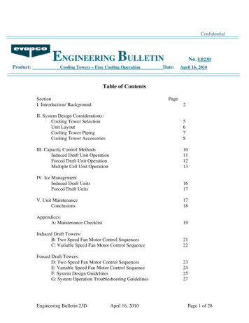
An Isolated-Parallel UPS System for a Large Data Centerredundant modules that are dedicated to the alternate source of thestatic transfer switches.In order to serve their growing customer base, DuPont Fabrosmade the commitment to build their new facility to an unprecedentedscale. Their engineer, CCG Facilities Integration Incorporated,programmed a 300,000 square foot building with 170,300 squarefeet of raised floor divided into 16 computer rooms, each of which canbe further partitioned into one, two or four spaces. Allowing forredundant capacities, a 40 MW UPS system, a 17,000 ton chillerplant, and an 80 MVA electrical service with 72 MW of backup dieselengine-generators was programmed to meet the maximumrequirements of the tenants that would occupy these spaces.The programming and design phases of this new facility gave itsowners an opportunity to review the their previous data centers, andconsider ways to improve future facilities. Instead of an iso-redundantUPS configuration, DuPont Fabros agreed to implement an innovativeintegration of parallel-redundant and isolated-redundant UPSconfigurations developed by CCG called an Isolated-Parallel (IP) UPSconfiguration. An IP system had never been used in the US, but it heldthe promise of providing some additional benefits over their priorcritical power delivery systems.IP BASICSAn Isolated-Parallel UPS system is made up of a group of Diesel-UPSmodules which share a common paralleling bus, or IP bus. Eachmodule within an IP system has a utility input backed up by a singlediesel engine-generator, and a reactive choke and synchronousalternator combination for power conditioning. The alternator has acoupled flywheel for energy storage to be used as the ride-throughpower source between utility outage and diesel engine-generatortakeover. Each module has an output bus for its dedicated criticalloads. Each critical output bus is also connected to the IP bus throughanother reactive choke (IP choke) which allows real power to flow, butrestricts high fault kVA flow due to the reactive nature of fault currents.The utility input and diesel engine-generator associated with eachmodule can also be used supply essential mechanical equipment thatdoes not need ride-through power.Two IP systems, each with 16 modules were designed by CCG forDuPont Fabros’ new facility. The Diesel-UPS modules are eachdesigned to serve a combination of critical and essential loads, whileproviding continuous backup to the utility power. Electrical service isbrought into the building via 16 pad-mounted transformers rated 5MVA each. A service transformer secondary voltage of 600 volts isused to reduce the size of feeders and breakers in the facility. The2250 kW engine-generators, which are part of the Diesel-UPS systemand installed within the building, also operate at 600 volts. As anadded reliability enhancement the entire 600 volt system is highresistance grounded to allow the system to operate unaffected by aline-to-ground fault anywhere on the system.The critical power distribution panels are capable of handling up to200% of the their normal load, enabling DuPont Fabros to provide “A”and “B” distribution points within their tenant’s computer rooms andnot be concerned about an uneven A/B split of critical power demand.While Static Transfer Switches are not required to produce theredundancy between “A” and “B” UPS modules, they may be used ifrequired for a specific tenant application. An even greater advantage tothe owner and landlord is the ability to handle an “overload” by one ofhis tenants. As long as the total load in the building remains belowthe IP system’s redundant load point, any computer room may exceedits allotted power level up to the air-conditioning capacity providedwithin the space. Since load is leveled across all connected modulesin the IP system, the excess requirement of the overloaded computerroom is automatically made up by those computer rooms which areyet below their load allotment.IMPLEMENTING A NEW CONCEPTPiller Power Systems was chosen as the supplier for the Diesel-UPSflywheel modules, engine-generators and associated switchboards. Aspart of their scope of work Piller commissioned a computer model of a16-module IP Diesel-UPS system from DBR Consult, an independentconsulting firm in Germany. The computer model was used to predictthe load flow and transient stability of 16 generators and 16flywheel/alternators operating on a common parallel bus through 16chokes, and serving 16 independent steady state and transient loadsof varying amount ranging from 0 to 200%. The results of Piller’smodeling indicated very stable operation and controlled load flowwithin the normal ratings of system components.To implement CCG’s IP design concept, Piller’s systems engineersand project management specified the required parameters of systemcomponents, and coordinated their delivery and testing. They designedthe control systems necessary for the integrated operation of the UPSmodules, engine-generators, and switchboards. Unique and innovativeschemes were developed to provide independence between Diesel-UPSmodules while controlling load flow especially when modules are indifferent modes of operation.In order to verify the IP system, CCG and DuPont Fabros requiredPiller to assemble four Diesel-UPS modules, four engine-generatorsand four sets of module switchboards into a 4-module IP systemwithin their New York testing facility. A comprehensive factory test wasconducted at rated load and witnessed by DuPont Fabros and CCG.The test results agreed very closely with the computer model. A furthertest was conducted on a prototype of the IP choke at a high-currenttest lab that verified the reactive chokes on which the IP systemdepends for its isolation would not saturate and lose impedance undera fault condition. The first Isolated-Parallel UPS system had apromising start.A DESIGN REALIZEDConstruction of the new facility, designated Ashburn Corporate Center#4, or ACC4, began in June, 2006. DuPont Fabros engaged HolderConstruction as the general contractor with Dynalectric as the electricalsubcontractor. By the end of June, 2007 the first 16-module systemwas fully commissioned. The commissioning effort was specificallydesigned to demonstrate the special features of an IP configurationthat, combined, differentiate it from iso-redundant or standard parallelredundant UPS configurations. These are: Load sharing and equalization among all modules. When brieflyon flywheel as the critical power source, or while on diesel enginegenerators as the backup power source, the critical loads are evenlydistributed across all units connected to the IP bus, even when criticalloads vary from 0 to 200% on any unit’s output bus.FALL 20077
An Isolated-Parallel UPS System for a Large Data Center Fault isolation to a single output bus. A fault anywhere on thesystem will at most affect only one Diesel-UPS module’s critical outputbus. The voltage on all other critical busses remain within the ITI(CBEMA) curve. Fault currents everywhere in the system are limited bythe IP chokes to less than 100,000 amps rms, even with 16diesel generators connected. Bypass to the common IP bus. If a UPSmodule fails the output is not dropped, butrather is sustained by power flow through itsIP choke from the IP bus. An automatic ormanual initiation of the bypass circuit forthat unit will transfer its critical load to theIP bus directly where it will be sharedequally by all other modules connected tothe IP bus. Distributed redundancy. There is nodesignated redundant module. All modulesshare the total critical load, and the amount ofredundancy is merely the difference between thetotal load and the total capacity. Independent modules. While the IP system has a central MasterController, it is not required to control load flow, or respond to outagesand failures. All modules operate with completely independentindividual controls, and no single point of failure was discoveredanywhere in the system.8FALL 2007The results of site testing done during the commissioning processonce again agreed with the predictions of the computer model. Theload flow analysis was exactly comparable to real measured values.Furthermore, the entire system was very stable under transientperturbations. Even so, the full system commissioning testsrevealed the need for some minor control componentadjustments. After these changes the IP system’sspecified robustness and fault tolerance was fullyrealized. The new IP system has reliably andrepeatedly demonstrated its ability to start andparallel 16 engine generators on the commonIP bus well within the spindown time of theUPS flywheels at full building load. It is alsoable to seamlessly handle engine start andsynchronizing failures. By the end of thecommissioning effort the Isolated-Parallel UPSsystem configuration was a proven concept.The inclusion of the IP design in its portfoliosupports DuPont Fabros’ commitment to build theirdata center infrastructures to the highest specificationlevel commercially available, while providing battery-freemaintenance, distributed redundancy, load sharing flexibility and faulttolerance.Mike Mosman, PE is Vice President of CCG Facilities Integration Incorporated.He can be reached at mmosman@ccgfacilities.com.
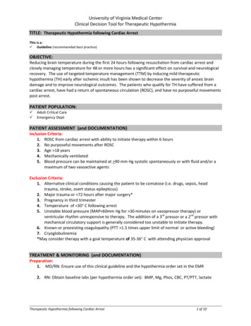
DATA CENTER FACILITY CONTROL SYSTEMS:by Steven Blaine, PESystem uptime is the crucial objective of data center operations yet,unlike other mission-critical facilities, data centers are typically builtwith commercial DDC (Direct Digital Control) control systems.Consider this: a study at Lawrence Berkeley National Laboratoriesidentified controls as the single largest source of HVAC systemproblems (see below). The biggest threat to data center availabilitymay be the control system.densities increase, the response time will decrease to just a fewminutes with an even higher temperature rise. This is enough toseriously disrupt or damage sensitive computer equipment.Figure 2: Continuous Cooling is Required for Continuous Availability – From theUptime Institute (3)Figure 1: Frequency of common problems encountered in a 60 building studyperformed by Lawrence Berkeley National Laboratories (2)It’s time for owners and system designers to consider the benefitsof industrial PLC (Programmable Logic Controllers) / SCADA(Supervisory Control and Data Acquisition) control systems.Building automation controls are generally regarded as a simplersubset of process control. In most buildings, thermal mass is large,response times are slow and the consequences of system failure areusually not severe. But in data centers, this is not true. If the controlsystem does not respond quickly and appropriately, a data center mayexperience a destructive and rapid failure – even if redundant chillers,air handlers and power sources have been installed.Data centers have unique and demanding HVAC requirements. Onestudy by ComputerSite Engineering showed that during a coolingfailure, the air temperature in a modestly loaded data center could seea 25 F temperature rise in only 10 minutes (see below). As heat10FALL 2007In spite of these stringent requirements and the seriousconsequences of failure, most data centers are built with the samecommercial DDC style control systems used in office buildings. This isin contrast to other mission-critical environments such assemiconductor cleanrooms, or pharmaceutical laboratories, whereindustrial controls such as a combination of PLCs with SCADAcomputers or even DCS (Distributed Control Systems) systems performmany of the same functions.Cost DifferencesA rule of thumb for control systems is this: industrial controls totalinstalled cost is approximately 2000/point. Commercial systems costapproximately 1000/point. For reference, a recent data center projectwas completed with 500 I/O points. This represents a difference of 1M vs. 500K. This does not consider the difference in maintenanceand service contract costs (which is typically higher for commercialcontrols) but is a reasonable idea of the difference in up-front costs.So, besides price, what differentiates industrial from commercial stylecontrols? Following is an overview of the five main areas wherecommercial and industrial systems differ.
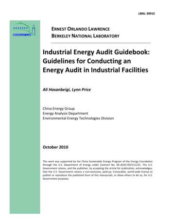
Data Center Facility Control Systems: Commercial VS. IndustrialQuality of DevicesAutomated control starts with the measurement of ambient and systemparameters. The measurement process is a chain of sensors,transducers, analog to digital conversion and software processing.Errors and uncertainties at any point in the chain affect the accuracy ofmeasurement and ultimately, the capability of the control system. Forboth DDC and industrial control systems, the largest source ofinaccuracy is typically the sensor itself.Sensors for temperature, humidity, flow, pressure, voltage andcurrent are all used in data centers. Commercial sensors have aminimal accuracy requirement but are normally chosen for their lowcost and sometimes, architectural attractiveness. Industrial controlsgenerally use more accurate and robustly packaged devices.DDC systems can use directly connected resistance measurementsfor temperature, and 0-10 VDC or 4-20 ma for other input signals.Industrial systems nearly always specify 4-20 ma current loops whichare more impervious to electrical noise and wiring degradation. Incommercial installations, sensor wiring is not always placed inconduit. Industrial sensor wiring is typically in conduit where it isprotected from physical damage and electrical interference. At thecontroller, input signals are converted from analog to digital withdifferent levels of precision. Commercial controllers have 10 or 12 bitresolution. Industrial controllers have 14 or 16 bit resolution. Whilenot always significant for environmental parameters, higher resolutioncoupled with more accurate sensors and lower noise signals meansbetter measurement.normally provided for PLCs. PLC manufacturers do offer a commonsoftware product that typically programs all of the PLCs they sell.There has also been a significant effort to standardize programminglanguages used by all PLCs. IEC 1131-3 is the international standardfor programmable controller programming languages. This specifiesthe syntax, semantics and display for a suite of PLC languages. Theresult is that today, most PLC programs share a common look andfeel regardless of the manufacturer. In the USA, PLCs are usuallyprogrammed in ladder logic. This visual language is quite familiar toelectricians. In fact, its name comes from the hardwired relay controldiagrams used to run machinery that look like ladders.System PerformanceThe two types of systems conceptually can look very similar. Thedifference is performance. Industrial systems are designed for “realtime” control. Like a DDC, a PLC program looks at sensor input,performs logic or calculations and writes outputs. The speed ofprocessing and communication in PLC systems is faster than DDCsystems. This allows inputs to be read from anywhere in the system,logic solved, and outputs written to anywhere else in the system – inreal-time.Controllers and SoftwareAll input and output signals eventually connect to some sort ofcontroller – the central element of any control system. Commercialsystems use a mix of “unitary” controllers to control a single piece ofequipment and larger building controllers for facility wideprogramming tasks. Industrial systems use PLCs which also come ina range of sizes and intended applications. The differences betweenthese controllers can be discussed in terms of form factor andphysical robustness, I/O type and capacity, and processorprogramming capability and flexibility. These differences are discussedfurther in the long version of this paper.Programming CapabilityDDC programming languages have evolved from text based versionsof high level computer languages like BASIC and PASCAL intographical drawing versions. A DDC programmer creates a program orcontrol strategy by placing a box representing the function block onthe screen and connecting the inputs and outputs appropriately.Once these graphical representations are complete, they aretranslated or compiled into machine readable code and downloadedto the controller. Each vendor has their own programming languagesthat are specific to their equipment – sometimes different softwareproducts for different controllers. DDC vendors often supply controlprogram templates optimized for specific HVAC functions. Thetemplates can match standard HVAC applications quite perfectly.Programming a PLC is very different from programming a DDC.Like DDC manufacturers, PLC vendors each have their ownprogramming software. In contrast, programming templates are not12FALL 2007Figure 3: Explanation of PLC Scan RateThe time it takes for a PLC to read inputs, solve logic, write outputsand perform overhead functions is called “scan rate”. Scan rates forPLCs, even in large programs with distributed I/O, are generallymeasured in milliseconds. DDCs have program execution frequenciesmeasured in seconds.PLC and DDC programs differ fundamentally in flexibility. Theprogramming functions in a PLC are more numerous and powerful.There is a richer instruction set for math, logic and bit manipulation.Many PLCs allow encapsulation of instructions to create user definedfunction blocks. This is a powerful tool that sophisticated usersleverage to create simple, re-usable code. Finally, modification of PLCprograms can be done “on-line” which means the controllers do notneed to be stopped if the program needs to be changed.System Architecture and RedundancyReliability should consider the dependability of individual items butalso a system in which a failure in one part doesn’t affect others. Withcareful engineering, control systems can be designed for faulttolerance.One method of achieving fault tolerance is to provide distributedcontrol. Valid for either commercial or industrial systems, smallinexpensive controllers can be dedicated to individual machines orprocesses. In this case, the loss of a single controller cannot
Data Center Facility Control Systems: Commercial VS. Industrialshutdown the entire facility. This type of design is called “passiveautomation”. It implies that the system will operate properly even if theautomation system is not performing its function. Ability to “hold last state” – during communication loss orprogramming downloads, this ability can prevent loss of control or alengthy recovery period.Not all situations allow for passive automation. There are caseswhere a single controller must make decisions that require inputs fromor outputs to multiple systems: large area temperature control, powerrestart, load shedding, humidity control, chiller sequencing andpressurization. These should always function continuously. Master/backup loops – critical control loops are sometimesprogrammed so that one controller is the master but a second is thebackup. In case of a controller failure, the loop continues to operate.Instead of distributed control, another method of achieving highreliability is to build a fault-tolerant, redundant control system. Withthis approach, just a few or even one single controller pair can run anentire facility and no single failure can prevent continuous operation. Agood design of this type requires careful consideration of each systemcomponent. These may include redundant controllers, network media,power supplies and SCADA servers. It may also include dual powerfeeds, redundant and separate supervisory networks. PLCs haveevolved sophisticated capabilities in this area but DDCs have not.Other Control System ConsiderationsThe following is a list of features that should be compared whenconsidering a particular architecture or controller for data centerapplications. DDC functionality has increased tremendously in the lastfew years and the latest systems from the leading suppliers canprovide most or all of these features. It still must be said that some ofthese items are more difficult or impossible to accomplish with DDCsystems: Hot swap of modules – PLC modules are often designed to bereplaced under power. This feature prevents the necessity of poweringdown a controller to perform a repair.ConclusionWe have seen how industrial control systems differ from commercialsystems in their use of more accurate and rugged sensors anddevices, signal types and wiring methods. Industrial controllers aremore robust, have higher performance, faster networks and moreflexible programming capability. Redundancy options with industrialcontrols can address the most difficult control issues without relyingon “passive automation”.While both DDC and PLC/SCADA systems are capable of controllingthe facility equipment found in a typical data center, owners andsystem designers should be aware of the differences in performance,flexibility and reliability, and not expect to achieve industrial controlsystem performance on a commercial control system budget.Steve Blaine, PE is an Instrumentation and Controls Specialist with IDCArchitects, a CH2M HILL Company. He can be reached at steve.blaine@ch2m.com.FALL 200713
by Donald BeatyIntroductionThe focus on data center energy is rapidly increasing. Energy Star,EPA, Congress Public Law 109 – 431, ASHRAE, Green Grid, LBNL areall involved in data center energy one form or another.The are many ways to approach energy usage and conservation.Innovation can certainly reduce energy but there is plenty of energysaving opportunity that is relatively easy at the basic level. The basiclevel starts with “right sizing” which applies to both cooling equipmentand cooling systems. This article starts with a practical example of“right sizing” and then describes the following 5 steps to achieving“right sizing” and the associated energy savings. Step 1 – Determine the Actual Maximum Load Step 2 – Determine the Load Profile Step 3 – Determine the Future LoadStep 1 – Determine the Actual Maximum LoadWhat is the maximum load for each piece of equipment? Especially ina multi-vendor environment, this can be quite an undertaking. Typicallythe terms used vary greatly resulting in inherent inaccuracies due to notusing a common baseline and unit (e.g. load for 1 piece of equipmentstated in watts while another piece of equipment stated in amps). Forexample, some terms used to express power or load include: Watts or KW Wiring Amps Amps Step 5 – Equipment and System Selection Circuit Amps Full Load AmpsHow efficient is it to size something 100 times larger than necessary?Will it use the same amount of energy as something that is sizedprecisely for the load it serves? Common sense correctly tells us thatgrossly oversizing is not efficient. A practical example of “right sizing”is to consider various ways to fill a glass of water.OVERSIZING. How much water will actually enter the glass if it isfilled with a fire hose? Depending on how long you try to fill the glass,the entire area around the glass will be covered with the overspraywhich is essentially wasted water. The wasted water is a direct parallelto the wasted energy associated with mismatching the load and thecooling system capacity.RIGHT SIZING. In the same glass example, what if the glass isfilled with water from a sink faucet that is easily controlled; all thewater enters and stays in the glass with no waste. This is an exampleof matching the supply with the need; “right sizing”.WASTE DUE TO POOR CONTROL. Take the glass example still onemore time. What if the glass is filled with a faucet that has anautomatic shutoff? The glass will be filled but you have to move theglass around to re-engage the sensor so that the faucet does notFALL 2007Right sizing is a good energy saver and is easily achievable. Oneway to accomplish this is to use the following 5 steps. Step 4 – Determine the Operating ConditionsPractical Example of Right Sizing14prematurely shutoff. The net result is the glass will be filled but theautomatic shutoff will keep the faucet running for a period of time afterthe glass is filled. This is an example of inadequate control and notsynchronizing the cooling supply with the load. Peak Amps Nameplate Amps Measured Load General Allowance in KW/RackFrequently the nameplate amps are used because it is a numberthat is readily available (attached to the equipment). Unfortunately thenameplate information is a regulatory requirement and is focused onsafety; not on accurately characterizing the load.Typically the nameplate amps grossly overstate the load. Tocompensate for this, many apply an adjustment factor (e.g. 40 to60%). There is great inconsistency in the measured load versus thenameplate value and therefore a standardized adjustment factor canbe inaccurate (oversize or undersize).The most effective approach to identifying equipment load is torequest an ASHRAE Thermal Report for each piece of equipment. Thisreport identifies the measured load (heat release) in watts andprovides this information for multiple configurations of the equipmentsuch as number of processors, amount of memory, or the amount ofhard disks.Step 2 – Determine the Load ProfileImagine looking at the compute load or workload for an entire datacenter in 5 minute increments across an entire year. It is hard toimagine that there would be no fluctuation in load and easy toimagine significant fluctuation.
Data Center Cooling Energy BasicsTypically within a data center, there is morethan one software application running. Furtherthe activities and load on each application areoften varying. This compute load profile is alsocomplicated by software upgrades andapplications that are installed but not servingload (e.g. cannot run until all sites have thesoftware installed).The cooling system is not only impacted bythe compute load but by climate as well. It isvery beneficial to produce annual load profilecurves for the compute load, climate, and acomposite of compute load and climate. Thesame profile curves should be provided for anhour period and day in addition to the annual.These profiles should be produced even ifthey are not much more than educated guessesusing minimal input from IT operations, etc.Step 3 – Determine the FutureLoadFigure 1 shows an ASHRAE Thermal Report for the IBM model 520. Where a Thermal Report is not available,s
6 An Isolated-Parallel UPS System for a Large Data Center 10 Data Center Facility Control Systems: Commercial VS. Industrial 14 Data Center Cooling Energy Basics 18 The Use of Outside Air Economizers in Data Center Environments 26 Fan Energy Reduction in an Existing Data Center – A Case