Transcription
Application ReportSLLA414 – August 2018High-Speed Layout Guidelines for Signal Conditionersand USB Hubs. High Speed Signal ConditioningABSTRACTAs modern interface frequencies scale higher, care must be taken in the printed circuit board (PCB) layoutphase of a design to ensure a robust solution. This document focuses on high speed layouts guidelinesrelating to USB, USB Hubs, HDMI, DisplayPort, PCIe and SATA.12345ContentsIntroduction . 3Protocol Specific Layout guidelines . 3General High-Speed Signal Routing . 6High-Speed Differential Signal Routing . 14References . 24List of Figures.1Inter vs. Intra Pair Skew2Serpentine Trace Geometry . 73Return Path . 74High Frequency Return Path . 85Routing Across a Split Plane . 86AC Capacitor Across a Split Plane . 97Routing Across Different Reference Planes . 108Routing Across Different Reference Planes with AC l Pair Via Return path Without GND Vias .Differential Pair Via Return path With GND Vias .VCC Reference Plane .Differential Pair Spacing Next to Other Signals .Differential Pair Spacing Next to Clock or a Periodic Signal .Differential Pair Symmetry .Receptacle Stubs Mitigation .Vias With Long Stubs .Vias With Short Stubs .Long Vias With Back-Drilled Stubs .Reducing Stub Length .Via Anti-Pad .AC-Coupling Capacitor Placement .Void Below Surface Mount Devices .Signal Bending Rules .610111213141415161718192020212222List of Tables1Critical Signals . 3SLLA414 – August 2018Submit Documentation FeedbackHigh-Speed Layout Guidelines for Signal Conditioners and USB HubsCopyright 2018, Texas Instruments Incorporated1
www.ti.com234.Possible Board Stack-up on a Four-Layer PCB.Other Example PCB Stack-ups.Possible Board Stack-up on a Six-Layer PCB232323TrademarksAll trademarks are the property of their respective owners.2High-Speed Layout Guidelines for Signal Conditioners and USB HubsCopyright 2018, Texas Instruments IncorporatedSLLA414 – August 2018Submit Documentation Feedback
Introductionwww.ti.com1Introduction1.1ScopeThis application report can help system designers implement best practices and understand PCB layoutoptions when using different high speed signals. This document is intended for audiences familiar withPCB manufacturing, layout, and design.1.2Critical SignalsA primary concern when designing a system is accommodating and isolating high-speed signals. As highspeed signals are most likely to impact or be impacted by other signals, they must be laid out early(preferably first) in the PCB design process to ensure that prescribed routing rules can be followed.Table 1. Critical Signals2Signal NameDescriptionDP/MUSB 2.0 differential data pairSSTXP/N,SSRXP/NSuperSpeed differential data pairSATA RXP/N,SATA TXP/NSerial ATA (SATA) differential data pairPCIe RXP/N, PCIe TXP/NPCI-Express (PCIe) differential data pairHDMI CLK /-High-Definition Multimedia Interface (HDMI) differential clock pair, positive or negativeHDMI Data /-High-Definition Multimedia Interface (HDMI) differential data pair, positive or negativeDP Lane# /-DisplayPort differential data pair, Lane 0 through 3, positive or negativeProtocol Specific Layout guidelinesThere are many differences in the various High speed standards that need to be taken into account whendesigning the layout of a system. These differences include parameters like data-rates/frequency, ACcoupling capacitors, inter-pair skew, intra-pair skew and trace impedance. Below are standard values forthe different high standards. The following values and suppose to be guidelines are not always exactvalues.2.1USB 2.0ParameterValueLow speed: 750 KHz (1.5 Mbps)FrequencyFull Speed: 6 MHz (12 Mbps)High Speed: 240 MHz (480 Mbps)AC Coupling CapacitorsNo AC Capacitors allowedPolarity ReversalNot allowedTrace Impedance90 Ω 15% differential, 45 Ω 15% single endedMax Cable Length5mSLLA414 – August 2018Submit Documentation FeedbackHigh-Speed Layout Guidelines for Signal Conditioners and USB HubsCopyright 2018, Texas Instruments Incorporated3
Protocol Specific Layout guidelines2.2USB 3.XParameterFrequency2.3www.ti.comValueSuperSpeed: 2.5 Ghz (5 Gbps)Superspeed : 5 Ghz (10 Gbps)AC Coupling CapacitorsAC capacitors required on the TX data lane. (Optional on the RXdata lane)Polarity Reversalallowed on SSTX and SSRXMax Intra-Pair Skew15 ps/m (TI recommends 5 mils)Max Inter-Pair SkewN/ATrace Impedance90 Ω 15% differential; 45 Ω 15% single endedMax Cable Length3mHDMIParameterValueHDMI 1.4b: HDMI CLK: up to 340 MHzFrequencyHDMI 1.4b: HDMI Data:up to 1.7 GhzHDMI 2.0b: HDMI CLK: up to 150 MHzHDMI 2.0b: HDMI Data: to up 3 Ghz2.4AC Coupling CapacitorsNo AC capacitors allowedPolarity ReversalNot allowedMax Intra-Pair Skew for Source0.15 * TbitMax Inter-Pair Skew for Source0.20 * TcharacterTrace Impedance100 Ω 15% differential; 50 Ω 15% single endedDisplayPortParameterValueDisplayPort 1.2: 2.7 GHz (5.4 Gbps)FrequencyDisplayPort 1.4: 4.05 GHz (8.1 Gbps)DisplayPort 1.4: 4.05 GHz (8.1 Gbps)4AC Coupling CapacitorsAC capacitors requiredPolarity ReversalNo built in supportMax Intra-Pair Skew20 ps ( TI recommends about 5 mils)Trace Impedance100 Ω 10% differential; 50 Ω 15% single endedHigh-Speed Layout Guidelines for Signal Conditioners and USB HubsCopyright 2018, Texas Instruments IncorporatedSLLA414 – August 2018Submit Documentation Feedback
Protocol Specific Layout guidelineswww.ti.com2.5PCIeParameterValuePCIe Gen 1: 1.25 GHz (2.5 Gbps)FrequencyPCIe Gen 2: 2.5 GHz (5 Gbps)PCIe Gen 3: 4 GHz (8 Gbps)PCIe Gen 4: 8 GHz (16 Gbps)AC Coupling CapacitorsAC capacitors requiredPolarity ReversalallowedMax Intra-Pair Skew5 milsMax Inter-Pair SkewNo Inter-pair specificationTrace Impedance2.6PCIe Gen 1&2 :100Ω 5% differential; 50 Ω 5% single endedPCIe Gen 3&4 :85Ω 5% differential; 42.5 Ω 5% single endedSATAParameterValueSATA-I: 750 MHz (1.5 Gbps)FrequencySATA-II: 1.5 GHz (3 Gbps)SATA-III: 3 Gbps (6 Gbps)AC Coupling CapacitorsAC capacitors requiredMax Intra-Pair Skew5 milsPolarity ReversalNot allowedTrace Impedance100 Ω 10% differential; 50 Ω 10% single endedSLLA414 – August 2018Submit Documentation FeedbackHigh-Speed Layout Guidelines for Signal Conditioners and USB HubsCopyright 2018, Texas Instruments Incorporated5
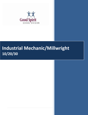
General High-Speed Signal Routingwww.ti.com3General High-Speed Signal Routing3.1Trace ImpedanceFor high speed signals trace impedance needs to designed as to minimize the reflections in traces. Thereare two types of trace impedance that need to be taken into consideration when designing high speedsignals. Single ended impedance is the trace impedance with reference to ground. Differential Impedanceis the impedance between two differential pair signal traces.The High speed protocol that is being designed for determines what the single and differential traceImpedance the traces need to meet as well as the tolerance for the impedance (e.g. 50 Ω 15%). To havedesigns be robust from PCB manufacturing errors and defects design the traces impedance be as close tothe recommended value. The geometry of the traces, the permittivity of the PCB material and the layerssurrounding the trace all impact the impedance of the signal trace.There are many tools available to calculate the trace impedance on high speed traces. Most boardmanufactures will have a preferred tool that PCB designers can use to calculate the Impedance but thereare also many available online.3.2High-Speed Signal Trace LengthsAs with all high-speed signals, keep total trace length for signal pairs to a minimum. Some standards havea maximum trace/ cable length which is specified in the various specifications.3.3High-Speed Signal Trace Length MatchingMatch the etch lengths of the relevant differential pair traces. Intra-pair skew is the term used to define thedifference between the etch length of the and - lane of a differential pair. Inter-pair skew is used todescribe the difference between the etch lengths of a differential pair from another differential pair of thesame group. The etch length of the differential pair groups do not need to match. For example the etchlengths of USB 3.0 TX and RX do not need to match. There are also standards that do not have a Interpair skew requirement because the different lanes do not have to be the same length. When matching theintra-pair skew of the high-speed signals, add serpentine routing to match the lengths as close to themismatched ends as possible Refer to Figure 2.Figure 1. Inter vs. Intra Pair Skew6High-Speed Layout Guidelines for Signal Conditioners and USB HubsCopyright 2018, Texas Instruments IncorporatedSLLA414 – August 2018Submit Documentation Feedback
General High-Speed Signal Routingwww.ti.comFigure 2. Serpentine Trace GeometryUse the above recommendations for the traces serpentine geometry. For example the width of thetrace(W) is 6 mils and the distance between the differential pair(A) is 8 mils. These mean that the width ofthe serpentine(B) is at least 16 mils and the length of C is at least 18 mils.3.4Return PathAn electrical circuit must always be a closed loop system. With DC, the return current takes the way backwith the lowest resistance for DC signals.Figure 3. Return PathAt higher frequencies, the return current flows along the lowest impedance path, this lowest impedancepath is usually the reference plane adjacent to the signal see the figure below. For this reason it is alwaysbest to have a ground plane or power plane on the layer above or below a signal layer. This return pathhelps to reduce impedance changes and decrease EMI issues.SLLA414 – August 2018Submit Documentation FeedbackHigh-Speed Layout Guidelines for Signal Conditioners and USB HubsCopyright 2018, Texas Instruments Incorporated7
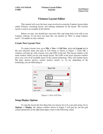
General High-Speed Signal Routingwww.ti.comThe red arrows are the signal path and the blue arrows are the return path.Figure 4. High Frequency Return Path3.5High-Speed Signal Reference PlanesHigh-speed signals should be routed over a solid GND reference plane and not across a plane split or avoid in the reference plane unless absolutely necessary. TI does not recommend high-speed signalreferences to power planes unless it is completely unavoidable.The red arrows are the signal path and the blue arrows are the return path.Figure 5. Routing Across a Split PlaneRouting across a plane split or a void in the reference plane forces return high-frequency current to flowaround the split or void. Figure 5 shows that the return path must take a longer route than the signal paththis can result in the following conditions: Excess radiated emissions from an unbalanced current flow Delays in signal propagation delays due to increased series inductance8High-Speed Layout Guidelines for Signal Conditioners and USB HubsCopyright 2018, Texas Instruments IncorporatedSLLA414 – August 2018Submit Documentation Feedback
General High-Speed Signal Routingwww.ti.com Interference with adjacent signalsDegraded signal integrity (that is, more jitter and reduced signal amplitude)If routing over a plane-split is completely unavoidable, place stitching capacitors across the split to providea return path for the high-frequency current. These stitching capacitors minimize the current loop area andany impedance discontinuity created by crossing the split. These capacitors should be 1 µF or lower andplaced as close as possible to the plane crossing.The red arrows are the signal path and the blue arrows are the return path.Figure 6. AC Capacitor Across a Split PlaneWhen planning a PCB stackup, ensure that planes that do not reference each other are not overlappedbecause this produces unwanted capacitance between the overlapping areas. To see an example of howthis capacitance could pass RF emissions from one plane to the other.It is best to avoid routing across different reference planes because it can cause impedance issues as wellas EMI issue.Do not change the reference plane of the high speed signal trace unless completely unavoidable.SLLA414 – August 2018Submit Documentation FeedbackHigh-Speed Layout Guidelines for Signal Conditioners and USB HubsCopyright 2018, Texas Instruments Incorporated9
General High-Speed Signal Routingwww.ti.comThe red arrows are the signal path and the blue arrows are the return path.Figure 7. Routing Across Different Reference PlanesIf routing across different reference planes cannot be avoided use AC Capacitors to allow the returncurrent to have a pathway.The red arrows are the signal path and the blue arrows are the return path.Figure 8. Routing Across Different Reference Planes with AC CapacitorThe entirety of any high-speed signal trace should maintain the same GND reference from origination totermination. If unable to maintain the same GND reference, via-stitch both GND planes together to ensurecontinuous grounding and uniform impedance. Place these stitching vias symmetrically within 200 mils(center-to-center, closer is better) of the signal transition vias. For an example of stitching vias.10High-Speed Layout Guidelines for Signal Conditioners and USB HubsCopyright 2018, Texas Instruments IncorporatedSLLA414 – August 2018Submit Documentation Feedback
General High-Speed Signal Routingwww.ti.comThe red arrows are the signal path and the blue arrows are the return path.Figure 9. Differential Pair Via Return path Without GND ViasSLLA414 – August 2018Submit Documentation FeedbackHigh-Speed Layout Guidelines for Signal Conditioners and USB HubsCopyright 2018, Texas Instruments Incorporated11
General High-Speed Signal Routingwww.ti.comThe red arrows are the signal path and the blue arrows are the return path.Figure 10. Differential Pair Via Return path With GND Vias12High-Speed Layout Guidelines for Signal Conditioners and USB HubsCopyright 2018, Texas Instruments IncorporatedSLLA414 – August 2018Submit Documentation Feedback
General High-Speed Signal Routingwww.ti.comTI does not recommend high-speed signal references to power planes unless it is completely unavoidable.If it is unavoidable it is best to use AC coupling capacitors and ground vias to allow the return signal tohave a path back from the sink to the source. Figure 11 depicts the use of AC coupling capacitors andground vias for the return path.The red arrows are the signal path and the blue arrows are the return path.Figure 11. VCC Reference PlaneSLLA414 – August 2018Submit Documentation FeedbackHigh-Speed Layout Guidelines for Signal Conditioners and USB HubsCopyright 2018, Texas Instruments Incorporated13
High-Speed Differential Signal Routingwww.ti.com4High-Speed Differential Signal Routing4.1Differential Signal SpacingTo minimize crosstalk in high-speed interface implementations, the spacing between the signal pairs mustbe a minimum of 5 times the width of the trace. This spacing is referred to as the 5W rule. A PCB designwith a calculated trace width of 6 mils requires a minimum of 30 mils spacing between high-speeddifferential pairs. Also, maintain a minimum keep-out area of 30 mils to any other signal throughout thelength of the trace. Where the high-speed differential pairs come adjacent to a clock or a periodic signal,increase this keep-out to a minimum of 50 mils to ensure proper isolation. For examples of high-speeddifferential signal spacing, see Figure 12 and Figure 13.Figure 12. Differential Pair Spacing Next to Other SignalsFigure 13. Differential Pair Spacing Next to Clock or a Periodic SignalIn devices that include multiple high-speed interfaces, avoiding crosstalk between these interfaces isimportant. To avoid crosstalk, ensure that each differential pair is not routed within 30 mils of anotherdifferential pair after package escape and before connector termination.4.2Additional High-Speed Differential Signal Rules 14Do not place probe or test points on any high-speed differential signal.Do not route high-speed traces under or near crystals, oscillators, clock signal generators, switchingpower regulators, mounting holes, magnetic devices, or ICs that use or duplicate clock signals.After BGA breakout, keep high-speed differential signals clear of the SoC because high currenttransients produced during internal state transitions can be difficult to filter out.When possible, route high-speed differential pair signals on the top or bottom layer of the PCB with anadjacent GND layer. TI does not recommend stripline routing of the high-speed differential signals.Ensure that high-speed differential signals are routed 90 mils from the edge of the reference plane.Ensure that high-speed differential signals are routed at least 1.5 W (calculated trace-width 1.5)away from voids in the reference plane. This rule does not apply where SMD pads on high-speeddifferential signals are voided.Maintain constant trace width after the SoC BGA escape to avoid impedance mismatches in thetransmission lines.Maximize differential pair-to-pair spacing when possible.High-Speed Layout Guidelines for Signal Conditioners and USB HubsCopyright 2018, Texas Instruments IncorporatedSLLA414 – August 2018Submit Documentation Feedback
High-Speed Differential Signal Routingwww.ti.com4.3Symmetry in the Differential PairsRoute all high-speed differential pairs together symmetrically and parallel to each other. Deviating fromthis requirement occurs naturally during package escape and when routing to connector pins. Thesedeviations must be as short as possible and package break-out must occur within 0.25 inches of thepackage.Figure 14. Differential Pair SymmetrySLLA414 – August 2018Submit Documentation FeedbackHigh-Speed Layout Guidelines for Signal Conditioners and USB HubsCopyright 2018, Texas Instruments Incorporated15
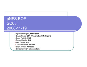
High-Speed Differential Signal Routing4.4www.ti.comConnectors and ReceptaclesWhen implementing a through-hole receptacle (like a USB Standard-A), TI recommends making highspeed differential signal connections to the receptacle on the bottom layer of the PCB. Making theseconnections on the bottom layer of the PCB prevents the through-hole pin from acting as a stub in thetransmission path. For surface-mount receptacles such as USB Micro-B and Micro-AB, make high-speeddifferential signal connections on the top layer. Making these connections on the top layer eliminates theneed for vias in the transmission path. For examples of USB through-hole receptacle connections.(a): Signal coming from the middle of the PCB(b): Signal coming from the top of the PCB(c): Signal Coming from the bottom of the PCBFigure 15. Receptacle Stubs Mitigation16High-Speed Layout Guidelines for Signal Conditioners and USB HubsCopyright 2018, Texas Instruments IncorporatedSLLA414 – August 2018Submit Documentation Feedback
High-Speed Differential Signal Routingwww.ti.com4.5Via Discontinuity MitigationA via presents a short section of change in geometry to a trace and can appear as a capacitive and/or aninductive discontinuity. These discontinuities result in reflections and some degradation of a signal as ittravels through the via. Reduce the overall via stub length to minimize the negative impacts of vias (andassociated via stubs).Because longer via stubs resonate at lower frequencies and increase insertion loss, keep these stubs asshort as possible. In most cases, the stub portion of the via present significantly more signal degradationthan the signal portion of the via. TI recommends keeping via stubs to less than 15 mils. Longer stubsmust be back-drilled. For examples of short and long via lengths, see Figure 16 and Figure 17.Figure 16. Vias With Long StubsSLLA414 – August 2018Submit Documentation FeedbackHigh-Speed Layout Guidelines for Signal Conditioners and USB HubsCopyright 2018, Texas Instruments Incorporated17
High-Speed Differential Signal Routingwww.ti.comFigure 17. Vias With Short Stubs18High-Speed Layout Guidelines for Signal Conditioners and USB HubsCopyright 2018, Texas Instruments IncorporatedSLLA414 – August 2018Submit Documentation Feedback
High-Speed Differential Signal Routingwww.ti.com4.6Back-Drill StubsBack-drilling is a PCB manufacturing process in which the undesired conductive plating in the stub sectionof a via is removed. To back-drill, use a drill bit slightly larger in diameter than the drill bit used to createthe original via hole. When via transitions result in stubs longer than 15 mils, back-drill the resulting stubsto reduce insertion losses and to ensure that they do not resonate.Figure 18. Long Vias With Back-Drilled StubsSLLA414 – August 2018Submit Documentation FeedbackHigh-Speed Layout Guidelines for Signal Conditioners and USB HubsCopyright 2018, Texas Instruments Incorporated19
High-Speed Differential Signal Routing4.7www.ti.comTrace StubsFor high speed signals it is important to minimize stubs on high speed traces to reduce increase insertionloss. Figure 19 depicts a high speed trace with a component on a stub. This stub can be reduced to:Figure 19. Reducing Stub Length4.8Increase Via Anti-Pad DiameterIncreasing the via anti-pad diameter reduces the capacitive effects of the via and the overall insertion loss.Ensure that anti-pad diameter for vias on any high-speed signal are as large as possible (30 mils providessignificant benefits without imposing undue implementation hardship). The copper clearance, indicated bythis anti-pad, must be met on all layers where the via exists, including both routing layer and plane layers.The traces connecting to the via barrel contain the only copper allowed in this area; non-functional orunconnected via pads are not permitted. For an example of a via anti-pad diameter, see the Figure 20.Figure 20. Via Anti-Pad20High-Speed Layout Guidelines for Signal Conditioners and USB HubsCopyright 2018, Texas Instruments IncorporatedSLLA414 – August 2018Submit Documentation Feedback
High-Speed Differential Signal Routingwww.ti.com4.9Equalize Via CountIf using vias is necessary on a high-speed differential signal trace, ensure that the via count on eachmember of the differential pair is equal and that the vias are as equally spaced as possible. It is importantto make sure that the different lanes that lengths need to match have the same amount of vias on thelines. Also designers should take into account the length of the vias when verifying parameters such asinter pair skew.4.10 Surface-Mount Device Pad Discontinuity MitigationAvoid including surface-mount devices (SMDs) on high-speed signal traces because these devicesintroduce discontinuities that can negatively affect signal quality. When SMDs are required on the signaltraces (for example, the USB SuperSpeed transmit AC coupling capacitors) the maximum permittedcomponent size is 0603. TI strongly recommends using 0402 or smaller. Place these componentssymmetrically during the layout process to ensure optimum signal quality and to minimize reflection. Forexamples of correct and incorrect AC coupling capacitor placement.Figure 21. AC-Coupling Capacitor PlacementSLLA414 – August 2018Submit Documentation FeedbackHigh-Speed Layout Guidelines for Signal Conditioners and USB HubsCopyright 2018, Texas Instruments Incorporated21
High-Speed Differential Signal Routingwww.ti.comTo minimize the discontinuities associated with the placement of these components on the differentialsignal traces, TI recommends voiding the SMD mounting pads of the reference plane by 100%. This voidshould be at least two PCB layers deep. For an example of a reference plane voiding of surface mountdevices, see Figure 22.Figure 22. Void Below Surface Mount DevicesAlso to minimize the inductance of the AC coupling capacitors it is best to use 0201 capacitor sizes.4.11 Signal BendingAvoid the introduction of bends into high-speed differential signals. When bending is required, maintain abend angle greater than 135 to ensure that the bend is as loose as a possible. For an example of highspeed signal bending rules see Figure 23.Figure 23. Signal Bending Rules22High-Speed Layout Guidelines for Signal Conditioners and USB HubsCopyright 2018, Texas Instruments IncorporatedSLLA414 – August 2018Submit Documentation Feedback
High-Speed Differential Signal Routingwww.ti.com4.12 Suggested PCB StackupsTI recommends a PCB of at least six layers for PCBs with high speed signals. The following tablesprovides example PCB stackups.Table 2. Possible Board Stack-up on a Six-Layer PCBModel 1Model 2Model 3Model 4Model 5Model 6Model 7Layer 1SIGNALSIGNALSIGNALGROUNDSIGNALSIGNALSIGNALLayer 2GROUNDSIGNALGROUNDPOWERGROUNDGROUNDGROUNDLayer 3SIGNALPOWERPOWERSIGNALPOWERPOWERPOWERLayer 4SIGNALGROUNDPOWERSIGNALSIGNALGROUNDGROUNDLayer 5POWERSIGNALGROUNDPOWERGROUNDNOT USEDSIGNALLayer oodBadSignal IntegrityIf four layer PCBs are required the following table provides example PCB stackups.Table 3. Possible Board Stack-up on a Four-Layer PCBModel 1Model 2Model 3Model 4Layer 1SIGNALSIGNALSIGNALGROUNDLayer 2SIGNALGROUNDGROUNDSIGNALLayer 3POWERPOWERSIGNALPOWERLayer CBadBadBadBadSignal IntegrityBadBadGoodBadFor more than 6 PCB Layers Stack-ups use the following examples.Table 4. Other Example PCB GNALSIGNAL (1)SIGNALSIGNAL (1)POWER/GROUND (2)POWERSIGNALPOWER/GROUND (2)GROUNDSIGNAL (1)SIGNALSIGNAL (1)GROUNDSIGNAL(1)(2)Route directly adjacent signal layers at a 90 offset to each otherPlane may be split depending on specific board considerations. Ensure that traces on adjacent planes do not cross splits.SLLA414 – August 2018Submit Documentation FeedbackHigh-Speed Layout Guidelines for Signal Conditioners and USB HubsCopyright 2018, Texas Instruments Incorporated23
High-Speed Differential Signal Routingwww.ti.com4.13 ESD/EMI ConsiderationsWhen choosing ESD/EMI components, TI recommends selecting devices that permit flow-through routingof the USB differential signal pair because they provide the cleanest routing. For example, the TITPD4EUSB30 can be combined with the TI TPD2EUSB30 to provide flow-through ESD protection for bothUSB2 and USB3 differential signals without the need for bends in the signal pairs.4.14 ESD/EMI Layout Rules 5References 24Place ESD and EMI protection devices as close as possible to the connector.Keep any unprotected traces away from protected traces to minimize EMI coupling.Incorporate 60% voids under the ESD/EMI component signal pads to reduce losses.Use 0402 0-Ω resistors for common-mode filter (CMF) no-stuff options because larger components willtypically introduce more loss that the CMF itself.Place any required signal pair AC coupling capacitors on the protected side of the CMF and as closeas possible to the CMF.If vias are needed to transition to the CMF layer, ensure that the vias are as close as possible to theCMF.Keep the overall routing of AC coupling capacitors CMF ESD protection as short and as close aspossibl
The red arrows are the signal path and the blue arrows are the return path. Figure 5. Routing Across a Split Plane Routing across a plane split or a void in the reference plane forces return high-frequency current to flow around the split or void. Figure 5 shows that the return path must take a longer route than the signal path