Transcription
BD LSRFortessaCell AnalyzerUser’s GuideFor Research Use Onlybdbiosciences.com23-11093-00 Rev. A3/2010Becton, Dickinson and CompanyBD BiosciencesBD BiosciencesEuropean Customer SupportSan Jose, CA 95131Tel 877.232.8995Fax 800.325.9637ResearchApplications@bd.comTel 32.2.400.98.95Fax 32.2.401.70.94help.biosciences@europe.bd.com
Copyrights 2010, Becton, Dickinson and Company. All rights reserved. No part of this publication may be reproduced,transmitted, transcribed, stored in retrieval systems, or translated into any language or computer language, inany form or by any means: electronic, mechanical, magnetic, optical, chemical, manual, or otherwise, withoutprior written permission from BD Biosciences.The information in this guide is subject to change without notice. BD Biosciences reserves the right to changeits products and services at any time to incorporate the latest technological developments. Although this guidehas been prepared with every precaution to ensure accuracy, BD Biosciences assumes no liability for any errorsor omissions, nor for any damages resulting from the application or use of this information. BD Bioscienceswelcomes customer input on corrections and suggestions for improvement.TrademarksClorox is a registered trademark of The Clorox Company. SPHERO is a trademark of Spherotech, Inc. ModfitLT is a trademark of Verity Software House, Inc. Microsoft and Windows are registered trademarks ofMicrosoft Corporation. Texas Red and Alexa Fluor are registered trademarks, and Pacific Blue is atrademark, of Molecular Probes, Inc. Teflon is a registered trademark of E.I. du Pont de Nemours andCompany.Cy is a trademark of Amersham Biosciences Corp. Cy dyes are subject to proprietary rights of AmershamBiosciences Corp and Carnegie Mellon University and are made and sold under license from AmershamBiosciences Corp only for research and in vitro diagnostic use. Any other use requires a commercial sublicensefrom Amersham Biosciences Corp, 800 Centennial Avenue, Piscataway, NJ 08855-1327, USA.BD, BD Logo and all other trademarks are property of Becton, Dickinson and Company. 2010 BDPatentsThe BD LSRFortessa Cell Analyzer is covered by one or more of the following US Patents and foreignequivalents: 7,129,505; 6,944,338; 6,809,804; 6,683,314; 6,014,904APC-Cy7: US 5,714,386BD FACS lysing solution: US 4,654,312; 4,902,613; 5,098,849Regulatory informationFor Research Use Only. Not for use in diagnostic or therapeutic procedures.Class I (1) Laser Product
FCC informationWARNING: Changes or modifications to this unit not expressly approved by the party responsible forcompliance could void the user’s authority to operate the equipment.NOTICE: This equipment has been tested and found to comply with the limits for a Class A digital device,pursuant to Part 15 of the FCC Rules. These limits are designed to provide reasonable protection againstharmful interference when the equipment is operated in a commercial environment. This equipment generates,uses, and can radiate radio frequency energy and, if not installed and used in accordance with the instructionmanual, may cause harmful interference to radio communications. Operation of this equipment in aresidential area is likely to cause harmful interference in which case the user will be required to correct theinterference at his or her own expense. Shielded cables must be used with this unit to ensure compliance withthe Class A FCC limits. This Class A digital apparatus meets all requirements of the Canadian InterferenceCausing Equipment Regulations. Cet appareil numérique de la classe A respecte toutes les exigences duRéglement sur le matériel brouilleur du Canada.Compliance informationNOTICE: This laboratory equipment has been tested and found to comply with the EMC and the LowVoltage Directives. This includes FCC, Part 15 compliance for a Class A Digital Device.CAUTION: Any unauthorized modifications to this laboratory equipment may affect the RegulatoryCompliance items stated above.HistoryRevisionDateChange made647247 Rev. A5/2009New document23-11093-00 Rev. A3/2010Updated
ContentsChapter 1: About this guide1What this guide covers . . . . . . . . . . . . . . . . . . . . . . . . . . . . . . . . . . . . . . . . . . . . . 2Conventions used in this guide . . . . . . . . . . . . . . . . . . . . . . . . . . . . . . . . . . . . . . . 3About the BD LSRFortessa documentation . . . . . . . . . . . . . . . . . . . . . . . . . . . . . . 5Technical assistance . . . . . . . . . . . . . . . . . . . . . . . . . . . . . . . . . . . . . . . . . . . . . . . 7Chapter 2: Introduction9Instrument overview . . . . . . . . . . . . . . . . . . . . . . . . . . . . . . . . . . . . . . . . . . . . . . 10Components . . . . . . . . . . . . . . . . . . . . . . . . . . . . . . . . . . . . . . . . . . . . . . . . . . . . 11Fluidics . . . . . . . . . . . . . . . . . . . . . . . . . . . . . . . . . . . . . . . . . . . . . . . . . . . . . . . . 13Sheath and waste containers . . . . . . . . . . . . . . . . . . . . . . . . . . . . . . . . . . . . . . . . 17Optics . . . . . . . . . . . . . . . . . . . . . . . . . . . . . . . . . . . . . . . . . . . . . . . . . . . . . . . . . 18Workstation . . . . . . . . . . . . . . . . . . . . . . . . . . . . . . . . . . . . . . . . . . . . . . . . . . . . 21Chapter 3: Cytometer setup23Starting the cytometer and computer . . . . . . . . . . . . . . . . . . . . . . . . . . . . . . . . . 24Preparing the sheath container . . . . . . . . . . . . . . . . . . . . . . . . . . . . . . . . . . . . . . 26Removing air bubbles . . . . . . . . . . . . . . . . . . . . . . . . . . . . . . . . . . . . . . . . . . . . . 28Preparing the waste container . . . . . . . . . . . . . . . . . . . . . . . . . . . . . . . . . . . . . . . 30Priming the fluidics . . . . . . . . . . . . . . . . . . . . . . . . . . . . . . . . . . . . . . . . . . . . . . . 33About the optical filters and mirrors . . . . . . . . . . . . . . . . . . . . . . . . . . . . . . . . . . 34Changing optical filters and mirrors . . . . . . . . . . . . . . . . . . . . . . . . . . . . . . . . . . 36Custom configurations and baselines . . . . . . . . . . . . . . . . . . . . . . . . . . . . . . . . . 37
viBD LSRFortessa Cell Analyzer User’s GuideChapter 4: Maintenance39Maintenance overview . . . . . . . . . . . . . . . . . . . . . . . . . . . . . . . . . . . . . . . . . . . . 40Cleaning the fluidics . . . . . . . . . . . . . . . . . . . . . . . . . . . . . . . . . . . . . . . . . . . . . . 41Shutting down the cytometer . . . . . . . . . . . . . . . . . . . . . . . . . . . . . . . . . . . . . . . . 43Flushing the system . . . . . . . . . . . . . . . . . . . . . . . . . . . . . . . . . . . . . . . . . . . . . . . 44Maintaining the waste management system . . . . . . . . . . . . . . . . . . . . . . . . . . . . . 46Replacing the waste air filter . . . . . . . . . . . . . . . . . . . . . . . . . . . . . . . . . . . . . . . . 49Changing the sheath filter . . . . . . . . . . . . . . . . . . . . . . . . . . . . . . . . . . . . . . . . . . 50Changing the Bal seal . . . . . . . . . . . . . . . . . . . . . . . . . . . . . . . . . . . . . . . . . . . . . 52Changing the sample tube O-ring . . . . . . . . . . . . . . . . . . . . . . . . . . . . . . . . . . . . 54Chapter 5: Optimizing cytometer settings57Cytometer settings workflow . . . . . . . . . . . . . . . . . . . . . . . . . . . . . . . . . . . . . . . 58Verifying the configuration and user preferences . . . . . . . . . . . . . . . . . . . . . . . . . 61Running a performance check . . . . . . . . . . . . . . . . . . . . . . . . . . . . . . . . . . . . . . . 64Setting up an experiment . . . . . . . . . . . . . . . . . . . . . . . . . . . . . . . . . . . . . . . . . . . 69Creating application settings . . . . . . . . . . . . . . . . . . . . . . . . . . . . . . . . . . . . . . . . 73Recording compensation controls . . . . . . . . . . . . . . . . . . . . . . . . . . . . . . . . . . . . 76Calculating compensation . . . . . . . . . . . . . . . . . . . . . . . . . . . . . . . . . . . . . . . . . . 80Chapter 6: Recording and analyzing data81Data recording and analysis workflow . . . . . . . . . . . . . . . . . . . . . . . . . . . . . . . . 82Preparing the workspace . . . . . . . . . . . . . . . . . . . . . . . . . . . . . . . . . . . . . . . . . . . 83Recording data . . . . . . . . . . . . . . . . . . . . . . . . . . . . . . . . . . . . . . . . . . . . . . . . . . 85Analyzing data . . . . . . . . . . . . . . . . . . . . . . . . . . . . . . . . . . . . . . . . . . . . . . . . . . 88Reusing an analysis . . . . . . . . . . . . . . . . . . . . . . . . . . . . . . . . . . . . . . . . . . . . . . . 94Chapter 7: Technical overview97About fluidics . . . . . . . . . . . . . . . . . . . . . . . . . . . . . . . . . . . . . . . . . . . . . . . . . . . 98About optics . . . . . . . . . . . . . . . . . . . . . . . . . . . . . . . . . . . . . . . . . . . . . . . . . . . 100About electronics . . . . . . . . . . . . . . . . . . . . . . . . . . . . . . . . . . . . . . . . . . . . . . . 111
ContentsChapter 8: Troubleshooting115Cytometer troubleshooting . . . . . . . . . . . . . . . . . . . . . . . . . . . . . . . . . . . . . . . . 116Electronics troubleshooting . . . . . . . . . . . . . . . . . . . . . . . . . . . . . . . . . . . . . . . . 127Chapter 9: Detector array configurations129Fluorescence spectra . . . . . . . . . . . . . . . . . . . . . . . . . . . . . . . . . . . . . . . . . . . . . 130About configuration maps . . . . . . . . . . . . . . . . . . . . . . . . . . . . . . . . . . . . . . . . 132About the base configuration . . . . . . . . . . . . . . . . . . . . . . . . . . . . . . . . . . . . . . 133Base configuration octagon and trigon maps . . . . . . . . . . . . . . . . . . . . . . . . . . 138Special Order configurations . . . . . . . . . . . . . . . . . . . . . . . . . . . . . . . . . . . . . . . 149Chapter 10: Manual settings163About laser delay . . . . . . . . . . . . . . . . . . . . . . . . . . . . . . . . . . . . . . . . . . . . . . . 164Optimizing laser delay . . . . . . . . . . . . . . . . . . . . . . . . . . . . . . . . . . . . . . . . . . . 165Adjusting area scaling . . . . . . . . . . . . . . . . . . . . . . . . . . . . . . . . . . . . . . . . . . . . 168Chapter 11: Supplies and consumables175Ordering information . . . . . . . . . . . . . . . . . . . . . . . . . . . . . . . . . . . . . . . . . . . . 176Particles . . . . . . . . . . . . . . . . . . . . . . . . . . . . . . . . . . . . . . . . . . . . . . . . . . . . . . 177Reagents . . . . . . . . . . . . . . . . . . . . . . . . . . . . . . . . . . . . . . . . . . . . . . . . . . . . . . 178Equipment . . . . . . . . . . . . . . . . . . . . . . . . . . . . . . . . . . . . . . . . . . . . . . . . . . . . 179Index181vii
1About this guideThis section includes these topics:zWhat this guide covers (page 2)zConventions used in this guide (page 3)zAbout the BD LSRFortessa documentation (page 5)zTechnical assistance (page 7)
2BD LSRFortessa Cell Analyzer User’s GuideWhat this guide coversThis guide describes the procedures necessary to operate andmaintain your BD LSRFortessa cell analyzer. Becausemany cytometer functions are controlled by BD FACSDiva software, this guide also contains information aboutsoftware features required for basic cytometer setup andoperation.This guide assumes you have a working knowledge of basicMicrosoft Windows operation. If you are not familiarwith the Windows operating system, see the documentationprovided with your computer.
Chapter 1: About this guideConventions used in this guideAbout this topicThis topic describes the conventions used throughout thisguide.Safety symbolsThese safety symbols are used in this guide and on safetylabels to alert you to potential hazards.SymbolMeaningCaution alertIdentifies a hazard or unsafe practice that couldresult in data loss, material damage, minor injury,severe injury, or deathBiological hazardElectrical hazardLaser hazardHot surface; High temperatures; Burn hazard3
4BD LSRFortessa Cell Analyzer User’s GuideText and keyboardconventionsConventionUseNotesA note describes important features orinstructions.BoldBold is used to indicate software elementssuch as dialogs, fields, and buttons.ItalicsItalics are used to highlight book titles.Italics are also used in describing softwareto indicate specific text typed into awindow or dialog. The arrow is used to indicate menuselection paths. For example, “SelectFile Print” means to select the Printoption from the File menu.Ctrl XWhen used with key names, a plus sign ( )means to press two keys simultaneously.For example, Ctrl P means to hold downthe Control key while pressing the p key.
Chapter 1: About this guideAbout the BD LSRFortessa documentationAbout this topicThis topic describes the documentation available with theBD LSRFortessa flow cytometer.Publication formatsThis guide is provided in PDF format to provide aneco-friendly option. All content is also included in theBD FACSDiva software Help.Online helpThe online help installed with BD FACSDiva softwareincludes all content from this guide and the documents listedbelow. Access BD LSRFortessa online help from the Helpmenu in BD FACSDiva software.The online help is compiled from the following documents:zBD FACSDiva Software Reference Manual: Includesinstructions or descriptions for installation and setup,workspace components, acquisition controls, analysistools, and data management. Access this manual fromthe BD FACSDiva Software Help menu (Help Literature Reference Manual), or by double-clickingthe shortcut on the desktop.zBD Cytometer Setup and Tracking Application Guide:Describes how to use the Cytometer Setup and Trackingfeatures in BD FACSDiva software.zBD LSRFortessa Cell Analyzer Site Preparation Guide:Contains specifications for:– Cytometer weight and size– Temperature and other environmental requirements– Electrical requirements5
6BD LSRFortessa Cell Analyzer User’s GuidezBD High Throughput Sampler User’s Guide: Describeshow to set up and operate the BD High ThroughputSampler (HTS) option. It also contains a description ofBD FACSDiva software features specific to the HTS.zBD FACSFlow Supply System User’s Guide: Describesthe optional automated sheath and waste fluid controlsystem designed for use with the BD LSR II andBD LSRFortessa.
Chapter 1: About this guideTechnical assistanceAbout this topicThis topic describes how to get technical assistance.Getting assistance fromthis guideFor technical questions or assistance in solving a problem:Contacting technicalsupportzRead the sections of the documentation specific to theoperation you are performing. See About theBD LSRFortessa documentation (page 5) for moreinformation.zSee Troubleshooting (page 115).If additional assistance is required, contact your localBD Biosciences customer support representative or supplier.When contacting BD Biosciences, have the followinginformation available:zProduct name, part number, and serial numberzVersion of BD FACSDiva software you are usingzAny error messageszDetails of recent system performanceFor cytometer support from within the US, call877.232.8995.For support from within Canada, call 888.259.0187.Customers outside the US and Canada, contact your localBD representative or distributor.7
Need more information fast?Information about this product is also available in yoursoftware's Help system.You can keep the Help window open while you use thesoftware or print the information directly from the window.Internet access is not required to use the Help system.
2IntroductionThe following topics are covered in this section:zInstrument overview (page 10)zComponents (page 11)zFluidics (page 13)zSheath and waste containers (page 17)zOptics (page 18)zWorkstation (page 21)
10BD LSRFortessa Cell Analyzer User’s GuideInstrument overviewThe BD LSRFortessa is an air-cooled multi-laser benchtopflow cytometer with the ability to acquire parameters for alarge number of colors. It uses fixed-alignment lasers thattransmit light through a flow cell to configurable octagonand trigon detector arrays. These detectors collect andtranslate the resulting fluorescence signals into electronicsignals. Cytometer electronics convert these signals intodigital data.
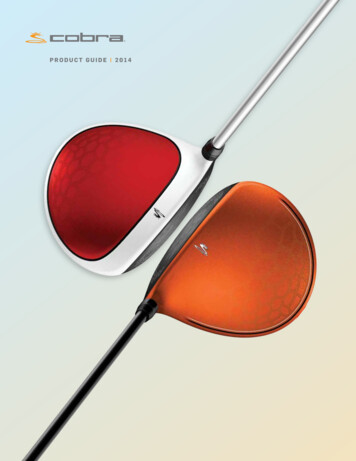
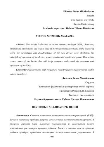
Chapter 2: IntroductionComponentsAbout this topicThis topic describes the instrument’s components.Instrument overviewHeat ventilation slotsPower switch (right side)Sample injection port (SIP)fluidicsinterconnectsFront doors (trigon detectorarrays)Side drawer (octagon or trigondetector arrays)Control panelCaution! Do not place any objects on top of the instrument.Blocking the ventilation may cause the instrument tooverheat.Caution: Electrical Hazard! Do not place liquids on top of theinstrument. Any spill of liquid into the ventilation openingscould cause electrical shock or damage to the instrument.11
12BD LSRFortessa Cell Analyzer User’s GuidePower switchThe power switch is located on the right side of theinstrument.Control panelThe control panel contains the following fluidics controls:zSample flow rate control buttonszFluid control buttonszSample fine adjust knobSample flow rate control buttonsRelated topicszFluidics (page 13)zOptics (page 18)Fluid control buttons
Chapter 2: IntroductionFluidicsAbout this topicThis topic describes the fluidics system.PurposeThe purpose of the fluidics system is to carry the sample outof the sample tube and into the sensing region of the flowcell. Cells are carried in the sample core stream in single fileand measured individually.Sample flow rate controlThree flow rate control buttons (LO, MED, and HI) set thesample flow rate through the flow cell. The SAMPLE FINEADJ knob allows you to adjust the rate to intermediatelevels.When the SAMPLE FINE ADJ knob is at its midpoint, thesample flow rates at the LO, MED, and HI settings areapproximately 12, 35, and 60 µL/min of sample, respectively.The knob turns five full revolutions in either direction fromits midpoint, providing sample flow rates from 0.5–2X themidpoint value. For example, if the LO button is pressed, theknob will give flow rates from approximately 6–24 µL/min.13
14BD LSRFortessa Cell Analyzer User’s GuideFluid controlThree fluid control buttons (RUN, STNDBY, and PRIME)set the cytometer mode.zRUN. Pressurizes the sample tube to transport thesample through the sample injection tube and into theflow cell.The RUN button is green when the sample tube is onand the support arm is centered. When the tube supportarm is moved left or right to remove a sample tube, thecytometer switches to an automatic standby status toconserve sheath fluid, and the RUN button changes toorange.zSTNDBY (standby). Stops fluid flow to conserve sheathfluid.When you leave the cytometer for more than a fewminutes, place a tube containing 1 mL of deionized (DI)water on the sample injection port (SIP) and pressSTNDBY.zPRIME. Prepares the fluidics system by draining andfilling the flow cell with sheath fluid.The fluid flow initially stops and pressure is reversed toforce fluid out of the flow cell and into the wastecontainer. After a preset time, the flow cell fills withsheath fluid at a controlled rate to prevent bubbleformation or entrapment. At completion, the cytometerswitches to standby mode.
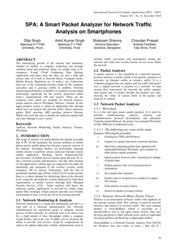
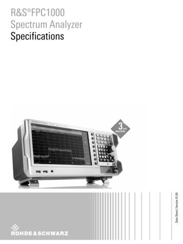
Chapter 2: IntroductionSample injection portThe SIP is where the sample tube is installed. The SIPincludes the sample injection tube and the tube support arm.Samples are introduced through a stainless steel injectiontube equipped with an outer droplet containment sleeve. Thesleeve works in conjunction with a vacuum pump toeliminate droplet formation of sheath fluid as it backflushesfrom the sample injection tube.Outer sleeveSample injection tubeTube support armzSample injection tube. Stainless steel tube that carriessample from the sample tube to the flow cell. This tube iscovered with an outer sleeve that serves as part of thedroplet containment system.zTube support arm. Arm that supports the sample tubeand activates the droplet containment system vacuum.The vacuum is on when the arm is positioned to the sideand off when the arm is centered.Note: If a sample tube is left on the SIP with the tubesupport arm to the side (vacuum on), the sample will beaspirated into the waste container.15
16BD LSRFortessa Cell Analyzer User’s GuideCautions when using theHTS optionCaution: Biohazard! When using the BD LSRFortessacytometer with the BD High Throughput Sampler (HTS),ensure that the HTS is completely pushed into the operatingposition before removing the DCM (droplet containmentmodule) sleeve or disconnecting the sample coupler from theSIP. This is to avoid accidental leakage of potentiallybiohazardous liquids directly onto the instrument. With theHTS in the proper location, the containment dish withpadding is directly below the SIP.Caution! If you are using the HTS option, always slide theHTS mount slowly to prevent sample cross-contaminationwhen the wells are full. Never move the HTS when it is inoperation.Caution! Do not lean on or put any weight on the HTS as itcould damage the instrument.Droplet containmentmoduleThe DCM prevents sheath fluid from dripping from the SIPand provides biohazard protection.When no sample tube is installed on the SIP, sheath fluidbackflushes through the sample injection tube. Thisbackflush helps prevent carryover of cells between samples.The DCM vacuum is activated when the sample tube isremoved and the tube support arm is moved to the side.Sheath fluid is aspirated as it backflushes the sampleinjection tube.
Chapter 2: IntroductionSheath and waste containersAbout this topicThis topic describes the sheath and waste containers. Thesheath and waste containers are outside the cytometer andare positioned on the floor.Note: If your system is using the BD FACSFlow supplysystem, please see the documentation provided with yoursystem.Sheath containerThe sheath container has a capacity of 8 L. Sheath fluid isfiltered through an in-line, interchangeable filter thatprevents small particles from entering the sheath fluid lines.Caution! Do not fill the sheath tank to its maximumcapacity (8 L). When an overfull tank is pressurized, erraticcytometer performance can result.Waste containerThe waste container has a capacity of 10 L. An alarm soundswhen the container becomes full.Related topicszPreparing the sheath container (page 26)zPreparing the waste container (page 30)17
18BD LSRFortessa Cell Analyzer User’s GuideOpticsAbout this topicDetector arraysThis topic describes the optical components for theBD LSRFortessa cytometer including:zDetector arrayszLaser optionszOptical filterszSignal detectorsThe BD LSRFortessa detector arrays consist of:zOctagons. Array of PMTs and filters that can detect upto eight signals.zTrigons. Array of PMTs and filters that can detect up tothree signals.sLocked cover (lasersaccessible by BD Service only)Front door panels (trigons)Side drawer (octagons or trigons)
Chapter 2: IntroductionLaser optionsOptical filtersThe BD LSRFortessa flow cytometer can be configured withup to four lasers listed in the following table. The cytometercan also be upgraded with lasers from this list, or configuredwith up to five lasers from a variety of wavelengths throughour Special Order Research Program.LaserWavelength (nm)Power (mW)Blue48850Red64040Violet40550UV35520Optical filters attenuate light or help direct it to theappropriate detectors. The name and spectral characteristicsof each filter appear on its holder.There are two types of optical filters in the BD LSRFortessa:zLongpass dichroic filters (LPs). Transmit wavelengthsthat are longer than the specified value and reflect alllight below the specified wavelength.zBandpass filters (BPs). Pass a narrow spectral band oflight.When dichroic filters are used as steering optics to directdifferent color light signals to different detectors, they arecalled dichroic mirrors. LP dichroic mirrors transmit longerwavelengths to one detector while reflecting shorterwavelengths to a different detector.19
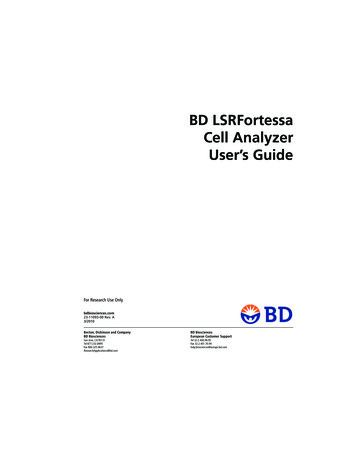
BD LSRFortessa Cell Analyzer User’s GuideThe BD LSRFortessa cytometer octagon and trigon detectorarrays use dichroic longpass mirrors on their inner rings, andbandpass filters on their outer rings. You can customize thearrays with other wavelengths of filters and mirrors.BDBandpass filtersGFLongpass dichroicmirrorsHEAC20Signal detectorsLight signals are generated as particles pass through the laserbeam in a fluid stream. When these optical signals reach adetector, electrical pulses are created that are then processedby the electronics system.There are two types of signal detectors in theBD LSRFortessa flow cytometer:zPhotomultiplier tubes (PMTs). Used to detect theweaker signals generated by side scatter and allfluorescence channels. These signals are amplified byapplying a voltage to the PMTs.zPhotodiodes. Less sensitive to light signals than thePMTs. A photodiode is used to detect the strongerforward scatter (FSC) signal. However, an optional PMT
Chapter 2: Introductionfor detecting FSC is available through the BD SpecialOrder Research Program.Related topicszOptical filter theory (page 103)zAbout the base configuration (page 133)zSpecial Order configurations (page 149)WorkstationAbout this topicThis topic describes the components of the BD LSRFortessaworkstation.Workstation componentsAcquisition, analysis, and most instrument functions arecontrolled by the BD LSRFortessa workstation. It includes aPC, one or two monitors, and a printer.Your workstation is equipped with the following:Related topicszMicrosoft Windows operating systemzBD FACSDiva software version 6.2 or later for dataacquisition and analysiszSoftware documentation including an online help systemzAbout the BD LSRFortessa documentation (page 5)21
Need more information fast?Information about this product is also available in yoursoftware's Help system.You can keep the Help window open while you use thesoftware or print the information directly from the window.Internet access is not required to use the Help system.
3Cytometer setupThis section includes the following topics:zStarting the cytometer and computer (page 24)zPreparing the sheath container (page 26)zRemoving air bubbles (page 28)zPreparing the waste container (page 30)zPriming the fluidics (page 33)zAbout the optical filters and mirrors (page 34)zChanging optical filters and mirrors (page 36)zCustom configurations and baselines (page 37)
24BD LSRFortessa Cell Analyzer User’s GuideStarting the cytometer and computerAbout this topicThis topic describes how to start the cytometer and turn onthe computer.ProcedureTo start the cytometer:1. Turn on the power to the flow cytometer.Note: If your system is using the BD FACSFlow supplysystem, make sure that the BD FACSFlow supply systemis powered on before the cytometer.2. Allow 30 minutes for the optical system temperature tostabilize.Caution! Failure to warm up and stabilize theinstrument could affect sample data.3. Turn on the computer and log in to Windows.Note: You can turn on the power to the flow cytometerand the workstation in any order.4. Start BD FACSDiva software by double-clicking theshortcut on the desktop, and log in to the software.
Chapter 3: Cytometer setup5. Check the Cytometer window in BD FACSDiva softwareto ensure that the cytometer is connected to theworkstation.The cytometer connects automatically. While connecting,the message Cytometer Connecting is displayed in thestatus area of the Cytometer window. When connectioncompletes, the message changes to CytometerConnected.If the message Cytometer Disconnected appears, seeElectronics troubleshooting (page 127).25
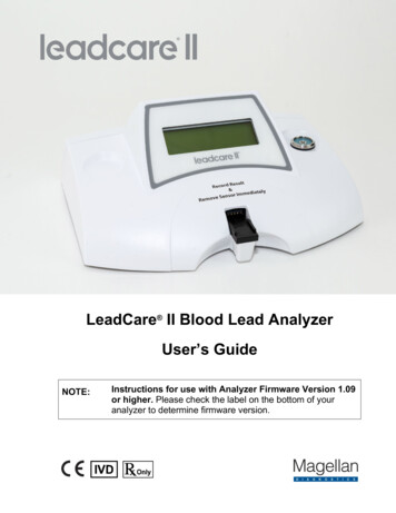
26BD LSRFortessa Cell Analyzer User’s GuidePreparing the sheath containerAbout this topicThis topic describes how to prepare the sheath container.Note: If your system is using the BD FACSFlow supplysystem, please see the documentation provided with yoursystem.When to check the sheath Check the fluid levels in the sheath container every time youcontaineruse the cytometer. This ensures that you do not run out ofsheath fluid during an experiment.Sheath containercomponentsClamp knobCap handleAir line (green)Tank handleVent valveSheath fluid line (blue)(to cytometer)Filter assembly
Chapter 3: Cytometer setupProcedureTo prepare the sheath container:1. Verify that the flow cytometer is in standby mode.Press the STNDBY button on the control panel ifnecessary.2. Disconnect the air line (green) from the sheath container.3. Depressurize the sheath container by pulling up on thevent valve.4. Remove the sheath container lid.Unscrew the clamp knob and push down to loosen, ifnecessary. Tilt the cap to the side to remove it from thetank.5. Add 6 L of sheath fluid, such as BD FACSFlow solution,to the sheath container.Caution! Do not fill the sheath tank to its maximumcapacity (8 L). When an overfull tank is pressurized,erratic cytometer performance can result.6. Replace the sheath container lid.7. Reconnect the air line (green).8. Make sure the gasket on the inside lip of the sheath lid isseated correctly and has not slipped out of position.If the gasket is not seated correctly, the tank will notpressurize properly.9. Close the sheath lid and tighten the clamp knob tofinger-tight. Ensure that the sheath fluid line (blue) is notkinked.27
28BD LSRFortessa Cell Analyzer User’s GuideRelated topicszRemoving air bubbles (page 28)zChanging the sheath filter (page 50)Removing air bubblesAbout this topicThis topic describes how to remove trapped air bubbles inthe sheath filter and the sheath line. Air bubbles canoccasionally dislodge and pass through the flow cell,resulting in inaccurate data.ProcedureTo remove air bubbles:1. Check the sheath filter for trapped air bubbles.Cytometer fluid line(roller clamp not visible)Vent fittingVent line
Chapter 3: Cytometer setup2. If bubbles are vi
BD LSRFortessa flow cytometer. Publication formats This guide is provided in PDF format to provide an eco-friendly option. All content is also included in the BD FACSDiva software Help. Online help The online help installed with BD FACSDiva software includes all content from this guide and the documents listed below.