Transcription
STATE-OF-THE-ART REPORTFull Depth Precastand Precast, PrestressedConcrete Bridge Deck PanelsMohsen A. lssa, Ph.D., P.E.Associate Professorof Civil EngineeringDepartment of Civil andMaterials EngineeringUniversity of Illinois at ChicagoChicago , IllinoisAhmad-TalalldrissResearch AssistantDepartment of Civil andMaterials EngineeringUniversity of Illinois at ChicagoChicago , Illinoislraj I. Kaspar, P.E.Engineer of Bridge DesignIllinois Departmentof TransportationBureau of Bridges and StructuresSpringfield , IllinoisSince 1970, there has been a dramaticincrease in the use of full depth precast andprecast, prestressed concrete deck panelsfor the rehabilitation and new construction ofbridges. In order to document the variousapplications of bridge deck panels in NorthAmerica, a questionnaire survey was sent tothe departments of transportation (DOTs)of individual states and one province.Requested information in the survey includedtype of construction, deck dimensions, decksupporting system, panel dimensions andreinforcement, type of connecting systembetween panels and supporting system, typeof joint between the adjacent panels, type ofbonding material used to fill the joints,problems associated with the joints, reasonsfor adverse results, and type of protectionsystem. The returned questionnaires werecompiled and analyzed. This paper summarizes the significant results of this survey.he dramatic increase in the rehabilitation of existingsteel or concrete girder bridges on major highwayswith high traffic volumes has foc used attention onthe use of precast concrete deck panels to shorten the timeof reconstruction and reduce the time of bridge closures. Inselecting a bridge deck rehabilitation system, the followi ngcriteria must be adequately addressed:1. Strength and serviceability2. Performance and durability3. Rapid construction4. Minimum interference with traffic5. Minimum maintenance requirementsTSalah Y. Khayyat, P.E.Bridge Standard andSpecifications EngineerIllinois Departmentof TransportationBureau of Bridges and StructuresSpringfield, IllinoisJanuary-February 199559
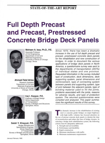
Fig. 2. Transverse joint betweenprecast panels during construction.Fig. 1. View of system under construction.Table 1. Departments of transportation (DOTs) response summary.Number of surveys mailed out to DOTs53Number of DOTs responding by mailNumber of DOTs responding by telephone38Total number of DOTs responding51Number of DOTs reporting using this system1313-38Number of DOTs reporting not using this syste m- Number of DOTs interested in using this system43Number of DOTs not interested in using this system8-Table 2. Type of construction.Type of constructionDepartment ofTransportationNumber ---Indiana2 Washington 5California1-5I.· Precast,prestressed panelsPrecast panels./RehabilitationNewDecember 1991October 1992-May 1987October J987--./ Iowa./J-5r------Spring 1992Fall 1992-HiConnecticutJ-5-./1990-Maryland2-./1983-New York12././Ohio1-5./-Illinois2Ontario, Canada1-5./-TexasI./-Virginia2./-1985-I1972, 1991- 60----./"" 1986-1986, 1987-1990-1985---PC! JOURNAL
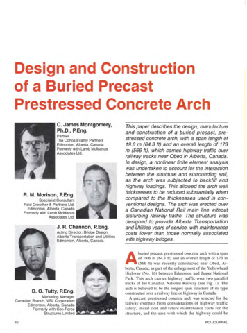
Table 3. Condition of joints.Department ConnecticutI Illinois Californial hAge -.INonereported.!.!.!.!.!--I-- None-Maine'I in. epoxy waterproofing overlay (did not work properly)IndianaNone-------WashingtonWaterproofing membrane system with Class I (bituminous surfacing)Low-slump dense concrete (LSDC) 2 in . -Iowa- - Connecticut--Waterproo fing membrane system with Class I------New YorkWaterproofing membrane system with Class IOhioWaterproofing membrane system with Class IOntario, CanadaWaterproofing membrane system with Class I-----Illinois- -2 in. minimum Class I with waterproofi ng membrane syste m--Ca li forniaEpoxy concrete overlayMaryland2 in. latex modified concrete---VirginiaNote: I in . 25.4---Not reportedTexas Waterproofing membrane system with Class I and II111111 .With advancements in precastingtechnology , there has been a justifiable trend towards the application oflow cost, full depth precast concretebridge deck replacement as an alternative to conventional bridge deck systems. In this type of construction, theentire bridge deck is constructed ofprecast concrete. There is no additional field-cast concrete acting structurally, except that used in the connections and slab closures.A view of the system is shown inFig. 1, where the precast concrete panels are being placed on the existingJanuary-February 1995--r.!.!.!.!-.!---.I.I--- .II.IIProtection systems -I -------jTable 4. Type of protection systems.Alaska8'IIr-r--IIDepartment f- Deterioration Maryland- supporting elements. Fig. 2 shows thetransverse joint between adjacent precast panels along with the openingsfor the shear connector pockets.The advantages of this system canbe summarized as follows: '·j1. This type of construction is applicable to all requirements of repairor replacement, as well as for newbridge construction.2. Prefabrication of components cansignificantly reduce the out-of-servicetime for bridge repair or replacement.3. Cost savings are possible becauseof the reduction in the employed fieldlabor and the reduction of the addedexpenses of the bridge users due to thedecrease in traffic delays.Prior to 1975 , research was conducted on the use of precast , prestressed concrete bridge deck panels. 6In addition, research also includedtesting for the feasibility of usingthese types of systems.'In 1982, a survey conducted by thePCI Bridge Committee revealed that21 states utilized precast, prestressedconcrete bridge deck panels regularlywhile another seven states were starting to incorporate the method throughbidding options or by developing details prior to trial projects. 8 In 1986,another survey was conducted by thePCI Bridge Producers Committeefrom which specifications governingthe design of such systems were developed; as a result, a recommendedpractice for precast composite bridgedeck panels was published. 9QUESTIONNAIRE SURVEYAt the start of this investigationthere was no systematic method foridentifying and evaluating the performance and durability of precast, prestressed concrete bridge decks, especially under severe environmentalconditions. In order to identify theproposed bridge deck system in NorthAmerica, a detailed questionnaire survey was sent to 53 departments oftransportation (DOTs), transportationand thruway authorities and turnpikes ,in the United States and Ontario,Canada.61
91'-10' out to oiA of brieNO. 1439- ATlGUN RIVER NO. 1 BRIDGENO. 1257- SOUTI-i FORK BONANZA CREEK BRIDGEFig. 3. Elevation of Bridge Nos. 1439 and 1257- Dalton Highway Bridgerehabilitation .Fig. 4a. Existing typical section -Dalton Highway Bridge rehabilitation.Extend Deck and reverse Railingif necessary to provide 13' -6'minimum roadway Remove 13'-6' of Superstructureand Pile CapSTAGE InrmRemove this half of Superstructureand Pile Cap after half-widthconstruction shownSTAGE IIFig. 4b. Construction Stages I and II 62Dalton Highway Bridge rehabilitation .PCI JOURNAL
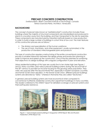
27'-0' RoadwayII Roadway13'-6'Precast, prestressedconcrete deck units13'-6'IRemove temporary deckinstall permanent full-widthDeck and RailingsField spliceNew W16x50 (A36) Pile CapNew W16x50 (A36) stringersSTAGE IllFig. 4c. New typical section -3No . 6 Barstop & bottom1'-5'.5'-7-1'-6'1'-6'-1'-2'Dalton Highway Bridge rehabilitation .27'-5 3/8' r-3 No.6 Barstop & bottomty5 Scaces a12'-2'7'1'-9 11/16'H · 1 : 5 ' 5 'I I I iEnd of Bridge jEND PANELS AT ABUTMENTS5'-7'L 4' x4' x1/2' with7/8' x4' studs buttwelded in cornerspaced at 1'-0'.(Typical for Panelsat end of bridgesand at expansion joints)SECTION B-B.1'-3112"4'-10'I 3@ 5 '.1'-3112"I I27'-5 3/8'3N o. 6 BarsNo.6 Barstop & bottom 3top& bottom tit·5 Soaces at 2'-2'II7' I1'-911/16'· · INTERIOR PANELSSpacing of GroutPoc1.kets. 1.1·-2·I4'-10'2'-6'I1·-2·IC. § \; \ I{ § I (I)63/ 1 1'-31/2'13sp.@ 5' 11 '-3 1/2'Spacing of PrestressingStrandsI-!16 3/ 4!. '.:.L.SECTION A-AFig. 5a. End and interior panels for 30 ft (9.14 m) spans rehabilitation.January-February 1995Dalton Highway Bridge63
2. Period of construction2No . 6 Barstop & bottom.53/4"103/4"1'-3"103/4"53/4"3. Bridge dimensions and orientation27'-5 3/8'-- - -- -- -- -- -- -- No.6 BarsTop&bottom,Cf 4'·2' II4'·2'4'·2'I1'.()"I Ill1'-2 11/16'-!;!""-.'-2 1/4".4'·1 o·· 1/4"711 .- ·INTERIOR PANELSSECTION C-CFig. 5b. Panels for 60ft (18.3 m) spans- Dalton Highway Bridge rehabilitation .SUMMARY OFSURVEY RESPONSES27'·5 3/8'ct Roadway13'-8 11/16"113'-8 11/16"-.·.v.:-:.-. . . v .·.;.:-Y,. - . .·.:. .;.:-. . . . . . . . . . . . .1/2'Fig. 6. Panel elevation- Dalton Highway Bridge rehabilitation.Polypropyleneor PolyethyleneRod form1/2'Fig. 7. Typical joint- Dalton HighwayBridge rehabilitation.The objective of this investigationwas to evaluate the stability, durability, and performance of the proposedbridge deck system exposed to harshconditions . Over the years , manystates have experimented with precastconcrete slabs for deck replacementsby offering a wide variety of designand construction methods. The firsttrials were started in the early 1970sby Indiana, 10 New York, and Alabama. 11 All these early applications644. Deck supporting system5. Deck dimensions and specifications6. Panel dimensions and reinforcement7. Concrete strength8. Type of connecting system between panels and supporting system9. Type of joints between adjacentpanels10. Type of bonding material used tofill the joints11. Problems associated with the joints12. Reasons for adverse results13. Type of protection systemThe returned questionnaires werecompiled and analyzed. The summarized results are presented in the following text and tables.had approximately the same characteristics. The spans did not have anyskew or superelevation. More projectsinvolved new construction rather thanrehabilitation. The deck-stringer system was primarily noncomposite, although some composite action wasobserved.Significant advances have beenmade since the rnid-1970s through thebeginning of the 1980s. Many of thespans were composite and some involved complex geometries . Majorstructures were built nationwide by theNew York State Thruway Authority(NYSTA), the New York State Department of Transportation (NYSDOT), the Maryland State HighwayAdministration (MSHA), and the Illinois Department of Transportation(IDOT).The following information was requested in the survey:1. Type of construction and numberof bridges builtThirteen states , namely , Alaska,Maine, Indiana, Washington, California, Iowa, Connecticut, Maryland,New York, Ohio, Texas, Virginia, andIllinois, and Ontario, Canada, have reported using the precast, prestressedconcrete bridge deck system. Table 1presents the complete response of thedepartments , the number of departments that reported using this concept,and the number of departments interested in using this concept of construction in the future.Some of the departments have usedthe precast, prestressed concretebridge deck system for rehabilitation ,including Alaska, Maine, Connecticut,Maryland, Ohio, Texas, Illinois, Virginia, and Ontario, Canada; some haveused the system for new construction,including Indiana, Washington , andIowa; and some have used the systemfor both rehabilitation and new construction, including California andNew York. Table 2 presents the number of bridges constructed in eachstate and the type of construction.The joints are important becausebridge deck performance is manifestedin the behavior of its joints. The survey focused on the problems associated with the joints and the reasons forthe adverse results . Unfortunately,most of the departments have ignoredPCI JOURNAL
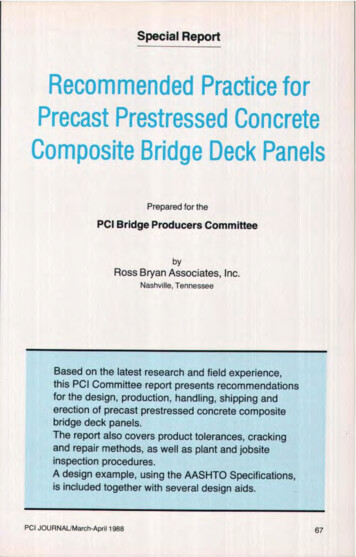
Key around hole(Typ. all holes)1 1/2'x3 1/2'SHEAR POCKETFOR 30-FT SPANSSHEAR POCKETFOR 60-FT SPANSFig. 8. Shear connectors for 30 and 60ft (9.14 and 18.3 m) spans- DaltonHighway Bridge rehabilitation.Fig. 9. Existing typical section - Chulitna River Bridge redecking.New Longitudinal Steel Trussesthis portion of the survey due to lackof manpower for bridge investigationand maintenance. The condition of thejoints is presented in Table 3. Materialquality, construction procedures, andmaintenance are the main reasons foradverse results, as demonstrated inMaine and Indiana.Due to the harsh weather conditionsin the northern regions, the surveyalso addressed the protection system.Few states have reported using a protection system and very few states reported that the protection system usedis performing satisfactorily. Differenttypes of protection systems wereused. Maine has used a 1/4 in. (6 mm)epoxy waterproofing overlay, yet, according to their report, this did notwork properly. Washington and Connecticut reported using a waterproofing membrane system with Class I,and Iowa reported using low-slumpdense concrete with a thickness of2 in. (50 mm). The collected data arepresented in Table 4.Every department of transportationhas used its own method of design andconstruction. The study introduced selected applications in a few states, suchas Alaska, Maine, Indiana, Washington,California, Iowa, Connecticut, Maryland, New York, Ohio, Texas, Virginia,and illinois, as well as Ontario, Canada.This paper will present the projects accomplished recently in these states.ALASKA DOT ANDPUBLIC FACILITIESThe Alaska rehabilitation programincluded two main projects that werecompleted in October 1992: the Dalton Highway Bridge rehabilitation andthe Chulitna River Bridge redeckingprojects.Dalton Highway BridgesFig. 10. Stage construction - Chulitna Rive r Bridge redecking.January-February 1995The first project contained 18 bridgesin one contract. The existing bridgeshad timber decks supported on eithersteel stringers or timber floor beams,depending on the bridge span length.Steel stringers were used for spans of60 ft (18 m) and timber stringers wereused for spans of 30 ft (9 m), as shownin Fig. 3. The rehabilitation process re65
Fig . 11. New typical section - Chulitna River Bridge redecking.Cast-in-place SectionI18' min. MambraneWaterproofingcentered over alljolnla.Fig. 12. Deck panel layout- Chulitna River Bridge redecking . tRoadway12'-0 5/8'8 '-0'13'-0 5/8'timber or concrete deck. At the end ofthis stage, one-half of the bridge widthwas ready to support traffic flow.The second stage was to work on theother half width, where new pile capsand stringers were installed. Finally, thetemporary deck was removed , fieldsplices between the separated pile capswere assembled, and permanent, fullwidth precast, prestressed concrete panels were installed. The stage construction is shown in Figs. 4a, 4b, and 4c.The difference in stringer sizes dueto the difference in span lengths led tothe use of various types of precastpanels, as shown in Figs. 5a and 5b.All precast panels were 9.5 in. (240mm) thick at the centerline of theroadway and 7.5 in. (190 mrn) thick atthe edges, with one typical length of27 ft 5 3/s in. (8.4 m) and two typicalwidths of 4ft 10 in. and 5 ft 7 in. (1.5and 1. 7 m). Fig. 6 shows a typicalpanel elevation. Normal weightconcrete was used with a strengthof 5000 psi (34 MPa) at transferand 6500 psi (45 MPa) at 28 days .The prestressing strands were 1/z in.(13 mm) diameter, seven wire, low relaxation strands with an ultimatestrength of 270 ksi (1860 MPa). Thejacking stress for the pretensioningstrands was 189 ksi (1300 MPa) andthe effective stress after all losses was149 ksi (1030 MPa).A typical female-to-female joint(see Fig. 7) was used between adjacentpanels and an elastomeric compression joint seal was used in the expansion joint.Two sizes of shear pockets wereused. The first pocket size is 7 x 5 in.(180 x 130 mm) with two studs 7/s x6 in. (20 x 150 mm) installed in eachpocket for a 30 ft (9 m) span length.The second pocket size is 12 x 5 in.(300 x 130 mm) with three studs of thesame size installed for a 60 ft (18 m)span length, as shown in Fig. 8.Fig. 13. Edge area plan - Chulitna River Bridge redecking.Chulitna River Bridgemoved the existing timber decks, railings, stringers, and pile caps, and installed permanent full width, full depthprecast, prestressed concrete deck panels on new steel W shape (wide flange)stringers and pile caps.Stage construction was adopted to66maintain traffic flow during construction. The primary stage consisted ofremoving a half width of the superstructure and pile caps and installing atemporary railing at the free end. Thenew steel pile caps and stringers wereinstalled and covered by a temporaryThe second project was the redecking of the Chulitna River Bridge. Thebridge has a total span length of 790 ft(240 m) and a total width of 34 ft(10 m). The existing structure has aconcrete deck on steel trusses andstringers, as shown in Fig. 9.PCI JOURNAL
of #5 Bars Top & Bottoms:: :::: ::::::(: : ::.J.7112]) : : :1#6 Bars @ 6' Top & Bottom1 TSECTION TAKEN NEAR (tROAOWAYFig. 14. Typical Panel A- Chulitna River Bridge redecking.l 2'x1 1/2' X1/4'x0'-6' long1/2' (Typ.)-i 1, - - - No. 4 Bar1'-8' longepoxy coatedVIEW A-AFig. 15. Shear connector detail -Chulitna River Bridge redecking.1'x8 11'2' 50 OurometerElaatomeric Bearing Padfull length of trussesPrecast ConcreteDeck PanelThe new construction required removal of the 34ft (10m) wide cast-inplace deck and replacement with 42ft2 in . (13 m) wide full-depth precastconcrete deck panels . A stage construction was adopted in order tomaintain the traffic flow during the rehabilitation process. The stage construction was very similar to thatused on the first project, as shown inFig . 10. The new typical section isshown in Fig. 11.Three types of precast panels, A, Band C, were used to fit the geometryof the deck, as shown in the deckpanel layout and edge area plan (seeFigs. 12 and 13).Norma l weight concrete with astrength of 5000 psi (34 MPa) andepoxy coated mild steel reinforcementwere used. The elevation of a typicalPanel A and the cross sections areshown in Fig. 14. A typical female-tofemale joint was used between the adjacent panels, which is similar to thejoint used in the Dalton HighwayBridge rehabilitation (see Fig. 7). Thejoint has the same configuration; however, the dimensions are different.A system of two 2 x 1 1h x 1/ 4 in. (50x 38 x 6 rnm) steel angles 6 in . (150mm) long, 3 x 1/ 4 in. (75 x 6 mm) steelplates 4 in. (100 mm) long, and fourNo. 4 bars 1 ft 8 in. (510 mm) longwas used as a shear connector (seeFig. 15). Magnesium-phosphate groutwas used to fill the pocket.Two types of connections betweenthe panels and the supporting systemwere used . Details of the bolted connections on truss elements includingalso the grouted pocket connections onthe steel stringers are shown in Figs.16 and 17. The design called for theuse of two different types of connections for two reasons. First, the trussflanges were too narrow for a groutedpocket connection, and second, thebolted connection provided some support for the structure prior to grouting.IOWA DOT,jWI---It3/4'x7' x8' w/long.slotted hole 2'x1 1/16'Existing W21x44BOLT DETAIL @TRUSSESFig. 16. Bolted connection - Chulitna River Bridge redecking .January-February 1995One bridge under construction utilizes full-depth precast, prestressedconcrete deck panels that are designedto act compositely with the steel floorbeams and girders. This cable-stayedbridge over the Mississippi River at67
Precast ConcreteDeck Panel2 1/2" Polyethylene Rodsalong full length of girder glue to steel prior toSetting Deck PanelsLeveling screws were used to adjustthe level of the precast panel s, asshown in Fig . 22. A 2 in. (50 mm)layer of low-slump dense concrete wasused as protection for the precast deck.The Iowa DOT has not utilized thistype of deck construction in the past,so they could not comment on the performance and durability of the precastdeck construction.Existing Girder - - ; - . - CONNECTICUT DOTGROUT POCKET DETAIL@ GIRDERFig. 17. Grouted connection - Chulitna River Bridge redecking.4:!Pier North Edge G irder37'eSouth Edge GirderCable ConnectionBlackout (Typ.)Fig. 18. Portion of precast slab panel plan of Transportation.Burlington, Iowa, is 87.5 ft (27 m)wide and 1065 ft (325 m) long withtwo spans of 660 and 405 ft (20 I and124 m). The support system consists oftransverse floor beams, with a spacingof 15 ft (4.6 m), carried by two girdersat the north and south bounds. The precast panels were 10 in. (250 mm) thick,13 ft 9 in. (4.2 m) long, and 47 ft 3 in.or 38 ft 3 in. (14.4 or 11.7 m) wide.They were installed transversely on thefloor beams, as shown in Fig. 18.A variety of precast panel typeswere needed to meet the post-tensioningrequirements in the longitudinal direction. Two panel types are shown inFig. 19.Post-tensioning in the transverse direction was applied to the panels forhandling and erection, as shown inFig . 20. The entire post-tensioning68Burlington Bri dge, Iowa Departmentsystem (thread bars, nuts, couplers,and anchor plates), except the ducts,was epoxy coated. The initial posttensioning force was 89 kips (396 kN)for the 1 in. (25 mm) diameter threadbar and 166 kips (738 kN) for the P/sin. (35 mm) diameter thread bar. Castin-place concrete was used to fill the24 in . (610 mm) wide longitudinaland 15 in. (380 mm) wide transversejoints.The shear connector pockets were9 in. (230 mm) long and 3 in . (75mm) wide. All of these pockets weredistributed on the edge girders with aspacing of 9 in . (230 mm). Fig . 21shows the plan and cross section ofthe shear connector pockets . Nonshrink grout was used to fill the pockets and the space between the precastpanels and girder flanges.The Connecticut DOT is currentlyundertaking a 7 billion InfrastructureRenewal Program . Part of this program involves the rehabilitation of approximately 1640 bridges at an estimated cost of 1.6 billion. Many ofthese bridges involve complete deckreplacements requiring complicatedstage erection seque nces and occasional bridge closures during construction. In an attempt to expedite the construction process, a design usingprecast concrete deck slabs was incorporated for one of the structures (Connecticut Bridge 03200).Prior to the slab design, researchwas undertaken to evaluate proper design and construction methods in orderto accomplish deck replacement in theshortest time possible. The procedureof using night closures and day openings to provide uninterrupted peakhour service was not applicable forthis project for two main reasons:1. Bridge 03200 is a compositeplate girder bridge; as a result, removal of the existing composite deckwould be a time consuming processdue to the existing shear connectors.2. The possibility of avoiding significant overstress in the girders atthe midspan a rea , where a smallnon-composite joint would occur between the old slab and the new precastdeck during construction, had to beavoided.For these reasons, it was decided toshut down the bridge for the reconstruction period because a reasonabledetour existed nearby.This six-span bridge has a totallength of 700ft (213 m) consisting ofstraight composite plate girders running on tangents from pier to pier.Three of the spans are continuouswith a hung span supported by pinsPCI JOU RNAL
and hangers. The structure is locatedon a horizontally compound curve requiring various degrees of deck superelevation.To account for the curvature, eachslab was designed as a trapezoid. Oneend of the slab would be 8 ft (2.4 m)wide and the other slightly less, depending on the curvature. Two different shapes were chosen because thereare two different curves on the structure. Because the bridge is only 27 ft6 in. (8.4 m) wide, it was decided touse full width precast panels with 8 ft(2.4 m) width, 26 ft 8 in . (8.1 m)length, and 8 in. (200 mm) depth. Fig.23 shows a typical section of the precast concrete slabs.Because the slabs had to be composite, blockouts were required to allowfor the installation of shear connectors. This would mean that the transverse location of the blackouts wouldbe different for each slab. A coordinated geometry CADD program wasused to calculate the required locationsof all the blackouts. It was determinedthat by oversizing the blockouts, theirlocation in the slabs could be limitedto three different patterns.The shear connector blackouts wererectangular, 18 x 5 in. (460 x 130 mm)at the top and tapered from top to bottom. The spacing of these blackoutswas 2 ft (610 mm) on centers for eachslab. Three 7/s in. (22 mm) weldedstud shear connectors were placed ineach blockout, as shown in Fig. 24.The length of the precast panel doesnot allow full development; hence, acomplete prestressed concrete designfor the slabs was not possible. Thus,the slabs were designed using epoxycoated reinforcing steel, with a minimal amount of prestressing needed toprevent cracking during handling andinstallation.A leveling bolt system was used forgrade adjustment in the field. The boltwould be cut below the surface of theslab and the void grouted (see Fig. 25).A standard shear key configurationfilled with high strength, non-shrinkgrout was chosen for the transversejoints (see Fig. 26). Longitudinal posttensioning was designed to provide continuity. The design called for three 0.6in. (15 mm) diameter strands per cut.The strands were pulled through plasticJanuary-February 1995Aoori oam 13'-9' 47'-3'Shear ConnectorPockets2'TYPE S1 47'-3'Shear ConnectorPocketsI3'-4'TYPE S3Fig. 19. Precast slab panel Types S1 and S3- Burlington Bridge, IowaDepartment of Transportation. 1' Dia. Post-Tensioned Bar (Typ. All Panels)4 1 3/8' Dla. Post-Tensioned Bar (Some Panels)1'-6'Panel WidthFig. 20. Post-tensioning profiles in precast slab panels Department of Transportation.Burlington Bridge, Iowa69
SECTION A-AFig. 21. Shear connectors- Burlington Bridge, Iowa Department of Transportation.Precast Slab Panel3/4' min. width form Stripwith 1/2' dia. bleederholes at 2' -0' ctrs.Fig. 22. Leveling screws detail at floor beam- Burlington Bridge, Iowa Departmentof Transportation .Fig. 23. Typical section of precast concrete slabs- Bridge 03200, ConnecticutDepartment of Transportation.70PCI JOURNAL
Blackout for Installation7/8' Welded StudT8'lSECTION A-AFig. 24. Typical shear connector blackout- Bridge 03200, Connecticut Departmentof Transportation .pFig. 25. Typical section at leveling bolt- Bridge 03200, Connecticut Department ofTransportation.Non-Shrink GroutFoam Backer RodFig. 26. Standard shear key configuration of Transportation .January-February 1995Bridge 03200, Connecticut Department71
ducts that were spliced at each transverse joint through small blackouts. Anarbitrary stress of 150 psi (1.03 MPa)was chosen for the simple spans andwas appreciably increased to 300 psi(2.07 MPa) in the three-span continuousportion of the bridge to account for thesignificant composite dead load and liveload stresses. After the strands were installed and tensioned, the ducts werecompletely grouted.At the end of each span, a smallcast-in-place closure pour was used toaccount for time-dependent deformations in the precast slabs and to protectthe post-tensioning system, as shownin Fig. 27. In order to properly seal thedeck, the finished slab was toppedwith a membrane waterproofing system and a 2 112 in. (65 mrn) bituminouswearing surface.Fig. 27. Closu re pour - Bridge 03200, Connecticut Department of Transportation.rMAINE DOTThe selected project was the deckreplacement of the Deer Isle-SedgwickBridge over Eggemoggin Reach between Little Deer Isle and Sedgwick(Project No. BH-0250). The bridgeconsists of nine spans : four at 65 ft(20 m), one at 484 ft (148 m), one at1080 ft (329 m), one at 484ft (148 m),and two at 65 ft (20 m), with a totalwidth of 23.5 ft (7.2 m) center to center of the suspended girders.Two alternative solutions were presented by the designer. Alternate I wasa concrete filled steel grid deck (including the main 1-beam spacing); Alternate II was a precast concrete slabdeck. Selection of either Alternate I orAlternate II was the contractor's option. Fig. 28 shows the cross sectionfor the two alternatives. The supporting deck system consisted of twotypes of suspended transverse girders- WF14 x 42 for approach spans andWF24 x 74 for suspended spans, withfloor beams in between.Alternate II was adopted for the redecking process. The work started inMay 1987 and was completed in October 1987 without major traffic interruption. The lightweight precast concrete deck panels were designed tocover a half width of the bridge tomaintain traffic flow during construction. The panels were 6 112 in. (165 mm)thick, 9 ft 11 in. (3 .0 m) wide and of72ALTERNATE N0. 1Section at Suspender ConnectionConcrete Filled Steel Grid Flooring ShownFig. 28. Deck construction alternates Department of Transportation.variable length depending on the spacing of the suspended girders. Fig. 29shows the plan and cross section of theblackouts. The welded connectionblackout detail is shown in Fig. 30.A typical female-to-female transverse joint was chosen (see Fig. 31 ).Joints and blackouts were filled withepoxy mortar after the shear connectors and plate connections werewelded. No prestressing was appliedto the slabs. Epoxy coated reinforcingsteel was used.All the panels had a 1/4 in. (6 mm)epoxy waterproofing overlay appliedprior to erection. The overlay coveredthe entire top surface of the panelswithin 6 in. (150 mrn) of any blackoutor shear key. After the shear keys andblackouts were filled, the epoxy waterproofing overlay was placed over theseAI.TERNATE NO. 2Section at Floorbeam Be'-n SuapendersLightweight Prec
Cali fornia Epoxy concrete overlay -Maryland 2 in. latex modified concrete ----Texas Not reported -- Virginia Waterproofing membrane system with Class I and II Note: I in. 25.4 111111 . With advancements in precasting technology, there has been a justifi able trend towards the application of low cost, full depth precast concrete