Transcription
Introduction to Turning Toolsand their ApplicationIdentification and application of cutting tools for turningThe variety of cutting tools available for modern CNC turning centers makes it imperative formachine operators to be familiar with different tool geometries and how they are applied tocommon turning processes.This course curriculum contains 16-hours of material for instructors to get their studentsready to identify different types of turning tools and their uses. 2016 MachiningCloud, Inc. All rights reserved.
Table of ContentsIntroduction . 2Audience . 2Purpose . 2Lesson Objectives. 2Anatomy of a turning tool. 3Standard Inserts . 3ANSI Insert Designations . 3Insert Materials . 9Seat . 10Tool Holders . 11Boring Bars . 13Drills, Taps and Reamers . 13Twist Drills . 13Indexable Drills. 14Spot Drills and Center Drills . 14Taps and Single Point Thread Tools . 15Reamers . 15Feeds and Speeds. 16Cutting Speed . 16Feed Rate . 17Selection of Tools, Feeds, and Speeds . 18 2016 MachiningCloud, Inc.Introduction 1
IntroductionTurning generates axially symmetric shapes with a single-point tool. A single-point tool removesmaterial by means of one cutting edge. In most cases the tool is held in a fixed position with theworkpiece rotating about a turning axis. There are also tools held on the spindle centerline(drills, reamers, taps) for hole-making applications that have speed and feed limitations.AudienceThis class is intended for entry-level turning operators and students in a turning operatortraining program who have a basic understanding of turning machines and their operation. Thislesson is also useful to anyone interested in the metalworking industry who wants to gainknowledge about material removal in CNC machining.PurposeLearn how to identify the components of common turning tools and how those tools are usedin everyday turning processes. Students are introduced to ANSI turning insert nomenclature,tool holders and boring bars. They also learn about tools used for centerline machining such astwist drills, taps and reamers. Students finish with an introduction to the concepts of spindlespeeds and feed rates.Lesson ObjectivesAt the end of this lesson, you will know how to: Identify the components of common turning toolsIdentify the basic shapes of turning insertsIdentify basic tool holders for external and internal turningIdentify common types of tools for drilling and threadingIdentify the main groups of cutting tool materialsUnderstand the applications for common turning toolsUnderstand the difference between cut speed and feed rateUnderstand the difference between Revolutions Per Minute (RPM) and ConstantSurface Speed (CSS)Understand the difference between Inches per Revolution (IPR) and Inches per Minute(IPM) 2016 MachiningCloud, Inc.Introduction 2
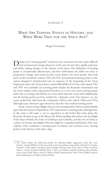
Anatomy of a turning toolMost turning is done using a replaceable insert that is gripped in a turning tool body, which isthen mounted on the lathe turret.Standard InsertsTurning inserts employ highly engineered composite structures, coatings, and geometryfeatures to achieve great accuracy and high material removal rates.The benefits of using replaceable inserts for turning tools include: Some inserts can be indexed to use other edges when one becomes wornInserts are quickly and easily replaced at the machineANSI Insert DesignationsThe American National Standards Institute (ANSI) has developed a coding system of numbersand letters to describe the shape, dimensions, and important parameters of turning inserts.CNMG1234Shape Clearance Tolerance Type 2016 MachiningCloud, Inc.-4325I.C.Size6Thickness7NoseRadiusAnatomy of a turning tool 3
1. Insert ShapeTurning inserts are manufactured in a variety of shapes, sizes and thicknesses. The shapecan be round to maximize edge strength, diamond-shaped to allow a sharp point to cut finefeatures, square, or even octagonal to increase the number of separate edges that can beapplied as one edge after another wears out. A parallelogram 85 B parallelogram 82 C diamond 80 D diamond 55 E diamond 75 H hexagonK diamond 55 L rectangleM diamond 86 O octagonP pentagonR roundS squareT triangleV diamond 35 W - trigon 80 C and W type turning inserts are often used for rough machining due to their larger pointangle, which makes them more rigid. Inserts with a smaller point angle, such as D and V,are often used for finish machining. Although they have less strength, the smaller angle canreach more part details.Large point angle: Stronger cutting edge Higher feed rates Increased cutting forces Increased vibrationSmall point angle: Weaker cutting edge Increased access to part details Decreased cutting forces Decreased vibration 2016 MachiningCloud, Inc.Standard Inserts 4
2. ClearanceMost inserts have drafted faces onthe walls. Clearance prevents thewalls of the insert from rubbingagainst the part, which willgive poor machining. However, aturning insert with a 0 clearanceangle is mostly used for roughmachining.3. ToleranceLetterABCDEFGMUInscribed Circle (I.C.) .0002 .0002 .0005 .0005 .001 .002 to .004 .001 .002 to .010 .005 to .012 2016 MachiningCloud, Inc.Thickness .001 .005 .001 .005 .001 .002 .005 .005 .005Standard Inserts 5
4. TypeThe turning insert hole shape and chip breaker type. A Cylindrical holeB 70-90 countersink holeC Double countersinkF No hole; Double-sided chipbreakerG Cylindrical; Double-sidedchip breakerH 70-90 countersink; SinglesidedJ Double countersink;Double-sidedM Cylindrical; Single-sidedN No hole; No chip breakerP Cylindrical; Hi-DoublePositive Chip breakerQ 40-60 Double Countersink;No chip breakerR No hole; Single-sidedS Cylindrical; Hi-doublepositiveT 40-60 double countersink;Single-sidedU 40-60 double countersink;Double-sidedW 40-60 double countersinkX Special Design 2016 MachiningCloud, Inc.Standard Inserts 6
4. TypeA chip breaker is a feature in the face of the insert that disrupts the flow of chips such thatthey break into short segments, rather than forming a long, stringy chip.5. SizeThis numeric value tells us the cutting edge length of the turning insert.For equal sided inserts 1/4” I.C. or over:Size Number of 1/8” increments.For equal sided inserts less than 1/4” I.C.:Size Number of 1/32” increments.For rectangles and parallelograms, 2 digits are necessary (Widthand Length).Digit 1: Width in 1/8” incrementsDigit 2: Length in 1/4” incrementsExamples:2 1/4"3 3/8”4 1/2"Examples:2 1/16"3 3/32”4 1/8"Example:12 1/8” x 1/2"Important: The depth-of-cut for roughing should never exceed 1/2 the inscribed circle ofthe insert. 2016 MachiningCloud, Inc.Standard Inserts 7
6. ThicknessThis value tells us the thickness of the insert.For inserts 1/4” I.C. or over: Thickness in 1/16” incrementsFor inserts less than 1/4” I.C.: Thickness in 1/32” increments7. CornerForm on the corner in 1/16” increments for inserts with a corner radius.To reduce vibration, it is often an advantage to choose a nose radius that is smaller thanthe depth of cut.0 Sharp corner (.005R)1 1/64” radius2 1/323 3/644 1/165 5/646 3/327 7/648 1/810 5/3212 3/1614 7/3216 1/4Large nose radius: Increased feed rates Large depths of cut Strong edge security Increased radial pressures 2016 MachiningCloud, Inc.Small nose radius: Small cutting depths Reduced vibration Weak cutting edgeStandard Inserts 8
Insert MaterialsInsert material is typically carbide, though ceramic, cermet or diamond inserts can be applied tomore demanding applications. A variety of protective coatings also help these insert materialscut faster and last longer.Insert MaterialCharacteristicsCemented carbide (HW, HC) HW: Uncoated HC: CoatedThe most common material used in theindustry today. It is offered in several “grades”containing different proportions of tungstencarbide and binder (usually cobalt). Highresistance to abrasion.Cermets (HT, HC)Cermet containing primarily titaniumcarbides (TiC) or titanium nitrides (TiN) orboth HT: Uncoated HC: CoatedAnother cemented material, based on titaniumcarbide (TiC). Binder is usually nickel. Itprovides higher abrasion resistance comparedto tungsten carbide at the expense of sometoughness. Extremely high resistance toabrasion.Ceramics (CA, CM, CN, CC) CAOxide ceramics containing primarilyaluminum oxide (Al2O3) CMMixed ceramics containing primarilyaluminum oxide (Al2O3) but containingcomponents other than oxides CNNitride ceramics containing primarilysilicon nitride (Si3N4) CCNitride ceramics containing primarilysilicon nitride (Si3N4), but coatedChemically inert and extremely resistant toheat, ceramics are usually desirable in highspeed applications, the only drawback beingtheir high fragility. The most common ceramicmaterials are based on alumina (aluminiumoxide), silicon nitride and silicon carbide. 2016 MachiningCloud, Inc.Insert Materials 9
Insert MaterialCharacteristicsCubic boron nitrides (BN)The second hardest substance. It offersextremely high resistance to abrasion at theexpense of much toughness. It is generallyused in a machining process called "hardmachining", which involves running the tool orthe part fast enough to melt it before ittouches the edge, softening it considerably.Polycrystalline diamonds (DP, HC) DP : Uncoated HC : CoatedThe hardest substance. Superior resistance toabrasion but also high chemical affinity to ironwhich results in being unsuitable for steelmachining. It is used where abrasive materialswould wear anything else.SeatA piece of carbide, the same size as the insert it supports, placed between the insert and thebottom of the pocket where the insert fits in the tool holder. 2016 MachiningCloud, Inc.Seat 10
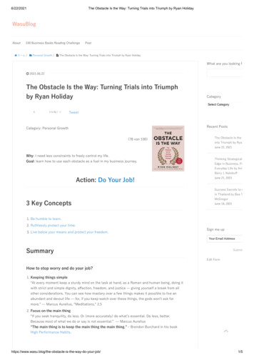
Tool HoldersIt is essential that the insert be supported in a strong, rigid manner to minimize deflection andpossible vibration. Consequently, turning tools are supported in various types of heavy, forgedsteel tool holders.The turning tool body generally does not feature quite so much engineering as the insert, buteven here there are a range of choices for fine-tuning the process. Quick-change tools involvemodular bodies that allow replacement tool bodies to be swapped in and out and locked inplace quickly to minimize setup time. The turning tool body can also channel high-pressurecoolant more effectively to the cutting edge of the tool.The ANSI numbering system for turning tool holders has assigned letters to specific geometriesin terms of lead angle and end cutting edge angle. The primary lathe machining operations ofturning, facing, grooving, threading and cutoff are covered by one of the seven basic tool stylesoutlined by the ANSI system.The designations for the seven primary tool styles are A, B, C, D, E, F and G. 2016 MachiningCloud, Inc.Tool Holders 11
Tool Holders A - G A 0 side-cutting edge angle, straight shank B 15 side-cutting edge angle, straight shank C 0 end-cutting edge angle, straight shank (forcutoff and grooving operations) D 45 side-cutting edge angle, straight shank E 30 side-cutting edge angle, straight shank (forthreading operations) F 0 end-cutting edge angle, offset shank (for facingoperations) G 0 side-cutting edge angle; offset shank (this toolis an 'A' style tool with additional clearance built in forturning operations close to the lathe chuck)Tip: The most commonly used insert/holder combination for O.D. rough turning and facing isthe C type 80 diamond insert with a 3-5 negative lead tool holder. It is often selected becauseit is the best compromise between strength of insert and end-angle clearance. 2016 MachiningCloud, Inc.Tool Holders 12
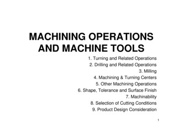
Boring BarsBoring bars are cylindrical bars used for internal machining, typically to produce precise holes.Boring bars are also used for internal turning. Boring bars are available in steel, solid carbide,and carbide-reinforced steel.Boring tools consist of a round shaft with one insert pocket designed to reach into a part holeor cavity to remove internal stock. Boring tools enlarge a hole made by a previous process.Boring bars have the following advantages for hole making: Ensuring precision and straightnessProducing a hole larger than standard drill bit sizesProducing a non-standard size holeProducing a hole with a good finishDrills, Taps and ReamersHigh Speed Steel (HSS) tools such as drills, taps and reamers are commonly used on CNCmachining centers for hole making operations.Twist DrillsTwist drills have a conical cutting point at the tip of a cylindrical shaft that has one or morehelical flutes. The flutes are designed to evacuate chips out of the hole being drilled. Twist drillsare available in a variety of sizes, lengths, materials and coatings, but the most common areHigh Speed Steel (HSS) and solid carbide. 2016 MachiningCloud, Inc.Boring Bars 13
Tool coatings have an influence on the cutting process by increasing cutting speed and tool life.Coatings such as titanium nitride (TiN) increase the initial cost but reduce wear and increasetool life. Applied as a thin coating, TiN is used to harden and protect cutting surfaces.Twist drills coated with titanium nitride (TiN) are easily identified by a gold like color. Thiscoating increases the hardness of the bit and adds a self-lubricating property.Indexable DrillsThe indexable drill is a two-fluted, center-cutting tool with indexable carbide inserts.Spot Drills and Center DrillsSpot drills are designed to be extremely rigid so that they can precisely spot a hole for a twistdrill. The goal is use the spot drill to make a little dimple in the workpiece that keeps the twistdrill from walking so that the hole winds up in the right place.Center drills are intended to be used to create a 60 center in the end of lathe stock. They havea 2-part tip that has a small pilot as well as the larger countersinking area of the bit. 2016 MachiningCloud, Inc.Drills, Taps and Reamers 14
If you use a carbide drill, spotting is typically not needed. The carbide itself is so rigid comparedto HSS that the drill will go where it is pointed.Taps and Single Point Thread ToolsTaps are used to cut internal threads of a specific size and pitch. A tap requires a hole be drilledfirst to the size of the minor diameter.A single point thread mill is a cutter whose shape is the thread form. On a lathe, that cutter issynchronized to the rotation of the part so it perfectly tracks the helix that is a thread.Successive passes cut deeper and deeper to form threads on the interior or exterior of thestock.ReamersReamers are used to enlarge an existing hole to a precise tolerance and to add a high qualitysurface finish. Reamers require a hole be drilled first that is fairly close to the final size so thatthe reamer actually removes relatively little material. Reamers ensure a hole has an accuratediameter, roundness, and good surface finish. 2016 MachiningCloud, Inc.Drills, Taps and Reamers 15
Feeds and SpeedsFeeds and speeds refer to two separate velocities for machine tools: feed rate and cuttingspeed. They are used together because of their combined effect on the cutting process. Cut speed is the speed at the outside edge of the part as it is rotating, also known assurface speedFeed rate is the velocity at which the cutter is advanced along the spinning workpieceCutting SpeedCutting speed is the speed that the material moves past the cutting edge of the tool. Cut speedcan be defined as revolutions per minute (RPM) or as surface feet per minute (SFM).Revolutions Per Minute (RPM) relates directly to the speed, or velocity, of the spindle. Itannotates the number of turns completed in one minute around a fixed axis. RPM maintainsthe same revolutions per minute throughout the entire operation.RPM mode is useful for: Center cutting operations (drilling)When the diameter at the beginning and end of a cut only differs slightlyDuring threading to allow the perfect synchronization between spindle revolution and Zaxis motion to allow precise threadsSurface Feet Per Minute (SFM) is a combination of the cut diameter and RPM. The faster thespindle turns, and/or the larger the part diameter, the higher the SFM.If two round pieces of different sizes are turning at the same revolutions per minute, the largerpiece has a greater surface speed because it has a larger circumference and has more surfacearea. As the tool plunges closer to the center of a workpiece, the same spindle speed will yield adecreasing surface speed. This is because each revolution represents a smaller circumferentialdistance, but takes the same amount of time.Most CNC lathes have CSS (constant surface speed) to counteract the natural decrease insurface speed, which speeds up the spindle as the tool moves closer to the turning axis. CSSadjusts the revolutions per minute to maintain a constant surface speed at every distance fromthe center. 2016 MachiningCloud, Inc.Feeds and Speeds 16
CSS is useful for: A uniform surface finishWhen the diameter at the beginning a cut will differ significantly from the diameter atthe end of the cutBetter tool life and machining time because tools will always cut at the appropriatespeedMaterials will run better at specific SFMs. SFM is a constant, with RPM as a variable based uponcut diameter.When the SFM constant is known for a specific material, the formulas below can be used todetermine spindle speed:RPM SFM x (12/Pi) / Cut DiameterSo, for an SFM of 400 and a cut diameter of 5", RPM can be found:RPM 400 x 3.82 / 5 306 RPMWhen RPM is known, SFM can be found as follows:SFM RPM x Cut Diameter x Pi/12For example, if you have a cut diameter of 5” and a spindle speed of 306 RPM, then:SFM 306 x 5 x .262 400 SFMFeed RateFeed rate is the velocity at which the cutter is advanced along the workpiece. Feed rate isexpressed as units of distance (inch) per minute or per single revolution.Feed rate can be defined as inch per minute (IPM) or inch per revolution (IPR). IPR is morecommonly used.Values for IPR and IPM are easily converted with the following formulas:IPM IPR x RPMIPR IPM / RPMSo, for a spindle speed of 306 RPM and a feed rate of .01 IPR, the IPM can be calculated asfollows:IPM .01 x 306 3 IPM 2016 MachiningCloud, Inc.Feeds and Speeds 17
Selection of Tools, Feeds, and SpeedsCutting tool selection has a direct impact on the proper programming of feeds and speeds atthe machine.However, many other variables that affect feeds and speeds are: Workpiece material class and conditionWorkpiece diameterCutter materialCutter geometryType of cutDepth of cutCondition of the machineCutting tool manufacturers publish the general feeds and speeds and recommended usage forthe application. Cutting tool manufacturers are often a good place to start forrecommendations on tool selection and feeds/speeds since they rely on customer loyalty. Thecustomer (or potential) should select an insert and grade based on the vendor’srecommendation. 2016 MachiningCloud, Inc.Feeds and Speeds 18
The variety of cutting tools available for modern CNC turning centers makes it imperative for machine operators to be familiar with different tool geometries and how they are applied to common turning processes. This course curriculum contains 1