Transcription
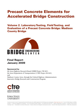
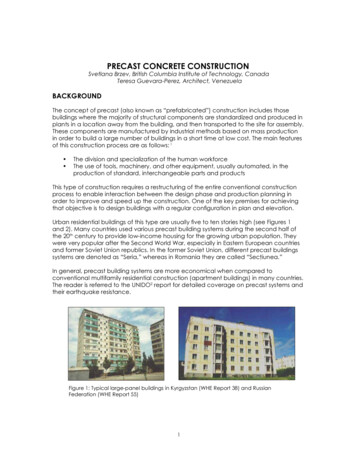
PRECAST CONCRETE CONSTRUCTIONSvetlana Brzev, British Columbia Institute of Technology, CanadaTeresa Guevara-Perez, Architect, VenezuelaBACKGROUNDThe concept of precast (also known as “prefabricated”) construction includes thosebuildings where the majority of structural components are standardized and produced inplants in a location away from the building, and then transported to the site for assembly.These components are manufactured by industrial methods based on mass productionin order to build a large number of buildings in a short time at low cost. The main featuresof this construction process are as follows: 1 The division and specialization of the human workforceThe use of tools, machinery, and other equipment, usually automated, in theproduction of standard, interchangeable parts and productsThis type of construction requires a restructuring of the entire conventional constructionprocess to enable interaction between the design phase and production planning inorder to improve and speed up the construction. One of the key premises for achievingthat objective is to design buildings with a regular configuration in plan and elevation.Urban residential buildings of this type are usually five to ten stories high (see Figures 1and 2). Many countries used various precast building systems during the second half ofthe 20th century to provide low-income housing for the growing urban population. Theywere very popular after the Second World War, especially in Eastern European countriesand former Soviet Union republics. In the former Soviet Union, different precast buildingssystems are denoted as “Seria,” whereas in Romania they are called “Secţiunea.”In general, precast building systems are more economical when compared toconventional multifamily residential construction (apartment buildings) in many countries.The reader is referred to the UNIDO2 report for detailed coverage on precast systems andtheir earthquake resistance.Figure 1: Typical large-panel buildings in Kyrgyzstan (WHE Report 38) and RussianFederation (WHE Report 55)
Precast Concrete ConstructionFigure 2: A typical precast slab-column building(WHE Report 68, Serbia and Montenegro)CATEGORIES OF PRECAST BUILDING SYSTEMSPrecast buildings constitute a significant fraction of the building stock in the republicsof the former Soviet Union and Eastern European countries. These systems have beendescribed in the following eight WHE reports: 32 (Kazakhstan); 33, 38, and 39 (Kyrgyzstan);55 (Russian Federation); 66 (Uzbekistan); 68 (Serbia and Montenegro); and 83 (Romania).Depending on the load-bearing structure, precast systems described in the WHE can bedivided into the following categories: Large-panel systemsFrame systemsSlab-column systems with wallsMixed systemsLarge-Panel SystemsThe designation “large-panel system” refers to multistory structures composed of largewall and floor concrete panels connected in the vertical and horizontal directions so thatthe wall panels enclose appropriate spaces for the rooms within a building. These panelsform a box-like structure (see Figure 3). Both vertical and horizontal panels resist gravityload. Wall panels are usually one story high. Horizontal floor and roof panels span eitheras one-way or two-way slabs. When properly joined together, these horizontal elementsact as diaphragms that transfer the lateral loads to the walls.Figure 3: A large-panel concrete buildingunder construction (WHE Report 55, RussianFederation)
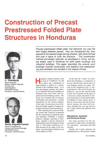
Precast Concrete ConstructionDepending on the wall layout, there are three basic configurations of large-panelbuildings: Cross-wall system. The main walls that resist gravity and lateral loads are placed inthe short direction of the building.Longitudinal-wall system. The walls resisting gravity and lateral loads are placedin the longitudinal direction; usually, there is only one longitudinal wall, except forthe system with two longitudinal walls developed in Kazakhstan (WHE Report 32).Two-way system. The walls are placed in both directions (Romania, WHE Report83).Thickness of wall panels ranges from 120 mm for interior walls (Kyrgyzstan, WHE report 38)to 300 mm for exterior walls (Kazakhstan, WHE Report 32). Floor panel thickness is 60 mm(Kyrgyzstan). Wall panel length is equal to the room length, typically on the order of 2.7m to 3.6 m. In some cases, there are no exterior wall panels and the façade walls aremade of lightweight concrete (Romania, WHE Report 83). A typical interior wall panel isshown in Figure 4.Figure 4: Precast interior wall panel with steel dowels andgrooves (WHE Report 38, Kyrgyzstan)Panel connections represent the key structural components in these systems. Based ontheir location within a building, these connections can be classified into vertical andhorizontal joints. Vertical joints connect the vertical faces of adjoining wall panels andprimarily resist vertical seismic shear forces. Horizontal joints connect the horizontal facesof the adjoining wall and floor panels and resist both gravity and seismic loads.Depending on the construction method, these joints can be classified as wet and dry.Wet joints are constructed with cast-in-place concrete poured between the precastpanels. To ensure structural continuity, protruding reinforcing bars from the panels(dowels) are welded, looped, or otherwise connected in the joint region before theconcrete is placed. Dry joints are constructed by bolting or welding together steel platesor other steel inserts cast into the ends of the precast panels for this purpose. Wet jointsmore closely approximate cast-in-place construction, whereas the force transfer instructures with dry joints is accomplished at discrete points.
Precast Concrete ConstructionFigure 5 shows a plan of a large-panel building from Kazakhstan with the connectiondetails. In this system, vertical wall panel connections are accomplished by meansof groove joints, which consist of a continuous void between the panels with lappinghorizontal steel and vertical tie-bars. Horizontal joint reinforcement consists of dowelsprojected from the panels and the hairpin hooks site-welded to the dowels; the weldedlength of the lapped bars depends on the bar diameter and the steel grade. Vertical tiebars are designed for tension forces developed at the panel intersections.Lateral stability of a large-panel building system typical for Romania is provided by thecolumns tied to the wall panels (WHE Report 83). Boundary elements (called “bulbs” inRomania) are used instead of the columns as “stiffening” elements at the exterior, asshown in Figure 6. The unity of wall panels is achieved by means of splice bars welded tothe transverse reinforcement of adjacent panels in the vertical joints. Longitudinal dowelFigure 5: Plan of a large-panelbuilding showing verticalconnection details (WHEReport 32, Kazakhstan)Figure 6: Atypical buildingplan showingthe locationsof boundarymembers (WHEReport 83,Romania)
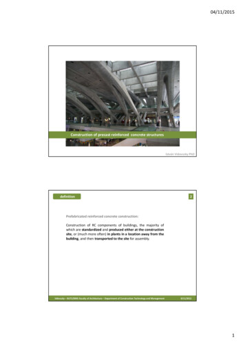
Precast Concrete Constructionbars placed in vertical and horizontal joints provide an increase in bearing area forthe transfer of tension across the connections. Wall-to-floor connection is similar to thatshown in Figure 5.Frame SystemsPrecast frames can be constructed using either linear elements or spatial beam-columnsubassemblages. Precast beam-column subassemblages have the advantage thatthe connecting faces between the subassemblages can be placed away from thecritical frame regions; however, linear elements are generally preferred because of thedifficulties associated with forming, handling, and erecting spatial elements. The use oflinear elements generally means placing the connecting faces at the beam-columnjunctions. The beams can be seated on corbels at the columns, for ease of constructionFigure 7: Components of a precast reinforced concrete frame system ofSeria IIS-04 (WHE Report 66, Uzbekistan)and to aid the shear transfer from the beam to the column. The beam-column jointsaccomplished in this way are hinged. However, rigid beam-column connections areused in some cases, when the continuity of longitudinal reinforcement through thebeam-column joint needs to be ensured. The components of a precast reinforcedconcrete frame are shown in Figure 7.Precast reinforced concrete frame with cruciform and linear beam elements (Seria 106) isan example of a frame system with precast beam-column subassemblages (Kyrgyzstan,WHE Report 33). The system was developed in Kyrgyzstan in 1975. The load-bearingstructure consists of a precast reinforced concrete space frame and precast floor slabs.The space frame is constructed using two main modular elements: a cruciform elementand a linear beam element (Figure 8). The cruciform element consists of the transverseframe joint with half of the adjacent beam and column lengths. The longitudinal framesare constructed by installing the precast beam elements in between the transverseframe joints. The precast elements are joined by welding the projected reinforcementbars (dowels) and casting the concrete in place. Joints between the cruciform elements
Precast Concrete ConstructionFigure 8: A perspective drawing showing cruciform and linear units (WHE Report 33,Kyrgyzstan)Figure 9: Hollow-core precast slab (WHE Report 33, Kyrgyzstan)are located at the mid-span of beams and columns, whereas the longitudinal precastbeam-column connections are located close to the columns. Hollow-core precast slabsare commonly used for floor and roof structures in this type of construction, as shown inFigure 9.Slab-Column Systems with Shear WallsThese systems rely on shear walls to sustain lateral load effects, whereas the slab-columnstructure resists mainly gravity loads. There are two main systems in this category: Lift-slab system with wallsPrestressed slab-column systemLift-slab systems were introduced in the last decade of the Soviet Union (period1980-1989) in some of the Soviet Republics, including Kyrgyzstan, Tadjikistan, and the
Precast Concrete ConstructionCaucasian region of Russia, etc. This type of precast construction is known as “Seria KUB.”The load-bearing structure consists of precast reinforced concrete columns and slabs,as shown in Figure 10. Precast columns are usually two stories high. All precast structuralelements are assembled by means of special joints. Reinforced concrete slabs areFigure 10: A lift-slab building of“Seria KUB” under construction(WHE Report 39, Kyrgyzstan)Figure 11: Plan ofa typical lift-slabbuilding (WHEReport 39, “SeriaKUB,” Kyrgyzstan)
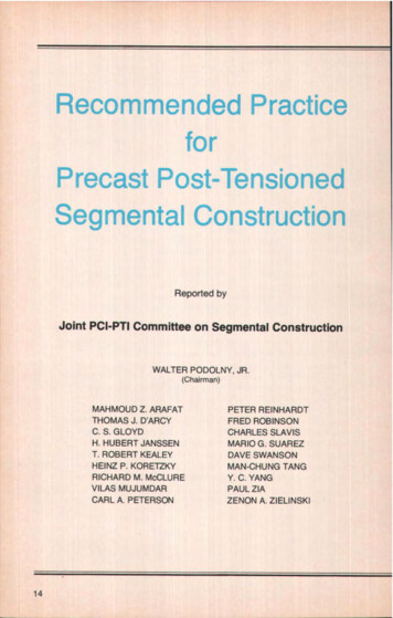
Precast Concrete Constructionpoured on the ground in forms, one on top of the other, as shown in Figure 11. Precastconcrete floor slabs are lifted from the ground up to the final height by lifting cranes.The slab panels are lifted to the top of the column and then moved downwards to thefinal position. Temporary supports are used to keep the slabs in the position until theconnection with the columns has been achieved.In the connections, the steel bars (dowels) that project from the edges of the slabs arewelded to the dowels of the adjacent components and transverse reinforcement barsare installed in place. The connections are then filled with concrete that is poured at thesite.Most buildings of this type have some kind of lateral load-resisting elements, mainlyconsisting of cast-in-place or precast shear walls, etc. In case lateral load-resistingelements (shear walls, etc.) are not present, the lateral load path depends on the abilityof the slab-column connections to transfer bending moments. When the connectionshave been poorly constructed, this is not possible, and the lateral load path maybe incomplete. However, properly constructed slab-column joints are capableof transferring moments as shown by several full-scale vibration tests performed inKyrgyzstan on buildings of this type.Another type of precast system is a slab-column system that uses horizontal prestressing intwo orthogonal directions to achieve continuity. The precast concrete column elementsare 1 to 3 stories high. The reinforced concrete floor slabs fit the clear span betweencolumns. After erecting the slabs and columns of a story, the columns and floor slabsare prestressed by means of prestressing tendons that pass through ducts in the columnsat the floor level and along the gaps left between adjacent slabs (see Figure 12). Afterprestressing, the gaps between the slabs are filled with in situ concrete and the tendonsthen become bonded with the spans. Seismic loads are resisted mainly by the shear walls(precast or cast-in-place) positioned between the columns at appropriate locations. Thistechnology has been used in Yugoslavia during the last 40 years under the proprietaryname, “IMS Building System,” and it can be found in all major Yugoslav cities, includingBelgrade, Novi Sad, Nis, and in other countries, such as Cuba, the Philippines, and Egypt.A typical building under construction is shown in Figure 13.Figure 12: Post-tensioned slab-column connection (WHE Report 68,Serbia and Montenegro)
Precast Concrete ConstructionFigure 13: Assembly of precast columns in progress(WHE Report 68, Serbia and Montenegro)EARTHQUAKE PERFORMANCEThere is a general concern among the earthquake engineering community regardingthe seismic performance of precast construction. Based on experience in pastearthquakes in Eastern European and in Central Asian countries where these systemshave been widely used, it can be concluded that their seismic performance has beenfairly satisfactory. However, when it comes to earthquake performance, the fact isthat “bad news” is more widely publicized than “good news.” For example, the poorperformance of precast frame systems of Seria 111 in the 1988 Spitak (Armenia) (M7.5)earthquake is well known (see Figure 14). However, few engineers are aware of the goodseismic performance (no damage) of several large-panel buildings under constructionat the same site, as shown in Figure 15; these large-panel buildings were of a similar
Lift-slab systems were introduced in the last decade of the Soviet Union (period 1980-1989) in some of the Soviet Republics, including Kyrgyzstan, Tadjikistan, and the Figure 8: A perspective drawing showing cruciform and linear units (WHE Report 33, Kyrgyzstan) Figure 9: Hollow-core precast slab (WHE Report 33, Kyrgyzstan) Precast Concrete Construction 7 Figure 10: A lift-slab building of .