Transcription
Data Acquisition for Geotechnical Analysis inTailing Design and Survey: Approach using CPTTechniqueRodrigo Carrasco1, Michael Dennhardt1 and Beate Lucke21. CDM Smith, Germany2. Lausitzer und Mitteldeutsche Bergbau-Verwaltungsgesellschaft, GermanyABSTRACTThe use of Cone Penetration Tests (CPT), also called “Dutch Cone” - named after its country oforigin, has a long history in civil engineering. It was developed and used in the last decades toprovide raw data for immediate assessment of soil stratigraphy, soil classification, pore waterpressure, and soil strength, among others.Over the years, a large number of correlations for interpretation of soil parameters have beenidentified and are now partly considered to be “standards”. There are relationships which allow theinterpretation of the relative density of granular soils and the consistency of cohesive soils whilstmeasuring the cone penetration resistance of the cone into the ground. Thus, the bearing capacity ofsoils for many design situations may be assessed in a fast and reliable manner from the overseeingengineer.Considering tailing materials (dumps and dams) as being comparable to the natural soft soilsdescribed generally by relative density and consistency, we may draw an analogy between the soilproperties obtained in tailings and those obtained in natural soils with widely-used CPTinterpretation methods. Nevertheless, the peculiarities which may exist from site to site in miningmust be considered.By means of example, a mine site from the current engineering practice in Germany will bepresented emphasizing special points concerning data acquisition using CPT-Testing.INTRODUCTIONA general assessment of the demand for geotechnical expertise for existing tailings in the copperbelt region of North Chiles results in the special need for a fast and reliable field investigation (FI).A fast FI means rapid and safe access to the dam crown and to the tailings storage facility areas,while reliable means accurate data collection of basic parameters on site for further characterizationand dam stability calculations. This may be achieved using the technique described below [8, 9, 10].Many successfully executed tests in mining dumps and tailings demonstrated the viability of CPTtechnique for geotechnical, geochemical and environmental purposes. The performed tests alsooutlined the viability of the method for use in the field of rehabilitation and closing of mines [6, 12].This study to show the potentialities of the use of CPT-Technique in tailing geotechnics, pointingout geotechnical characterization for both tasks design and survey.1
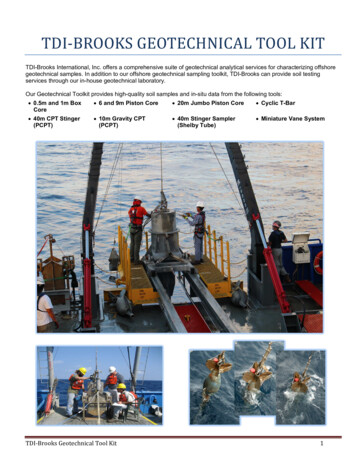
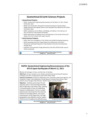
CONE PENETRATION TESTSIn-situ Testing EquipmentCPT-tests are often conducted in mining using a cone apparatus mounted on crawlers with weightsin a range between 15 to 30 tons providing the required reaction to penetration force. Geotechnicaldata is collected at each geotechnical exploration point down to penetration refusal depth. Refusalis typically encountered due to either high tip resistance, high friction along the cone rods or due tohigh CPT rod deviation at depth. Detailed procedures and equipment specifications on CPToperations are provided e.g. in ASTM D5778 [8] or in EN ISO 22476-1 [9] (both Electrical Cone andPiezocone Penetration Testing of Soils).Figure 1 CPT-Sounding with starting point at the top of the dam crown of a tailingFigure 1 schematically depicts the way to start the sounding method [7], whilst Figure 2 shows themobilization of the crawler equipment to the site. Figure 3 shows the measuring cone itself.Figure 2 CPT-Crawler during mobilizationFigure 3 Electrical CPT(U) probeFigures 2 to 3 are courtesy of the Dutch CPT-equipment manufacturer GEOMIL (www.geomilcom).2
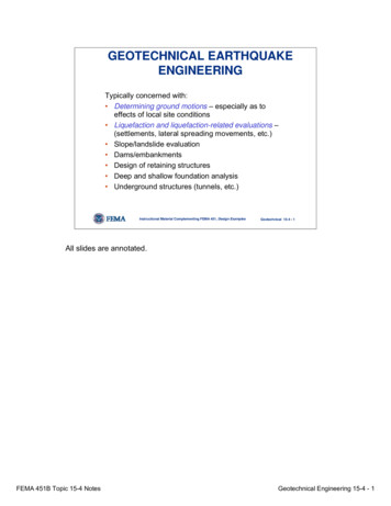
CPT-InterpretationFor soil classification, different CPT based methods have been developed. One of the mostrepresentative methods is the simplified CPT chart method. According to this method thelogarithm of cone tip resistance (qt) is plotted against the friction ratio (FR) to delineate six majorsoil types: gravels, sands, silty sands, sandy silts, silts and clays. Figure 4 showing the relationshipbetween cone penetration resistance (qt) plotted against the friction ratio (FR) indicates thisprocedure (after MAINE, 2007 [5]):Figure 4 Relationship between cone penetration resistance qt against the friction ratio FR [5]The encountered materials are not natural soils but can be classified according to the particle sizetest, e.g. after ASTM D 422 (Particle-Size Analysis of Soils). The main components of theencountered soils belong mostly to the expected fractions (sands, silty sands, sandy silts and silts).Thus, the encountered soils may be classified under the ASTM D2487 (USCS, Unified SoilClassification System [8]).Furthermore, ground engineering properties (such as Cu, ϕ, Eoed, E’ and Dr) may be derived fromthe raw data obtained. Piezo-cones (CPTU) may also be used to assess hydrostatic head,consolidation and permeability characteristics [1, 2, 4, 5].In addition, the seismic Cone Penetration Test (SCPT) is a reliable technique to determine the in situseismic wave velocity giving an indication of ground characteristics such as low strain shearmodulus and Poisson’s ratio.3
CPTu-Interpretation for Granular SoilsAs a guidance for interpretation, the relative density of granular soils may be assessed using therelationship shown in Table 1.Table 1 Cone penetration resistance and relative density of soilsCone penetrationresistanceDesignationRelative densityAngle of internalfrictionIDqt [MPa]ϕ [ ] 2.50 0.15Very loose 302.5 – 7.50.15 – 0.35Loose30 – 357.5 – 15.00.35 – 0.65Medium dense35 – 4015.0 – 25.00.65 – 0.85Dense40 – 45 25.0 0.85Very dense 45CPTu-Interpretation for cohesive soilsAs a guidance for interpretation, the consistency of cohesive soils may be assessed using therelationship shown in Table 2.Table 2 Cone penetration resistance and consistency of soilsCone penetrationresistance,Consistencydesignationqt [MPa]ConsistencyIndex,Undrained shearstrengthCompressivestrength,IcCuUCS [kPa] 0.50Very soft 0.25 20-0.50 – 1.00Soft0.25 – 0.5020 – 40-1.00 – 1.50Firm0.50 – 0.7540 – 7580 – 1501.50 - 2.50Stiff0.75 – 1.0075 – 150150 – 3002.50 – 5.00Very stiff 1.00150 – 300300 – 600 5.00Hard 1.25 300 600Relationship between cone penetration resistance qc (10cm² cone), consistency and undrained shearstrength Cu for cohesive soils (adapted from PRINZ & STRAUSS [3] and EN ISO 14688-2:2004 [10]).4
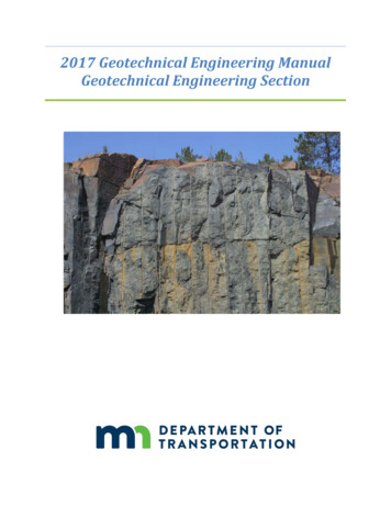
CASE STUDIESIn the region of Lusatia (Lausitz, see Figure 5) in the east of Germany, brown coal was mined inopencast mining since the 19th century. The mining technology scheduled a deep groundwaterlowering to access the coal layers. The overburden was dumped into the dismantled parts of thefield. In the hinterland of the remaining residual holes, which are water-filled after the plannedgroundwater rise, huge and effectively flat inner dump areas with mostly complicated geotechnicalconditions were created.Figure 5 Germany and the Lusatia RegionThus, the dump materials of Lusatia are characterized by water saturated mixed soils with a verylow density of fine and medium sands with low amounts of silts and clays (less than 15% of fines).These soils are subject to soil liquefaction. The main reasons for liquefaction, besides the abovediscussed soil conditions, is understood to be the collapse of the existing grain structure after steady groundwater rise according to the closing of mines schedule and associated initialincrease of pore water overpressure, and sometimes due toadditional exposure to static loads (e.g. additional dumps or earthmoving), and/oradditional exposure to dynamic loads such as heavy equipment induced vibrations, nearbydeep compaction methods (e.g. vibro-displacement) or compaction blasting activity.5
Summarizing, these soils lose their strength almost completely when induced by an initial rise ofpore water overpressures. As a result, in the past and often during the ongoing mining operations,liquefaction occurred involving several million cubic meters of soil, which were thus flowed intoadjacent open spaces [11, 12, 13].In the years since 1990, the geotechnical protection of the slopes for most of the remaining lagoonsin these soils was carried out using deep compaction techniques. In so doing, the risk ofliquefaction for these slopes is now entirely eliminated.For dump areas lying within mining perimeters (inner dumps), it was assumed in the past that anagricultural and forestry use with a groundwater flooring distance of more than three meters isgenerally possible without risk. Since 2009, however, breakings of the surfaces have occurred. Thecause of this can usually not be explained considering only man-made influences.Figure 7 Typical broken terrainThe task of the engineering companies commissioned by the concerned Mining AdministrationCompany (LMBV) is to determine the necessity, nature and extent of pertinent remediationmeasures.The necessary geotechnical model of the dump site massif is based on geological, hydrological, soilphysical and technological data. Part of this data can be determined using the Cone PenetrationTest technique (CPT), measuring pore water pressure, cone resistance, skin friction and relatedfriction ratio.The derivation of soil-index properties and calculation parameters (soil strength andcompressibility) from the obtained data is only possible if sufficient and reliable correlations for therequired parameters are available. These correlations must be obtained by calibrating directinvestigations with undisturbed samples. Hence, the physical laboratory examinations of the soilmust correspond to the aim of the investigations.6
For the assessment of the risk of soil liquefaction of a dump surface, the evaluation of the totalnumber of CPT-Tests performed within the concerned dump region becomes essential. Due to thegenerally used continuous dumping technology for opencast lignite mining by means of conveyorbridges and spreaders, typically you will measure the lower limit of the cone resistance all alongthe vertical sounding length through dump material. For a sandy dump material with a lowerproportion of particles of fines, a cone resistance characteristic close to the lower limit (ch-curve,presented as a green curve in Figure 8) signalizes a high liquefaction sensitivity of the soil.SpreetalFor the Spreetal opencast mine, a representative one among many others, a typical curve wasdetermined which is characterized by the fact that only 5% of the measured values of all CPT testslie below the ch-curve mentioned above. The measured values were previously separated fromvalues for compacted working levels and cohesive areas. The measured values are not connected asusual with lines but rather displayed as individual measuring points [13].Figure 8 Typical Spreetal ch-curve and CPT tests for the low-level areas A, B and CBy comparing the measured values from CPT tests with the above mentioned ch-curve and whileconsidering the friction ratio, it is possible to determine dump regions in which a liquefactionsensitivity is either not given or of lesser extent.7
This task is to be solved on the dump sites of the former opencast mine Spreetal, for example onslopes of low height, but with very low groundwater floor distances at the foot of the embankmentsat the low-level areas A, B and C (see Figure 9). Here, light weight sounding techniques wereapplied to the upper edge of the embankment and the foot of the embankment to underline thedifferentiation of the soils.Figure 9 Soundings CPT 11 and CPT 12 with geotechnical profile 43, showing a clay dump siteThe deviating curves for the friction ratio can be seen in two CPT tests. The localization in the mapshows that both findings are in the area of the "Mittelmassenkippe", where it was assumed thatcohesive soils were dumped. With the high friction ratio (FR) of the probes, which is measured onlyin clay and silt, the evidence is given. For example, a geotechnical profile can be created with theaid of old opencast situations, which clarifies the zone without a liquefaction danger in its positionrelative to the slope as shown in profile 43, Figure 10 [12].Figure 10 Geotechnical profile 43Despite the high groundwater level, the stability of this slope can be demonstrated by means ofproven stability analysis methods and using soil parameters also obtained thanks to correlationsderived from CPT-Tests.8
CONCLUSIONGenerally, CPT-Technique is a fast, reliable, and cost effective means to evaluate the soil conditions(soil profile, geotechnical parameters, groundwater conditions) for preliminary geotechnical design,but also for ground control during construction or for proof of safety after construction and laterduring operations, delivering high quality information from the site. It is suitable for a wide rangeof soils, except for dense gravels, cobbles/boulders and hard rock.For tailing projects in the Andes region, which is often subject to seismic activity, SCPT (seismicCPT) and CPTU (Piezo-CPT for pore pressure measurement) should in any case be used.The main difference between the dumps of the lignite mining in Lusatia and tailings in Chile is thefact that dumps are initially just dumped without any compaction. The compaction (e.g. usingvibro-flotation) follows time after, if required. Tailings by contrast represents a dam embankmentwhich may be engineered during construction.In both cases, the geotechnical investigation is dealing with non-native (remolded) soils. Thus, forevery single site, qualified and experienced personnel in the interpretation of CPT-soundings fortailings should: consider the encountered soil stratigraphy, soil classification and soil properties,identify zones of poor stability, e.g. introducing an adapted ch-curve, after increasingfrequency of soundings in identified liquefaction threatened zones, moreoverconventional soil investigation (laboratory tests to undisturbed samples) should be carriedout as they are necessary for the purpose to confirm or to calibrate existing correlations.The complex evaluation of CPT tests permits conclusions to be drawn about specific dangers, thecauses of which are however to be determined by detailed investigations.ACKNOWLEDGEMENTSThe authors appreciate the support of the Mining Closure Specialist Lausitzer und MitteldeutscheBergbau-Verwaltungsgesellschaft mbH (LMBV) and the CPT-Manufacturer Geomil Equipment B.V. forthe preparation of this paper.NOMENCLATUREqcqtu2afsFR[x]measured cone tip resistance (load/πr²; with r cone radius)corrected total cone resistance, qt qc u2(1-a)measured pore pressurea An/Ac 0,80 (An cross-sectional area of load cell; Ac cross-sectional area of cone)cone sleeve friction (fs load/2πrh; with r cone radius and h friction sleeve high)friction ratio, FR fs/qt (%)Listed references9
REFERENCES[1] Lunne, T., Robertson, P.K. & Powell, J.J.M. (1997). Cone Penetration Testing in Geotechnical Practice,reprinted 2002, Spon Press Editors, London and New York.[2] Look, B. (2007). Handbook of Geotechnical Investigation and Design Tables, 1st Edition, Taylor &Francis, London / Leiden / New York / Philadelphia / Singapore.[3] Prinz, H., Strauss, R. (2011). Engineering Geology, 5th Edition, Springer Editors, Heidelberg.[4] Schnaid, F. (2009). In Situ Testing in Geomechanics, 1st Edition, Taylor & Francis, London.[5] Mayne, P.W. et al. (2007). Cone Penetration Testing, NCHRP Synthesis 368, TransportationResearch Board, Washington D.C.[6] Carrasco, R. (2015). Introducing CPT-XRF Technique into the Chilean Tailings Market, Planta MattaField Test Project, ENAMI/FUGRO, Internal Report, Not Published, Berlin -Planta Matta, Paipote[7] Carrasco, R. (2015). Factual Report, Cone Penetration Testing for Characterization of the RetainingDam of Tailing No. 3, ENAMI, Internal Report, Not Published, Planta Matta, Paipote.[8] ASTM International (2012). Standard Test Method for Electronic Friction Cone and PiezoconePenetration Testing of Soils, ASTM D5778-12, West Conshohocken, PA, USA.[9] DIN (2013). Geotechnical Investigation and Testing – Field Testing – Part 1: Electrical cone andpiezocone penetration test, Euronorm, German version DIN EN ISO 22476-1:2013-10, Beuth VerlagGmbH, Berlin, Germany.[10] CEN (2007). Eurocode 7: Geotechnical design – Part 2: Ground Investigation and Testing, EN1997-2:2007 (E), Beuth Verlag GmbH, Berlin, Germany.[11] LMBV mbH, Universität Karlsruhe, TU Bergakademie Freiberg (1998). Beurteilung derSetzungsfließgefahr und Schutz von Kippen gegen Setzungsfließen[12] Dennhardt, M., Bischof, S (2012). Drucksondierungen bei technologisch unterschiedlich hergestelltenKippen des Braunkohlentagebaues, Beiträge zum Fachkolloquium 4: Bodenverflüssigung bei Kippendes Lausitzer Braunkohlenbergbaus, TU Bergakademie Freiberg, 14./15.06.2012, S. 148-162.[13] Dennhardt, M., Lucke, B., Engelmann, S. (2014). Kenntnisstandanalyse bodenphysikalischerEigenschaften Lausitzer Kippen – Stand der Erfassung und erste Ergebnisse der Datenauswertung,Beiträge zum 2. Kolloquium Bodenverflüssigung bei Kippen des Lausitzer Braunkohlenbergbaus,TU Bergakademie Freiberg, 26./27.06.2014, S. 27-48.10
in a range between 15 to 30 tons providing the required reaction to penetration force Geotechnical . data is collected at each geotechnical exploration down pointto penetration refusal depth. Refusal is typically encountered due to either high tip resistance, high friction along the cone rods or due to high CPT rod deviation at depth.