Transcription
UPTEC IT10 010Examensarbete 30 hpMars 2010Pilot Project for Model BasedTesting using Conformiq QtronicRobin SvingPeter Öman
AbstractPilot Project for Model Based Testing using ConformiqQtronicRobin Sving & Peter ÖmanTeknisk- naturvetenskaplig orietLägerhyddsvägen 1Hus 4, Plan 0Postadress:Box 536751 21 UppsalaTelefon:018 – 471 30 03Telefax:018 – 471 30 00Hemsida:http://www.teknat.uu.se/studentSoftware testing measures quality in software systems and the time for testing isheavily affected by the system complexity. Even small changes to a complex systemmay require large amounts of time and effort to verify quality, so in order to enablefaster testing, test automation can be favourable to manual testing.One technique for test automation is model based testing (MBT). MBT is a techniquebased on black box testing, which uses models of a system, called design models, at ahigh abstraction level to generate test cases. This abstraction is achieved by creatingthe models without examining the implementation of the system.This thesis explores the possibility of applying MBT at a large telecom company, usingthe Conformiq Qtronic testing tool, and analyses difficulties during the process.Due to the system documentation not being on a level of detail appropriate forcreating a design model from, the model was instead created from a developmentmodel. The model was used to generate test cases automatically. Using a custom“scripting backend”, Qtronic was able to render these test cases into executablescripts.Mismatches in both the languages and structures of the Qtronic toolset and thetelecom company's system required some makeshift solutions.This thesis shows that it is possible to use MBT efficiently for software testing; MBTgrants more comprehensive test cases, reduced test generation time, and requiresless complexity than manual testing.Handledare: Christofer JanstålÄmnesgranskare: Justin PearsonExaminator: Anders JanssonISSN: 1401-5749, UPTEC IT10 010Tryckt av: Reprocentralen ITC
SammanfattningMjukvarutestning utvärderar kvalitet i ett mjukvarusystem och testningstiderpåverkas starkt av systemets komplexitet. Även vid små systemuppdateringar kan detkrävas enorm tid och ansträngning för att kontrollera kvaliteten, så för att snabba upptestningsprocessen kan automatiserad testning vara fördelaktigt jämfört med manuelltestning.En bra teknik för testautomatisering är modellbaserad testning (MBT). MBT är en”black-box”-testningsteknik, som använder sig av systemmodeller på en högabstraktionsnivå, så kallade designmodeller, för att generera testfall. Abstraktionenåstadkoms genom att modellerna skapas från systemdokumentation i stället försystemimplementation.Denna rapport undersöker möjligheten att anpassa MBT till ett stort telekom-företaggenom att använda testningsverktyget Qtronic från företaget Conformiq , samtanalyserar svårigheterna för denna process.På grund av att systemdokumentationen inte låg på en passande nivå för att skapadesignmodellen ifrån, skapades istället modellen från en utvecklingsmodell.Modellen kunde sedan användas för att automatiskt generera en svit med testfall. Medhjälp av ett anpassat ”scripting backend” kunde Qtronic rendera dessa testfall tillkörbara script.På grund av språk- och stukturskillnader mellan Qtronic och de program som användspå telekomföretaget krävdes ett antal skräddarsydda speciallösningar.Denna rapport visar att det är möjligt att använda MBT effektivt förmjukvarutestning; det ger mer uttömmande testfall, reducerar tidsåtgången förtestfallsgenerering, samtidigt som det är mindre komplext än att arbeta manuellt.
AcknowledgementsThe authors of this report would like to thank the following people at the largetelecom company where the thesis was done (in alphabetical order):Lars Hennert, Roger Holmberg, Christofer Janstål, Leif Jonsson, Sergey Lysak,Fredrik Weimer and many more.From the universities:Uppsala University – Justin PearsonLuleå Technical University – Josef HallbergAlso, from Conformiq :Athanasios Karapantelakis and Michael Lidén
Table of Contents1 Introduction. 11.1 Background . 11.2 Problem definition . 11.3 Goals . 21.4 Limitations . 22 Technical background . 32.1 Mobile Telecommunication Network . 32.1.1 Radio Access Network . 32.1.2 RBS Systems . 42.1.3 Blocks and signals . 52.2 Development of large systems. 52.2.1 Development framework . 52.2.2 Model based development . 62.2.3 Using Development Tools . 62.2.4 Development at the LTC . 62.3 Quality assurance of large systems . 72.3.1 Scope of testing . 72.3.2 Testing Process . 92.3.3 Coverage . 102.3.4 Current testing at the LTC . 123 Model based testing . 133.1 Understanding model based testing . 133.1.1 History . 133.1.2 Approaches. 133.1.3 Abstraction . 143.2 Unified Modelling Language . 143.2.1 UML state machines . 153.2.2 Sequence diagrams . 153.2.3 Use case diagram . 153.2.4 Class diagram . 163.3 The MBT process . 163.3.1 Creating a model . 163.3.2 Generate tests cases . 173.3.3 Make the tests executable . 183.3.4 Analyse the executed tests . 193.4 Changes between MBT and manual testing . 193.4.1 Increased test coverage . 193.4.2 Test automation . 203.4.3 MBT experiences . 204 Conformiq Qtronic . 224.1 The Qtronic suite . 224.1.1 Qtronic Computational Server . 224.1.2 Client . 234.1.3 Conformiq Modeler . 244.2 Models in Qtronic. 244.2.1 Textual notation . 254.2.2 Graphical notation . 26
4.2.3 Test case control using QML functions . 294.3 Usability. 314.3.1 Testing limitations . 314.3.2 Test configuration . 314.3.3 Testing approaches . 324.4 Qtronic scripting backend . 334.4.1 Using a bundled scripter . 334.4.2 Creating a new scripter . 334.4.3 Scripting with Qtronic functions . 345 Methodology . 375.1 Before starting a pilot project . 375.1.1 Working with simple models . 375.1.2 Working with big models . 375.2 Working on a pilot project . 395.2.1 How to choose a pilot project . 395.2.2 Before starting to model . 395.3 Backend structuring . 405.3.1 Scripting to Goat . 405.3.2 Step-by-step scripting . 416 Implementation . 426.1 Model . 426.1.1 Choice of functionality . 426.1.2 Identify relevant ports and signals . 436.1.3 Identifying scenarios . 446.1.4 Modelling the scenarios . 466.2 Scripting backend . 466.2.1 Implementing Scripting Backend Configurations . 466.2.2 Implementation of ScriptBackend methods . 476.3 Problems . 506.3.1 Model difficulties . 506.3.2 Scripter limitations. 516.3.3 Goat issues . 526.3.4 Error handling and Qtronic Algorithmic Options. 537 Results . 547.1 The pilot project . 547.1.1 The QML model . 547.1.2 The Goat script backend . 547.2 Test suite . 577.2.1 Test execution. 577.2.2 System faults . 577.3 Time . 577.3.1 Qtronic education . 577.3.2 Approximate total time spent . 587.4 Lessons learned . 598 Discussion . 608.1 Analysis . 608.1.1 A working proof-of-concept . 608.1.2 Testing the SUT . 608.1.3 Qtronic test case selection . 61
8.2 Conclusions . 618.2.1 Speed . 618.2.2 Simplicity. 618.2.3 Flexibility . 628.3 Future work . 628.3.1 Recommendation for the LTC . 628.3.2 Recommendations for Conformiq . 63References . 66Appendix I - Table of Abbreviations . AAppendix II - Table of Terminology . BAppendix III - Qtronic Client. CAppendix IV - Conformiq Modeler . DAppendix V - Project plan . E
List of TablesTable #Table contentsSectionTable 1Test coverage from white box testing2.3.3Table 2Test coverage added by using MBT3.4.1Table 3The five states of a graphical state machine4.2.2Table 4The seven functions that make up the structure of ascripting backend4.4.3Table 5Step-by-step structure for model creation5.2.2Table 6Step-by-step structure for scripter creation5.3.2Table 7Pilot project ports and their corresponding signals6.1.2Table 8Grouping of possible responses received during asystem reconfiguration6.1.3Table 9Table of AbbreviationAppendix ITable 10Table of TerminologyAppendix IITable 11Project plan for pilot project thesisAppendix V
1 Introduction1.1 BackgroundWithin software development, testing is an integral part. Currently, testing is oftendone by manually finding and designing single test cases and then writing test scriptsfor these cases. This process is both time consuming and error prone[3][5].In order to develop large and complex software systems, developers need to work at ahigher abstraction level than today. Shorter lead times and the need for highmaintainability are two of the key drivers for the evolution of the softwaredevelopment process.To leverage the increased complexity, model based development has started to get ahold in the industry[3], and there are lots of different tools for this type ofdevelopment currently in use.The next generation testing tools use a testing method called model based testing(MBT) to raise the level of abstraction for the developer. By using a higherabstraction level when testing a system, productivity can be increased andinconsistencies eliminated while providing optimisations for the whole system.1.2 Problem definitionThis thesis will be carried out at a Large Telecom Company, hereafter referred to asLTC. It will focus on an evaluation of the next generation MBT tools fromConformiq seen from the perspective of a user of their services. The thesis will alsodemonstrate the required changes the LTC needs to adopt, in order to transition toMBT from traditional testing methods.Qtronic is a tool from Conformiq used for automated test case generation and isdriven by design models. This means that Qtronic can generate tests for animplemented system, referred to as the system under test (SUT), automatically whengiven a model of the SUT as input. The design model is a description of the intendedbehaviour, i.e. the functionality, of the system on a high level of abstraction, whichmeans that the SUT is tested on its expected behaviour, and not its implemented code.Qtronic can automatically render test cases into a number of scripting languages,using so called scripting backends, which work as a translation tool between testcases and executable test scripts. It is bundled with backends for some standardisedscript languages, as well as tools to create new backends. The LTC uses Goat, aproprietary scripting language, which requires that a Goat backend is created.The thisis includes tool analysis and platform integration where usability,productivity and suitability of the Qtronic suite play a vital part.1 (67)
1.3 GoalsThere are three main goals of the thesis: Create a model of a system based on a requirements specificationprovided by the test environment used by the LTC. This model shouldbe a proof-of-concept that an abstract design model can be used asinput for Qtronic. Develop a scripting backend for Qtronic. Provide an evaluation of Conformiq Qtronic. The evaluation shouldanalyse its suitability for the LTC environment.1.4 LimitationsThese are the limitations for the thesis: The design model will only work as a proof-of-concept that a systemcan be correctly represented in Qtronic. It will not be a fullrepresentation of the system. The evaluation of Qtronic will not be a test of the program itself.Instead it will be a focus on how well Qtronic performs in the LTCenvironment. The evaluation will be done on a Linux SUSE operating system usinga Qtronic plug-in to the development tool Eclipse. No other Qtronicenvironments shall be evaluated. The models will be created manually. No program for automaticgeneration of the models will be used or developed.2 (67)
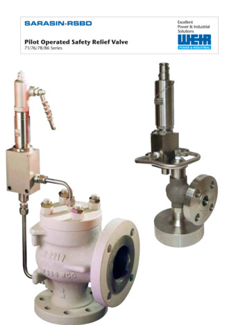
2 Technical backgroundThis section will cover the background needed to understand how mobiletelecommunication networks (MTCN) work, how to support creation of systems ofimmense sizes, and the principles of assuring quality during its development.2.1 Mobile Telecommunication NetworkThe core network is a network of connected nodes and links and is the basis for wirebased communication. It can be accessed by wireless communication from outside ofthe wired network using the MTCN. This infrastructure serves as the backbone forallowing mobile devices worldwide to connect to each other.2.1.1 Radio Access NetworkThe MTCN consists of a number of Radio Access Networks (RAN). RAN is acollective name for all networks using a certain standard for mobile communication.There are a number of these standards, including the most common GSM and UMTS(3G) standards.The reason multiple standards are used is because the newer generations of mobilephones require different techniques and higher bandwidth to be able to support newfeatures. For example, when the second generation GSM network was created therewere no requirements for high data rates since the only information that would besent was voice and text (and later also web site data, using WAP). A newer mobilesystem needs much higher data rates to support more recent services, such asconference calling, web browsing, video and other multimedia streaming.Different types of standard MTCNs use different techniques and terminologies intheir structures. This thesis focuses mainly on WCDMA networks, one of thecommonly used standards in 3G networks, and the subsequent sections are specificfor the WCDMA RAN architecture.Radio Network ControllerThe Radio Network Controllers (RNC) are nodes within a RAN that are used tofacilitate communication between the RAN and the core network. Among otherthings an RNC handles the traffic load distribution and quality assurance as well ascommunicating updates and settings changes to its connected Radio Base Stations(RBS).3 (67)
Figure 1. The WCDMA consists of RNCs and RBSs.Radio Base StationThe RBS serves as the entry points to the RAN for the User Equipment (UE) and isthe node responsible for handling the radio transmission to and from the UE. UE canrepresent virtually any device communicating wirelessly using a recognisablestandard. Commonly used devices are mobile phones, laptops with modems or PDAs.2.1.2 RBS SystemsAn RBS can come in hundreds of different configurations and sizes. Determiningfactors can be the number of UE it is meant to control or the range of the signals itsends.The RBS systems are divided into several subsystems, i.e. smaller systems forhandling different functionalities within the RBS. The subsystems can communicatewith each other through something called OSE-signals. This thesis will be carried outin the Channel Control (CHC) subsystem, where different types of channels likecommon channels and dedicated channels are managed.4 (67)
2.1.3 Blocks and signalsEach subsystem is divided into software blocks. All of the blocks in the RBSs havemultiple signals sent constantly, trying to interact with the rest of the system. A signalin CHC can, for example, be setup or reconfiguration requests for a channel, confirmand reject signals, or indication signals.Signals can be very simple, containing only an integer, or even a void (a signal withno values), or very complex, with data structures within data structures. Somestructures can have more than 200 parameter fields.2.2 Development of large systemsWhen developing small systems, it is often quite simple to keep track of the differentparts that make up the system and the programming can be performed in a lessstructured way. With increased complexity of large scale systems a more structuredway of working becomes necessary. Companies with many employees working onthe same system may find that a structured development process helps to avoidmistakes and problems.2.2.1 Development frameworkA software development framework contains principles for structuring and planning,as well as approaches to coding a system. There are several different softwaredevelopment approaches, each having advantages and disadvantages.The LTC uses a software development framework similar to Rational Unified Process(RUP), which was developed by IBM Rational Software in 1998[1][2]. It is based onRationals’ Six Best Practices: Develop iteratively Manage requirements Use component based development Model visually Control changes with version handling tools Verify quality by continuous testingThis approach had some radical ideas when it arrived, for example that complexsystems should be modelled as a number of interconnected, smaller subsystems. Thisidea is known as component based development or, more informally, “divide andconquer”.5 (67)
2.2.2 Model based developmentRUP also implements the dynamic view, describing how all the blocks communicatewith each other using sequences and state charts. This is known as a model basedstructure. It models the behaviour of a system, representing the different systemcomponents and transitions in model diagrams, while ignoring the internalfunctionality of the components.There are many types of models than can describe the behaviour of a system. Themost common are based on Unified Modeling Language (UML) state machines (seesection 3.2.1).2.2.3 Using Development ToolsIn order to simplify using a development framework there are a large number of toolsadapted for use within a framework. These tools perform a wide variety of tasks.There are tools for version handling, project management, coding, for graphicallyvisualising models and for testing. A tool may serve a specific purpose, for exampleClearCase or Subversion for version handling, while other programs like Eclipse orMicrosoft Visual Studio may be used for multiple functionalities.Many large software developing companies will not just use one tool to cover all oftheir needs. For example, the LTC uses ClearCase for version handling and RationalRoseRT, a proprietary software suite, for model based development, graphicalvisualisation, coding and compilation.2.2.4 Development at the LTCAs mentioned earlier the LTC uses a development framework similar to RUP, whichmeans that they adhere to many of the six best practices. They rely heavily on versionhandling using ClearCase, and do extensive quality assurance on their code.It also means that their development is component-based and that the system ismodelled visually in a set of different UML diagrams. In Rational RoseRT (seesection 2.2.3), the components are called capsules and can contain UML statediagrams and C code. Successively, the state machines together with the C -codeare used to generate executable machine code to create the actual system. Capsulescan contain other capsules, and the complexity of the system means that severallayers can be used for a single functionality.Capsules communicate with each other using a set of standardised signals, which canbe of different complexity. The structures of the signals that are sent between thecapsules are not necessarily the same as those sent between subsystems (see section2.1.2).6 (67)
2.3 Quality assurance of large systemsWhile creating a large software system one has to make sure that the reliability of theproduct is guaranteed. In order to find system errors and correct them a number ofrigorous tests upon the system is needed. In other words, testing is a process ofvalidating that the software performs as expected.Even though the underlying purpose of a software test is the same, tests can beperformed in a number of ways.2.3.1 Scope of testingWhen creating tests for a system, the extent of the tests can be determined by threemain factors [3][4]: scale, characteristics and the amount of internal knowledge.Figure 2. The extent of tests determined by scale, characteristics, and systemknowledge.7 (67)
ScaleThe scale of the test determines on what level in the system the test is beingperformed. The smallest part of the system is referred to as a unit. This can be asingle method or class within the system. Since units are small, and often very simplethe unit tests are often done by the programmers themselves during theimplementation process. If a faulty unit is implemented, the time and effort to find itsfault will increase with each level, which is why unit testing is important.The next level on the scale hierarchy is the component, which consists of severalunits. The tests carried out on the component level consist of testing each componentseparately. At this level it is less likely that the testing is made by the programmer.The reason behind this is the increased amount of time required to do more thoroughtests due to the magnitude and complexity of the components.The third level of the scale is integration testing. This is the testing of integrationbetween two or more components communicating with each other. At this level it willnot be possible to locate a fault within a component, which means that all componentsshould have been tested thoroughly. This is time demanding and should, just likecomponent testing, be done by dedicated testers.The final testing level is system testing, which is performed on the entire system. Thistest makes sure that all integrations between the subsystems are working as intended.The system should at this point be free of any major errors, since an error at this levelwould require a lot more effort to find, diagnose and repair.CharacteristicsThe characteristics of the tests determine the types of errors the tester is looking for.If a test is meant to find erroneous behaviour of the system functions when theprovided input is correct the characteristics of the tests are called functional orbehavioural testing. This type of test is done to find errors in the code or design of thesystem under test (SUT).If a test on the other hand is meant to analyse error-handling, due to faulty inputvalues, broken hardware or network failure, the characteristics is called robustnesstesting. This type of testing ignores whether the coding is correct or not and insteadfocuses on how the SUT handles unforeseen events.In many systems performance is just as important as function. When put under heavystress a system should not only continue working as intended, but also ensure thatcomputations are performed within reasonable time. This is tested by simulating anenvironment which causes heavy load (like multiple users or intense calculations).This type of testing is known as stress testing.The final characteristics of testing is the usability testing. This is done to test the easeof use of the user interface, for example by observing users to see if they might beconfused or make mistakes while using the software.8 (67)
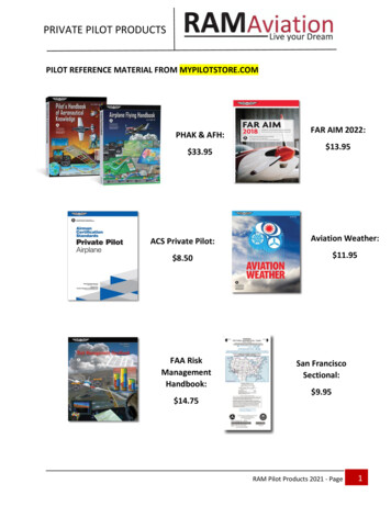
Internal information (The box approach)The final principle of testing describes the amount of internal information of an SUT.There are three levels to describe this: the black box, the white box and the grey box.When testing using a black box approach nothing is known of the internal design ofthe SUT. The only information available is the system requirements, i.e. the possibleinput values and expected output values.Figure 3. In black box testing, nothing is known of the internals of the system.The opposite of the black box approach is the white box approach, where the internaldesign of the system is described in full extent. The effect of this is that a test can bemore thorough than in a black box test; the tester can create a test where all functionsand all units are accessed at least once before finishing or a test where all booleanconditions are tried out with both true and false.The grey box testing is a mix between the black box and white box approach. Thisapproach describes parts of the internal design and functionality.Most tests are derived from a black box approach. Even software developers whowant to create tests from their own system will, even though they are aware of theinternal structure, think of the system as a black box. They only care whether thereceived output corresponds correctly to the given input.2.3.2 Testing ProcessThe process of testing a system can be done in many different ways, but in mostcases, regardless of which is used, there is a certain methodology that will be applied.Finding test casesThe first step is to find test cases that cover the system requirements. A test case isdefined by a con
Conformiq seen from the perspective of a user of their services. The thesis will also demonstrate the required changes the LTC needs to adopt, in order to transition to MBT from traditional testing methods. Qtronic is a tool from Conformiq used for automated test case generation and is driven by design models. This means that Qtronic can .