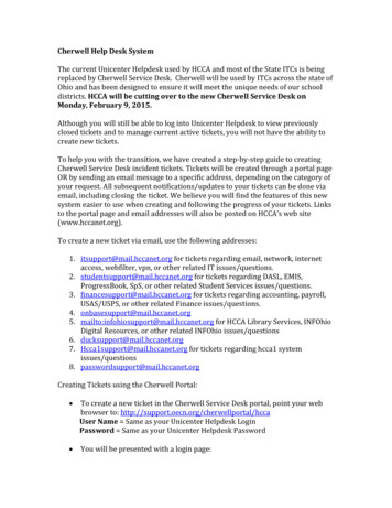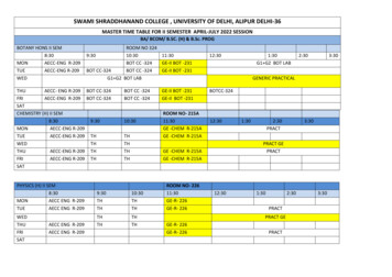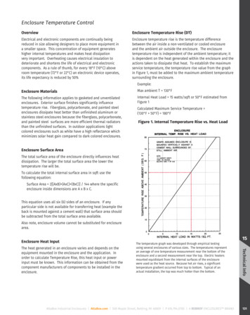
Transcription
INSTALLATION ANDMAINTENANCE MANUALITCS ENCLOSUREALUMINIUM ENCLOSURESFOR INTELLIGENT TRAFFICCONTROL SYSTEMSLogix ITCS 001 – 08/09/2020
Revision historyRevisionStatusPrepared byChecked byDateADraftC ShortT Hamilton28/08/20BRevisedC ShortT Hamilton07/09/20CRevisedC ShortT Hamilton25/09/20ApprovalNamePositionSignatureTony HamiltonDraft28/08/201 DISCLAIMERThis document is for the use of installation and maintenance, both general servicingand the break-fix process for the Logix Engineering ITCS Enclosure.Model numbers ITCS 180906 – Standard Range ITS Cabinet ITDS 180906/AC20 – Extended Range ITS CabinetInformation contained in this document is for use by authorised electrical or technical persons, who have thenecessary mandatory qualifications, to either install, service or replace various components of the ITCS Enclosure.This document is not intended for use by any person who does not hold the necessary industry qualifications toundertake work or access electrical systems.Failure to observe industry-standard safety precautions may result in serious injury to persons either performingthe works or any other person who comes into contact with the enclosure or its contents, during or following installation,servicing or repair by unqualified or unauthorised persons.Logix Engineering does not accept any liability if the transportation and lifting of concrete plinths and or enclosuresdoes not meet minimum requirements as identified in the safety and lifting processes section of this document.2Installation & Maintenance Manual ITCS Enclosure
CONTENTS1Disclaimer22Introduction43Primary contact48Electrical108.1 General description108.1.1 Mains connection108.1.2 Electrical distribution board118.2 Telecommunications connections114 Standards accreditationand test certification55 Transport department type approvalsand compliance58.3 Labelling126 ITCS enclosure – general description68.4 Enclosure fan units126.1 Dimensions68.5 Filters236.2 Construction68.6 Circuit diagrams126.3 Basic enclosure weight78.6.1 Standard general enclosure126.4 Enclosure access7136.5 Door management locking bars78.6.2 Victorian Roadscircuit diagramInstallation88.6.3 QLD Department MainRoads circuit diagram137.1 General87.2 Site requirements7Routine maintenance1489.1 6 month – general maintenance147.3 Concrete plinth89.2 12 month – general maintenance157.4 Standard plinth layout910 General maintenance177.5 Lifting of concrete plinth910.1 Safety note177.6 Securing enclosure to plinth910.2 Minimum test equipmentto perform works177.7 Cable access107.8 Vermin and moisture precautions10911 Recommended spares1811.1 Enclosure1811.2 Electrical1812 Abbreviations/terminology19ITCS 0013
2 INTRODUCTIONLogix Engineering manufactures a series of ITCS cabinets for the support of Intelligent TransportationIndustry (ITS) technology applications and platforms, for use in transportation infrastructure acrossAustralia and New Zealand.The Logix ITCS Enclosure is designed and manufacturedto comply with a variety of government departmentalspecifications identified but not limited to in section 3.1 ofthis document. With the added ability to modify enclosuresto suit site-specific project requirementswhile maintaining compliance.ITCS enclosures provide a secure, safe, environmentallycompliant and flexible housing to accommodate variouselectronic devices and software that support IntelligentTransportation Systems for all types of infrastructure.ITS systems and technologies include but arenot limited to: CCTV Systems Electronic Signs Radar Central Control Systems Vehicle Detection Systems Traffic Control & Monitoring Software Integrated Tunnel Control SystemsAll of which are supported by power regulationand distribution wiring systems which can bemodified to suit specific project requirementswithin the Logix ITCS enclosure.3 PRIMARY CONTACTTONY HAMILTONLogix Engineering28 Boron St, Sumner Park, Brisbane QLD 4074 AustraliaP (07) 3376 9436 M 0434 034 703 E tony@logixeng.com.aulogixeng.com.au4Installation & Maintenance Manual ITCS Enclosure
4 STANDARDS ACCREDITATION AND TEST CERTIFICATIONThe enclosure is designed and manufactured to comply with the following specifications:Certificate RegisterType of Test / RequirementStandardComplianceTesting AuthorityDegree of protectionAS60529-2004NE09/0023SIMTARSMechanical load testAS2317-1998NE09/0005SIMTARSMechanical lifting testAS62208-2006NE09/0005SIMTARSDegree of protection (1)AS60529-2004NE11/0004SIMTARSDegree of protection 53-TRP-600858-0VIPACWind loadingAS 1170.2 201118/13KJB ENGINEERINGMechanical loadingAS 1170.1 201118/13KJB ENGINEERINGGalvanic reactiondissimilar materialsAS4036 - 200618/13KJB ENGINEERINGAS2331.3.1HLC/2012/283HRL TECHNOLOGYSimulated solar radiation testCorrosion and related property –neutral salt spray test5 TRANSPORT DEPARTMENT TYPEAPPROVALS AND COMPLIANCEQUEENSLAND DEPARTMENTOF MAIN ROADS MRTS 226 Telecommunications Field CabinetsDEPARTMENT OF PLANNINGTRANSPORTS AND INFRASTRUCTURE(DPTI) – SA Certificate Number 13-094 ITS and Electrical ITCS 180906 Standard Range ITS Cabinet ITDS 180906/AC20 Extended Range ITS CabinetVICTORIAN DEPARTMENT OF MAIN ROADS PA 030 239Certificate of Type Approval Number TCS 061 ITS Field CabinetsROADS AND MARITIME SERVICES – NSW Complies with DPTI specification 265DEPARTMENT OF MAIN ROADS WA Complies with drawings 201948 – 3406 and 201948 – 3321NEW ZEALAND TRANSPORTAUTHORITY - NZTA Complies with ITS-02-04TSI-SP-012 General Requirements for RoadsideEquipment HousingITCS 0015
6 ITCS ENCLOSURE GENERAL DESCRIPTIONA standard enclosure comprises a centre frame built to accommodate standard RU type rackmeasurements which allow for the majority of electronic hardware to be secured using standardCage Nut & Bolt or Rack Studs.The internal frame can also be modified to suit a “Non-Standard “item of equipment or can be split into a varietyof interior configurations while maintaining its fundamental characteristics and compliance.6.1 DIMENSIONSThe standard ITCS Enclosure is available in 3 configurations as shown belowStandard ITCS Enclosure DimensionsHeight (mm)*Width (mm)*Depth (mm)*Overall Height (mm)24 RU1400755/900620162530 RU1600755/900620182537 RU1800755/9006202025*The dimensions indicated are of the enclosure frame only. Excludes plinth, roof height and roof overhang.ITCS ENCLOSUREAn enclosure consistsof 4 doors: Front andrear with side openings.This all-round accessallowing all internalareas of the enclosure forequipment maintenance.6.2 CONSTRUCTIONThe ITCS enclosure is manufactured from powder-coated 2.5mm marine-grade aluminium alloy which allows for a strong,flexible enclosure with excellent heat management properties which allows for low internal temperature rise.6Installation & Maintenance Manual ITCS Enclosure
6.3 BASIC ENCLOSURE WEIGHTThe ITCS enclosure base weight is 200 Kgand is lifted into place via the installation of4 lift eye bolts supplied with each cabinet.The Safe Working Load (SWL) rating for each bolt is230kg and have been tested in accordance with: AS 2317-1998 “Collared Lifting Eyebolt” AS 62208-2006, Clause 9.4 “Lifting”Only Logix supplied lifting bolts are to be used forlifting the enclosure to ensure enclosure warrantiesare maintained. Other forms of securing bolts usedwhen lifting enclosures will void all warranties.The Logix supplied lifting eye bolts are explicitlyrated for the Logic ITCS Enclosure not to be usedfor any other purpose.Were project-specific requirements to lift an enclosureare required using an alternative method, then LogixEngineering must be consulted to obtain prior approvals.Note: Enclosure lifting bolts are designed to be left inthe enclosure roof and are not to be removed.See Figure 2: Lifting bolt locations6.4 ENCLOSURE ACCESSFront and rear doors are fitted with a 3-pointlocking system: Centre, Top and Bottom withthe standard Department of Main Roads key.However, cabinets can be keyed with a projectspecific key if the requirements call for it.Standard Restricted Key Codes are as per below Queensland Transport and Mani roads QTMR – 92390 Roads and Maritime Services NSW – TL493 VicRoads – BiLock DPTI SA – 92190 Main Roads Western Australia – 247EFront and rear door keyed locksSide doors are locked by an internal locking system,which can only be accessed by opening the front reardoor. This type of locking allows for greater securityfrom unauthorised entry.6.5 DOOR MANAGEMENT LOCKING BARSLeft and right side door inside lockEach enclosure to door has a door managementlocking bar fitted to the base of the opening toensure the door does not close without control.These bars lock ion the open position and can only bereleased by operating the latching mechanism.ITCS 0017
7 INSTALLATION7.1 GENERALThe recommended installation technique of an enclosure is with the use of a preformed concrete plinth.The use of a plinth allows for a stable, secure cable access entry points to be above the surrounding ground levels, therebypreventing water ingress into the base of the equipment.Previously installed conduits for Electrical and Communications cabling are positioned in the centre of the concrete base,to allow for ease of access up into the bottom of the enclosure via the transition plates into the chassis.7.2 SITE REQUIREMENTSIt is recommended each enclosure location is a flat area of at least 3mts by 3mts square comprisingof compacted road base or equivalent.A compacted firm base will allow for the installation of the plinth on a stable platform which will support the enclosure.On some sites, a poured concrete surround may be installed to provide further stability and durability of the platform asa result of weather conditions.7.3 CONCRETE PLINTHThe plinth is composition uses steel reinforced concrete which can, if required, be constructed on-site.However, Logix recommends the standard manufactured plinth is used to ensure no installation issues with the alignmentand securing of each enclosure.General installation positioning: before the concrete surround installation.8Installation & Maintenance Manual ITCS Enclosure
7.4 STANDARD PLINTH LAYOUT7.5 LIFTING OF CONCRETE PLINTHThe general transportation of a concrete plinth to a site is on pallets.Once onsite, pallets can be relocated using a suitable lifting device suchas a forklift or machine mounted crane, which can provide safe liftingloads rated at a minimum of 600 kgs.Each preformed concrete plinth has lifting points cast into each slab at the time ofmanufacture. These lifting points will accept project approved and certified lift eyeor ring bolts with M12 shanks and should be used in association with tested andapproved chains or slings for these weights.A typical Lifting method is shown below, onto a previously prepared location.The use of stacker bars under each plinth is not mandatory, but may in someinstances aid with the installation of the plinth.7.6 SECURING ENCLOSURE TO PLINTHEnclosures are secured to the plinth by the fitting of 4 x M12 Stainless Bolts including flat washers(not supplied as part of the cabinet).Access to each fixing location is by removing the aluminium base cover plates cable entry area and locating bolt holesin each of the corners.If the cabinet has been positioned correctly, then all bolts holes will line up with the pre-cast ferrules in the concreteplinth. Installed bolts should then be tightened with the correct socket spanner to provide a secure fixing of the enclosure.ITCS 0019
7.7 CABLE ACCESSCable access is via the three aluminium plates in the bottom of the enclosure.These plates are removed by removing hold down screws or the opening the toggle handle at each end of the plates(depending on the model) and removing each one in turn to allow access to the previously installed conduits and drawsropes. Cable access glands are installed in each plate ready for the installation of cables.Aluminium base plates: fixed into positionwith cable accessInstallation note: Although enclosures allow for cable installation across all three plates in the cabinet base, it isrecommended cables be split into types as can be seen in the above picture. This allows easier access when installingadditional cables and maintenance during the lifetime of the enclosure.7.8 VERMIN AND MOISTURE PRECAUTIONSAccess to the interior is restricted, by the use of a sealed cable access area in the enclosure base.Provided the Aluminium cable plates are secured correctly, then the prevention of rats and mice gaining accessto the cabinet is significantly reduced.As part of the installation process, the restriction of Ant and Insect the infestation is achieved by the installationof a silicone bead. This Silicon bead is to be run between the base of the enclosure and concrete plinth. This is tobe completed after the cabinet is secured to the plinth.8 ELECTRICAL8.1 GENERAL DESCRIPTIONThe electrical and communications layout of the ITCS enclosure utilises standard industry componentswhich are available from most electrical industry wholesalers.This allows for a flexible and optimised enclosure that will support a wide range of electronic switching and controlequipment to be accommodated in both a functional and accessible design.8.1.1 MAINS CONNECTIONSingle or three-phase (Model Dependant) incoming mainsconnection is terminated in the Incoming Mains TerminationEnclosure, as shown in pictures to the right.The enclosure is accessed via the side door which canonly be unlocked by the opening of the front and reardoor. This adds to the overall security of the enclosure.Mains termination boxwith cover10Installation & Maintenance Manual ITCS EnclosureMains termination boxwithout cover
8.1.2 ELECTRICAL DISTRIBUTION BOARDThis internal electrical board comprises of the following Distribution Block which comprises of (Main Active, Main Neutral, Main Earth and Main Earth Neutral Link) Main Switch (Fuse, MCB or Isolator). Surge Protection Surge DiverterThe cabinet provides for a standard electrical distribution centre however can be modified to suit project requirements,for example – the provision of a UPS and other bespoke power distribution systems. The power distribution board canbe installed either as a top-mounted unit or at the base of the cabinet, as shown in the pictures below.Top mounted distribution boardBottom mounted distribution boardAll connections use industry-standard terminations and are only accessible by the removal of the protective plastic covers.Any cover should only be removed by a qualified electrical person and terminations checked for tightness during the 12monthly maintenance cycle.Distribution board with cover fittedDistribution board without cover fitted8.2 TELECOMMUNICATIONS CONNECTIONSA combination of Telecommunications cabling can be installed in the enclosure utilising thestandard 19” frame that can support copper patch panels of all grades, including fibre opticpanels and frames for networking applications.Fibre optic and copper termination panels and frames can be installed in the 19” rack using industry standard fixings.ITCS 00111
8.3 LABELLINGEnclosure labelling is in accordance with AustralianStandards for electrical cabinets and devices.All labelling should be checked at every inspectionperiod – 6 and 12 months.8.4 ENCLOSURE FAN UNITSFan units are mounted in both side doors to providea high airflow rate when the internal enclosuretemperature exceeds the required temperature pointas set when first installed.It should be noted the Logix ITS enclosure is suitable for usein locations that do not permit fans for airflow. The enclosureenvironmental compliance is identified in this document in thesection Certification Register.8.4: Enclosure fan unit8.5 FILTERSEnclosure filters can be replaced as required dependingon local climatic conditions.Filters can be accessed using an 8mm square key as shown above.8.6 CIRCUIT DIAGRAMS8.6.1 STANDARD GENERAL ENCLOSURE12Installation & Maintenance Manual ITCS Enclosure8.5: Filters can be accessed using an 8mm squarekey as shown above
8.6.2 VICTORIAN ROADS CIRCUIT DIAGRAM8.6.3 QUEENSLAND DEPARTMENT MAIN ROADS CIRCUIT DIAGRAMITCS 00113
9 ROUTINE MAINTENANCERoutine Enclosure maintenance requirements outside of break-fix repairs, is recommended at the intervals of 6 and 12months. The tasks undertaken during these inspection times is shown in the following tables.9.1 6 MONTH GENERAL MAINTENANCEItemProcessRepair actionEnclosureObserve any watermarks, corrosion and or accessinto the enclosure by vermin or insectsReplace seals or silicon around the base of thecabinet. Stop all gaps with an appropriate watertight sealant. Take steps to repair the corrosivearea with a suitable repair productDoorsFront and rearWith each door in the open position, checkeach door for correct closure and breaksin the continuity of the door sealRemove any items that may be impactingon the integrity of the seal – replace doorseal if necessaryLocksFront and rearWith each door in the open position, checkthe operation of the locking mechanism forthe correctnessRemove any items that may be impactingon the integrity of the lock – replace lockingmechanism if necessarySide doorsWith each door in the open position, checkdoor seal for deterioration and or breaks inthe continuity and integrityRemove any items that may be impactingon the integrity of the seal – replace doorseal if necessaryLocksSide doorsWith each door in the open position, checkthe operation of the locking mechanism forthe correctnessRemove any items that may be impactingon the integrity of the lock – replace lockingmechanism if necessaryBaseplateWith the enclosure open, confirm the aluminiumbase plates are fixed in position, and plate screwsare not looseTighten base plate screws and if necessary,replace aluminium base plate sealsEnclosuresecurityConfirm the operation of all keyed locks anddoor locking arms/handlesReplace faulty lock with the relevantsite-specific lockEnclosurestabilityConfirm the enclosure fixed securely tothe concrete plinthTighten or replace hold-down boltsin the base of the enclosureFansIf fiitedCheck fans operate under thermostat controlReplace Fans with Logix recommended partThermostatConfirm thermostat operates allconnected equipmentReplace Thermostat with Logixrecommended partFiltersRemove and check all enclosure filtersfor dirt and deteriorationClean or replace filters as requiredLightFront/rear if fittedWith the side door open confirm the operation ofboth internal lights – On when the front / rear dooris open and Off when front / rear door is closedReplace the faulty light or relevant door switchCable entryglandsConfirm all cable entry glands are secureand provide correct moisture sealTighten glands and apply an appropriatesilicone sealantLabellingConfirm all necessary labelling is attached –particularly electrical warning and safety labelsReplace any worn or damaged labels witha new and approved labelGeneralcleanlinessInspect the base of the cabinet for any Dirtor Swarf that may be evidentRemove foreign material with a vacuum cleaner14Installation & Maintenance Manual ITCS Enclosure
9.2 12 MONTH GENERAL MAINTENANCEThe 12 monthly maintenance is to be carried out by a qualified electrician, as various maintenance processes requireaccess to voltage levels that may cause injury to either the person performing the works to those assisting.Note: Some items are repeat actions of the six-monthly maintenance process, however these items form an integralcomponent of the overall enclosure maintenance process.ItemProcessRepair actionEnclosureObserve any watermarks, corrosion and or accessinto the enclosure by vermin or insectsReplace seals or silicon around the base of thecabinet. Stop all gaps with an appropriate watertight sealant. Take steps to repair the corrosivearea with a suitable repair productDoorsFront and rearWith each door in the open position, checkeach door for correct closure and breaksin the continuity of the door sealRemove any items that may be impactingon the integrity of the seal – replace doorseal if necessaryLocksFront and rearWith each door in the open position, checkthe operation of the locking mechanismfor the correctnessRemove any items that may be impactingon the integrity of the lock – replace lockingmechanism if necessarySide doorsWith each door in the open position, checkdoor seal for deterioration and or breaksin the continuity and integrityRemove any items that may be impactingon the integrity of the seal – replace doorseal if necessaryLocksSide doorsWith each door in the open position, checkthe operation of the locking mechanismfor the correctnessRemove any items that may be impactingon the integrity of the lock – replace lockingmechanism if necessaryBaseplateWith the enclosure open, confirm the aluminiumbase plates are fixed in position, and plate screwsare not looseTighten base plate screws and if necessary,replace aluminium base plate sealsEnclosuresecurityConfirm the operation of all keyed locks anddoor locking arms/handlesReplace faulty lock with the relevantsite-specific lockEnclosurestabilityConfirm the enclosure fixed securelyto the concrete plinthTighten or replace hold-down bolts inthe base of the enclosureFansIf fiitedCheck fans operate under thermostat controlReplace Fans with Logix recommended partThermostatConfirm thermostat operates allconnected equipmentReplace Thermostat with Logixrecommended partFiltersRemove and check all enclosure filtersfor dirt and deteriorationClean or replace filters as requiredLightFront/rear if fittedWith the side door open confirm the operation ofboth internal lights – On when the front / rear dooris open and Off when front / rear door is closedReplace the faulty light or relevant door switchCable entryglandsConfirm all cable entry glands are secureand provide correct moisture sealTighten glands and apply an appropriatesilicone sealantLabellingConfirm all necessary labelling is attached –particularly electrical warning and safety labelsReplace any worn or damaged labels witha new and approved labelGeneralcleanlinessInspect the base of the cabinet for any Dirtor Swarf that may be evidentRemove foreign material with a vacuum cleanerITCS 00115
ELECTRICAL AND COMMUNICATIONS CABLINGItemProcessRepair actionCableterminationsCheck all electrical terminations for tightnessand any localised damage to insulationUse only insulated tools and tightenscrew terminalsCableGeneralCheck all cables for wear at the touch andaccess points throughout the enclosureMove any cables away from risk area or protectthe cable using protective tape or barrierProtective coversCheck and identify any terminal protective coversRefix or replace any protective covers onElectrical and Communications CablingFibre optic cablesCheck and ensure that all dust covers are presenton any FOBOT assemblyReplace any missing dust covers on fibre opticpatch panelsFibre opticpatch cablesCheck all fibre optic patch cables for integrity andcorrect placement in the cable patch mindersRelocate any fibre patch cables back intothe patch minders and ensure they are notimpacted by closed doors or any otherequipment within the enclosureCopper cablesCheck all copper cables to ensure they are fixedin the correct cable securing pointsRelocate any copper cables back oncable management points and securecorrectly to avoid damageCopper patchcablesCheck all copper patch cables for integrity andcorrect placement in the cable patch mindersRelocate any copper patch cables backinto the patch minders and ensure theyare not impacted by closed doors or anyother equipment within the enclosureEnclosure EarthconnectionView and confirm the enclosure earth connectionbetween the earth termination point inside theenclosure and the adjacent earth pitConfirm all earthing labels requirements,tags and connections are in place. Confirmthe integrity of enclosure bonding earthcable and replace if necessary16Installation & Maintenance Manual ITCS Enclosure
10 GENERAL MAINTENANCE10.1 SAFETY NOTEAll access to the enclosure is by a qualified person in the area in that workis to be performed.General safety notes when working on enclosures Two person crews are recommended when working on enclosures. Observe electrical safety precautions – Use only electrically insulated tools to avoid injury/electrocution. Do not look at fibre optic terminals if local dust covers are not in place for risk of eye laser damage. Do not remove any protective covers from electrical terminations or devices unless the work isplanned and risks are identified and mitigated. Always observe safe work practices in line with standard project requirements. Before working on any operational electrical terminations confirm the enclosure protective earth is valid.10.2 MINIMUM TEST EQUIPMENT TO PERFORM WORKSThe recommended minimum Tool Kit to carry out various tasks consists of the following: Personal protective equipment including a “Low Voltage Rescue Kit”. Inspection checklist Enclosure keys General hand tools: Insulated spanners Insulated screwdrivers Insulated pliers and cutters. Crimping tool Note: All tools must be the correct type and size suitable to carry out repairsand or general maintenance on electrical and communications systems. Crimp lugs and stainless-steel nuts and bolts Digital multi-meter Digital AC/DC clamp meter Maintenance laptop Silicone sealant Paintbrush and touch-up paint Appropriate connector cables to attach to relevant equipment Torch General cleaning equipment and mild detergentsITCS 00117
11 RECOMMENDED SPARESAn enclosure may over its operational lifetime, may experience a failure of a component.Logix recommends spares be held as per below table. The recommended number of spares identifiedbelow is per 20 cabinets or as required by the operator/constructor.11.1 ENCLOSUREItemLogix Part NumberSpare QuantityFilter7727-3002Door lock1154-U2111.2 ELECTRICALManufacturerLogix Part NumberSpare 11F1SalSL9706 / 280TC1Main switchSchneiderA9S6616316A RCBOSchneiderA9D618062Surge filterNovarisSDF1-20-50-275A11p – HRC fuseLegrand058082ItemLightNote: If and industry equivalent part is used as an alternative to the items stated in the above list, Logix Engineeringdoes not warrant the use of any other component and or part without that part or component being tested and approvedfor use in writing by Logix Engineering.It should also be noted that any modification to the Logix Engineering ITCS enclosure ITCS 180906 – Standard Range ITS Cabinet ITDS 180906/AC20 – Extended Range ITS Cabinet Any no standard components / parts used to replace existing components / parts withoutLogix Engineering written approval any, will void all warranties associated with the enclosure18Installation & Maintenance Manual ITCS Enclosure
12 and Transport & Main RoadsRMSRoads and Maritime Service – (NSW)VicRoadsVictorian Main Roads DepartmentDPTIDepartment of Planning Transport and Infrastructure (South Australia)MRWAMain Roads Western AustraliaNZTANew Zealand Transport AuthorityMRTSMain Roads Technical SpecificationSWLSafe Working LoadITCSInformation Technology Control System.RURack Unit – an industry standard measurement for the mounting of data and electrical equipmentGPOGeneral Purpose OutletUPSUninterrupted Power SupplyFOBOTFibre Optic Breakout TraySMFOSingle Mode Fibre OpticMMFOMulti-Mode Fibre OpticSC(Subscriber Connector) Industry standard Fibre Optic ConnectorLC(Lucent Connector) Industry Standard Fibre Optic ConnectorRJ45Industry Standard copper cable connector with 8 pinsEthernetIndustry Standard computer network technology in accordance with IEEE 802.xxITCS 00119
CONTACT USTONY HAMILTONtony@logixeng.com.au0434 034 703MARK ELLIOTTmark@logixeng.com.au0432 272 585GLENN BROOKSglenn@logixeng.com.au0417 010 78828 Boron St, Sumner Park, Brisbane QLD 4074 Australialogixeng.com.au
ITCS ENCLOSURE An enclosure consists of 4 doors:Front and rear with side openings. This all-round access allowing all internal areas of the enclosure for equipment maintenance. 6.2 CONSTRUCTION The ITCS enclosure is manufactured from powder-coated 2.5mm marine-grade aluminium alloy which allows for a strong,