Transcription
Practical tips from RittalEnclosure climate control and machine coolingR
ContentsFundamentalsIntroduction3Selection criteria for integral cooling technology, roof-mounted and wall-mounted cooling units4Basic calculationsGeneral5Heat dissipation/calculation of effective enclosure surface area5Natural convection6Enclosure cooling units7Therm Software7Condensation and dehumidification of the enclosure air when using cooling units7Recooling systems and air/water heat exchangers9Air/water heat exchangers10 – 11Air/air heat exchangers12Fan-and-filter units12 – 13Enclosure heaters13Enclosure cooling unitsMechanical requirements14Sealing of the enclosure and installation on enclosures14Enclosure cooling units / air/air heat exchangersArrangement of the electronic components in the enclosure15 – 16Enclosure cooling units / air/water heat exchangersMechanical requirements / targeted air routing17Arrangement of the electronic components in the enclosure17Air duct system for TopTherm roof-mounted cooling units andAir/water heat exchangers17Targeted air routing18Stoppers for TopTherm roof-mounted cooling units andAir/water heat exchangers18External circuit19Use of filter mats19Consideration of the external circuit of enclosure cooling units19Functional measures20Condensate drain / condensate drain pipe20 – 22Setting the enclosure cooling unit – Basic and Comfort controllers23Application example: Master/slave and door limit switch24Application example: Master/slave and interface board25Connection example: Master/slave operation25Electrical connection of enclosure cooling units26MonitoringInterface board27Warnings and alarms from the interface board27OPC connection of cooling units and recooling systems28Note on the connection of cooling units in a master/slave configuration28SNMP-OPC server28General informationProper use of enclosure cooling units29Recooling systems and air/water heat exchangersCooling water connection and condensate discharge with air/water heat exchangers30Siting conditions31Unit with enclosures/Spatially separated31Siting conditions for recooling systems32 – 33Additives for recooling systems and air/water heat exchangers33Use of a recooling system with air/water heat exchangers34Fan-and-filter unitsProtection category IP 5435Rittal fan-and-filter units and outlet filters SK 3321.xxx – SK 3327.xxx/benefits35Louvred grille lock system / dismantling the louvred grille36 – 38Protection category IP 5539Changing the direction of airflow40Enclosure heatersTemperature control of enclosures and cases41Electrical connection / assembly42Installation position432Rittal practical tips for climate control
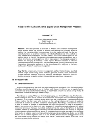
FundamentalsIntroductionAs electronic components get ever smaller andare more densely packed in enclosures andelectronic cases, systems are becomingincreasingly sensitive to external factors such asdust, oil, moisture and temperature.Heat in particular is a deadly enemy of sensitiveelectronics.DustHeatFor example, a general rule of thumb forsemi-conductors is that an increase in theoperating temperature of 10 C, in relation tothe maximum permissible operatingtemperature, will shorten its service life byone-half.In order to guarantee proper functioning of theelectronics, this heat needs to be dissipated.There are three basic forms of heat transfer:Heat conduction:Heat is transported by matter, without the matteritself being moved. The energy is passed fromparticle to particle.Heat conductionConvection:Energy flows with the matter. The transportmedium, e. g. a liquid or gas, takes up energy inthe form of heat and dissipates energy as heat.Radiation:Heat is passed from one body to another in theform of radiation energy, without a mediummaterial.The decisive factor for the type of heatdissipation to be used in enclosures is whetherthey are open (air-permeable) or closed (airtight). Whereas in open enclosures, the heat isdissipated by means of air circulation, in closedenclosures the heat can only be dissipated viathe enclosure wall.Rittal cooling units provide the ideal solution forensuring an optimum operating temperatureinside an air-tight enclosure, even at highexternal temperatures.ConvectionRadiationRittal practical tips for climate control3
FundamentalsSelection criteriaPlease bear in mind the following factors whenselecting the appropriate cooling unit for yourenclosure: What is the installation type according toVDE 0660 part 500? What ambient conditions are expected at theinstallation site? (ambient temperature andhumidity?) What is the required maximum internaltemperature of the enclosure (Ti)? What is the heat loss from electroniccomponents installed in the enclosure? Does the enclosure require a particularprotection category to EN 60 529/IEC 529? Are the cooling units exposed to any form ofambient pollution, such as dust, oil andchemicals? For bayed enclosure suites, the heat radiatedby neighbouring units may also need to betaken into account. It is important to ensure good ventilation at thesite of installation (for example, the heatdissipated by the cooling unit may cause asignificant temperature increase in smallrooms.) Particularly in the case of poor ambientconditions, such as contamination or smallrooms, it is advisable to use air/water heatexchangers. The cooling units should always be connectedvia door operated switches in order to preventexcessive condensation.Integral cooling technologyThe unity of enclosure and cooling componentsachieves particularly effective cooling. Assemblytime is eliminated. The investment costs for thecomplete unit offer exceptionally good value formoney.Roof-mounted cooling unitsRequirement-oriented routing of cooling air inthe internal circuit is possible, with up to fourcold air outlet openings and the optional use ofducts. In the external circuit, the heated air isexpelled to the rear, left and right, and optionallyupwards. This means that there are no obstaclesto bayed use and siting close to the wall.Wall-mounted cooling unitsDepending on the space and designrequirements, internal mounting, partial internalmounting and external mounting are all possible.Thanks to large distances between the air intakeand outlet openings, effective cold airthroughput of the enclosure is achieved.4Rittal practical tips for climate control
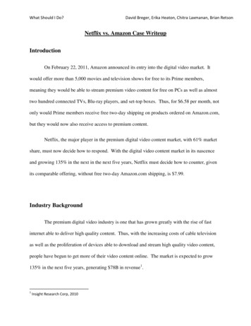
Basic calculationsGeneralHeat dissipationIn order to achieve targeted, effective cooling, itis important to ensure correct calculation of therequired climate control components andpossible thermal analysis using computerassisted flow models (CFD – ComputationalFluid Dynamics).Basic selection:TItarget TUmax.NoProt. cat. IP 54importantLouvred grille,air inlet/outlet grilleRoof vent,fan-and-filter unitYesAir/air heatexchangerTItarget or TUmaxCooling water circuitavailable atinstallation siteNoYesAir/waterheat exchangerRecoolingsystemCooling unitTI Required internal temperature of enclosure [ C]TU Ambient temperature of enclosure [ C]Calculation of effective enclosuresurface areaOf the variables required for calculationpurposes, the effective enclosure surface area Arequires an additional explanation. The thermaloutput dissipated by the enclosure not onlydepends on its actual surface area; theinstallation type of the enclosure also plays adecisive role. An enclosure which is sited in aroom unobstructed on all sides may dissipatemore heat than one sited against a wall or in aniche. For this reason, there are precisespecifications on how to calculate the effectiveenclosure surface area depending on the typeof installation site. The formulae for calculatingA are specified in DIN 57 660, part 500 andVDE 0660, part 500 (see table ).Type of enclosure installation site to VDE 0660,part 500SingleFirst or lastEnclosureenclosure,enclosure in awithin a suite, forfree-standingsuite, for wallwall mountingon all sidesmountingEnclosureSingleEnclosurewithin a suite forenclosure forwithin a suite,wall mounting,wall mounting free-standingwith covered roofFirst orareaslast enclosurein a suite, freestandingType of instal- Formula for calculating A [m2]lation site toVDE 0660/500A 1.8 x H x (W D) 1.4 x W x DA 1.4 x W x (H D) 1.8 x D x HA 1.4 x D x (H B) 1.8 x W x HA 1.4 x H x (W D) 1.4 x W x DA 1.8 x W x H 1.4 x W x D D x HA 1.4 x W x (H D) D x HA 1.4 x W x H 0.7 x W x D D x HW Enclosure width [m]H Enclosure height [m]D Enclosure depth [m]Rittal practical tips for climate control5
Basic calculationsGeneralNatural convectionIn natural convection, heat loss is dissipated tothe outside via the enclosure panels. The prerequisite for this is that the ambient temperaturemust be lower than the temperature inside theenclosure. The maximum temperature increase( T)max. which may occur inside an enclosurecompared with the ambient air is calculated asfollows:( T)max. .Qvk ANote:If the heat loss inside the enclosure is notknown, this basic formula can be used tocalculate actual heat loss, by measuring theambient temperature TU and the enclosureinternal temperature TI:.Qv A k T (watts)Basic calculations forenclosure climate control.Qv Heat loss installed in the enclosure [W].Qs Heatemitted by the enclosure surface [W].Q. s 0: Radiation (Ti Tu)Qs 0: Irradiation (Ti Tu).QK Required cooling output of an enclosurecooling unit [W].QH Required thermal output of an enclosureheater [W]qw Specific thermal output of a heat exchanger[W/K].V Required volumetric air flow of a fan-and-filterunit to maintain the maximum permissibletemperature difference between the extractedair and the emitted air [m3/h] TAk TI – TU Max. admissibletemperature difference [K] Effective, heat loss-dissipating enclosuresurface area to IEC 890 [m2] Thermal coefficient [W/m2K]for sheet steel k 5.5 W/m2KMake calculation even easier by using our projectplanning software Rittal Therm,see page 7Calculate your required cooling output.QE QV – k A TThe cooling unit may be selected using aperformance diagram.50 Hz26002400220020001800. 1600QK140012001000800600400555045403530 Ti252020 25 30 35 40 45 50 55TuT.u Ambient temperature [ C]Qk Continuous useful cooling output [W]T i Enclosure internal temperature [ C]6Rittal practical tips for climate control
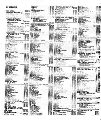
Basic calculationsEnclosure cooling unitsTherm SoftwareRittal Therm is a calculation program forclimate control of enclosures.The Therm software package (Model No.SK 3121.000) takes care of the complex processof calculating climate control requirements.A user-friendly interface guides the operator tothe most suitable, correctly dimensioned climatecontrol component.All evaluations are closely based on therequirements of IEC/TR 60 890 AMD 1/02.95 andDIN 3168 for enclosure cooling units.Rittal Therm supports 15 languages.System requirements (minimum): Windows 95/98/ME/NT/2000/XP Adobe Acrobat Reader version 4.x or aboveCalculation example for dehumidification,see page 8.Mollier h-x diagram for calculating the watercontent of air.0510 x2 1550Rittal practical tips for climate control4030%➀40One unavoidable side-effect of using coolingunits is the dehumidification of the air inside theenclosure. As it cools down, a proportion of thehumidity contained in the air condenses on theevaporator coil. This condensate must beremoved safely from the enclosure. The amountof condensation formed depends on the relativehumidity, the air temperature inside theenclosure and on the evaporator coil, and thevolume of air present in the enclosure.The Mollier h-x diagram shows the water contentof air depending on its temperature and relativehumidity.35%2035302520T30%40Condensation and dehumidificationof the enclosure air when usingcooling unitsx1 2510%45x20%50 0%6 0%7 %0% 9800%10151050–5– 10– 15– 20051015202530pd3540455055 60Pd Water vapour partial pressure [mbar]T Air temperature [ C]x Water content [g/kg dry air]➀ Relative humidity7
Basic calculationsEnclosure cooling unitsPractical tipsIn all situations where optimum operatingtemperatures are required inside an enclosure,even at high external temperatures, a Rittalenclosure cooling unit can provide the idealsolution. It is even possible to cool the interiortemperature of the enclosure to well below theambient temperature.The favourable aerodynamic arrangement of theair inlet and outlet openings in the internal andexternal circuits ensures optimum air circulationinside the enclosure. This sample calculation willshow you a quick, time-saving method forcalculating a cooling unit.W Water quantity in gV Volume of enclosure in m3ρ Density of air kg/m3 x Difference in water content in g/kg dry air(from the Mollier h-x diagram).Calculation example:An enclosure cooling unit is commissioned witha temperature setting of Ti 35 C.The relative ambient air humidity is 70%. If air at35 C is passed over the evaporator coil, thesurface temperature of the evaporator coil(evaporation temperature of the refrigerant) isapproximately 18 C.At the boundary layer adhering to the surface ofthe evaporator coil, water is deposited at thedew point. The difference x x1 – x2 indicatesthe amount of condensate incurred per kg of airwith complete dehumidification. The leaktightness of the enclosure has a decisive effecton the quantity of condensation.8The quantity of condensation is calculated usingthe following equation:W V ρ xW Water quantity in gV Volumeρ Density of the air in kg/m3 x Difference in water content in g/kgdry air (from the Mollier h-x diagram).Enclosure door closed:Only the enclosure volume is dehumidified.V W H D 0.6 m 2 m 0.5 mV 0.6 m3W V ρ x 0.6 m3 1.2 kg/m3 11 g/kgW 7.92 g 8 ml.Poorly sealed cable designs, damaged doorseals and the attachment of advertising media toenclosure surfaces lead to increased rates ofleakage in the enclosure. Hence, with a leakagerate of, say, 5 m3/h, a continuous condensatevolume of up to 80 ml/h may occur.Summary:Enclosure cooling units should only operate
Qk Continuous useful cooling output [W] T i Enclosure internal temperature [ C]. Basic calculations for enclosure climate control Qv Heat loss installed in the enclosure [W] Qs Heat emitted by the enclosure surface [W] Qs 0: Radiation (Ti Tu) Qs 0: Irradiation (Ti Tu) QK Required cooling output of an enclosure cooling unit [W]