Transcription
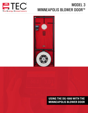
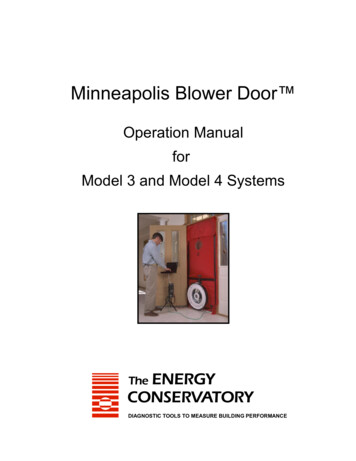
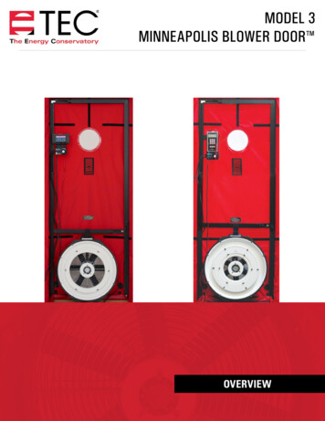
MODEL 3MINNEAPOLIS BLOWER DOOR OVERVIEW
ENERGY CONSERVATORY WARRANTYEXPRESS LIMITED WARRANTYSeller warrants that this product, under normal use and service as described in the operator’s manual, shall be free fromdefects in workmanship and material for a period of 24 months, or such shorter length of time as may be specified in theoperator’s manual, from the date of shipment to the Customer.LIMITATION OF WARRANTY AND LIABILITYThis limited warranty set forth above is subject to the following exclusions: With respect to any repair services rendered, Seller warrants that the parts repaired or replaced will be free from defectsin workmanship and material, under normal use, for a period of 90 days from the date of shipment to the Purchaser.Seller does not provide any warranty on finished goods manufactured by others. Only the original manufacturer’s warrantyapplies.Unless specifically authorized in a separate writing, Seller makes no warranty with respect to, and shall have no liability inconnection with, any goods which are incorporated into other products or equipment by the Purchaser.All products returned under warranty shall be at the Purchaser’s risk of loss. The Purchaser is responsible for all shippingcharges to return the product to The Energy Conservatory. The Energy Conservatory will be responsible for returnstandard ground shipping charges. The Customer may request and pay for the added cost of expedited return shipping.The foregoing warranty is in lieu of all other warranties and is subject to the conditions and limitations stated herein. Noother express or implied warranty IS PROVIDED, AND THE SELLER DISCLAIMS ANY IMPLIED WARRANTY OF FITNESS forparticular purpose or merchantability.The exclusive remedy of the purchaser FOR ANY BREACH OF WARRANTY shall be the return of the product to the factory ordesignated location for repair or replacement, or, at the option of The Energy Conservatory, refund of the purchase price.The Energy Conservatory’s maximum liability for any and all losses, injuries or damages (regardless of whether such claims arebased on contract, negligence, strict liability or other tort) shall be the purchase price paid for the products. In no event shallthe Seller be liable for any special, incidental or consequential damages. The Energy Conservatory shall not be responsible forinstallation, dismantling, reassembly or reinstallation costs or charges. No action, regardless of form, may be brought againstthe Seller more than one year after the cause of action has accrued.The Customer is deemed to have accepted the terms of this Limitation of Warranty and Liability, which contains the completeand exclusive limited warranty of the Seller. This Limitation of Warranty and Liability may not be amended or modified, nor mayany of its terms be waived except by a writing signed by an authorized representative of the Seller.TO ARRANGE A REPAIRPlease call The Energy Conservatory at 612-827-1117 before sending any product back for repair or to inquire about warrantycoverage. All products returned for repair should include a return shipping address, name and phone number of a contactperson concerning this repair, and the purchase date of the equipment.2
Safety Information The blower door fan should only be connected to a properly installed and tested power supply. In case of emergencies, disconnectthe power cord from the AC power mains outlet. During installation, use the nearest readily accessible power outlet and keep allobjects away from interfering with access to the outlet.Disconnect the power plug from the blower door fan receptacle before examining or making any adjustments to the fan motor,blades or electrical components.The blower door fan is a very powerful and potentially dangerous piece of equipment if not used and maintained properly.Carefully examine the fan before each use. If the fan housing, fan guards, blade, controller or cords become damaged, do notoperate the fan until repairs have been made. Repairs should only be made by The Energy Conservatory.If you notice any unusual noises or vibrations, stop and unplug the fan. If you can’t find the source of the problem, contact themanufacturer/distributor.Keep people, animals and objects away from the blower door fan when it is operating.Press the power plug firmly into the power receptacle on the blower door fan, and the AC power mains outlet. Failure to do so cancause overheating of the power cord and possible damage.Do not use ungrounded outlets or adapter plugs. Never remove or modify the grounding prong. Use only approved and inspectedelectrical wiring and connections.Do not operate the blower door fan if the motor, controller or any of the electrical connections are wet.For long-term operation, such as maintaining building pressure while air-sealing, use a flow ring whenever possible to ensureproper cooling of the blower door fan motor. This will minimize the heating of the fan and is important in warmer weather.Do not reverse the blower door fan (if the fan has a flow direction switch) while the blades are turning.The motor is thermally protected and if you experience a motor shut down, be sure to turn off the fan speed controller so that thefan does not restart unexpectedly after the motor cools down.The operator should wear hearing protection when in close proximity to the fan operating at high speed.Adjust all combustion appliances so they do not turn on during the test. If combustion appliances turn on during a depressurizationtest, it is possible for flames to be sucked out of the combustion air inlet (flame rollout). This is a fire hazard and can possibly resultin high CO levels.If there are attached spaces (e.g. townhouses) that could contain a vented combustion appliance, either adjust thoseappliances to prevent them from turning on during the test, or be sure that the attached spaces are not depressurized orpressurized when the blower door is operating.Be sure that fires in fireplaces and woodstoves are completely out before conducting a test. Take precautions to prevent ashesfrom being sucked into the building during the test. In most cases it will be necessary to either tape doors shut, clean out theashes, and/or cover the ashes with newspaper.Be sure you have returned the building to its original condition before leaving. This includes turning the thermostat and waterheater temperature controls to their original setting. Always check to see that furnace, water heater and gas fireplace pilot lightshave not been blown out during the blower door test - re-light them if necessary. Remove any temporary seals from fireplaces orother openings sealed during the test.If combustion safety problems are found, tenants and building owners should be notified immediately and steps taken to correctthe problem including notifying a professional heating contractor if basic remedial actions are not available. Remember, thepresence of elevated levels of carbon monoxide in ambient building air or in combustion products is a potentially life threateningsituation. Air sealing work should not be undertaken until existing combustion safety problems are resolved, or unless air sealingis itself being used as a remedial action.3
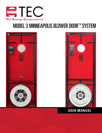
System ComponentsA standard Model 3 Minneapolis Blower Door Kit includes Blower Door Accessory Case»» Single fan nylon panel»» Fan speed controller»» 30’ clear tubing»» Gauge board with clamp»» Overview bookletAluminum frame with carrying case»» Two 96” vertical pieces»» Two 45” horizontal pieces»» One 45” crossbar with Velcro strap»» One gauge hanger barModel 3 Fan»» No flow plate»» Ring A»» Ring BOne digital pressure and flow gauge (DG-1000 or DG-700)»» DG-1000ÌÌ Carrying caseÌÌ Two Lithium Ion batteries(installed)ÌÌ Micro USB cableÌÌ Power adapter/chargerÌÌ Parts bag with fan controlcable, digital gaugeextension tube and plastichose connectorsÌÌ Screen protectorÌÌ 15’ green hoseÌÌ 10’ red hoseÌÌ Ground cable kitÌÌ Micro SD cardÌÌ Overview booklet»» DG-700ÌÌ Carrying caseÌÌ Six AA alkaline batteries(installed)ÌÌ Parts bag with fan controlcable, digital gaugeextension tube and plastichose connectorsÌÌ 15’ green hoseÌÌ 10’ red hoseÌÌ ManualBlower Door FanThe blower door fan consists of a molded fan housing with a 3/4 horsepower permanent splitcapacitor AC motor. Air flow through the fan is determined by measuring the pressure at the flowsensor which is attached to the end of the motor. When the fan is operating, air is pulled into theinlet side of the fan and exits through the exhaust side (a metal fan guard is bolted to the exhaustside of the fan). The blower door fan can accurately measure airflow over a wide range of flowrates using a series of calibrated flow rings which are attached to the inlet of the fan.4
Fan Flow RangesRingFlow Range in CFMOpen (no flow ring) 6,100 - 2,435Ring A2,800 - 915Ring B1,100 - 300Ring C (optional)330 - 85Ring D (optional)115 - 30Ring E (optional)45 - 11TEC Digital Pressure and Flow GaugesThe Minneapolis Blower Door System can come with a DG-700 or a DG-1000 Pressure and Flow Gauge. Both are differentialpressure gauges which measure the pressure difference between either of their input pressure taps and its correspondingreference pressure tap. Both gauges have two separate measurement channels which allow you to monitor the building pressureand fan pressure during a blower door test.DG-1000 Pressure and Flow GaugeFan Speed ControllerDG-700 Pressure and Flow Gauge(with optional TEC WiFi Link)Each system comes with one fan speed controller, which will work with either the DG-700or the DG-1000. Fan speed is adjusted using the adjustment knob on the face of the fanspeed controller.5
Adjustable Aluminum Door Frame and Fabric PanelOne single fan aluminum door frame and nylon panel is included with each system. The frame will come in a soft cloth frame case.Each frame consists of six separate pieces and a carrying case.One 45” crossbar with Velcro strapTwo 96” vertical frame piecesTwo 45” horizontal frame piecesCarrying case for the frameFor instructions on how to assemble the frame, please see the Blower Door Manual.One gauge hanger bar6
Model 3 Blower Door SpecificationsCOMPONENTSPECIFICATIONSModel 3 Blower Door FanMaximum Flow6,300 CFM at free air (2,973 l/s, 10,700 m3/h)5,350 CFM at 50 Pa (2,524 l/s, 9,090 m3/h)4,900 CFM at 75 Pa (2,360 l/s, 8.495 m3/h)Minimum Flow300 CFM with Ring B (141 l/s, 510 m3/h)85 CFM with Ring C (40 l/s, 144m3/h)30 CFM with Ring D (14 l/s, 51 m3/h)11 CFM with Ring E (5 l/s, 18 m3/h)Dimensions20 in. (50 cm) inlet diameter, 10.25 in (26 cm) lengthWeight33 lbs. (15 kg) with Flow Rings A & BFlow Accuracy /- 3% with DG-700 or DG-1000, Rings D & E /- 4% or 1 CFMCalibrationMeets ASTM Standard E779, E1554, CGSB-149.10-M86,Adjustable Frame and Frame MaterialEN 13829, ATTMA Technical Standard 1, NFPA 2001, RESNET and USACEPower3/4 hp motor available in 110V or 220VFrame MaterialExtruded aluminumWidth28 in. to 40 in. (71 cm to 101 cm)Height52 in. to 96 in. (132 cm to 244 cm)SealEPDM flexible gasketPanel MaterialNylon with built-in vinyl windowSpecifications subject to change without notice.Minneapolis Blower Door , TECTITE and DuctMask are trademarks of The Energy Conservatory. Duct Blaster , TrueFlow and FlowBlaster are registeredtrademarks of The Energy Conservatory. Stylized images of the Blower Door is also a Registered Trademark.7
Software InformationThe Energy Conservatory (TEC) offers a variety of Windows-based programs. These programs can be found and downloaded for freeat software.energyconservatory.com.TEC also offers driver support for the DG-500, DG-700 and DG-1000. The drivers are designed to work with Windows-basedcomputers with the following operating systems: Windows 7 Windows 8 Windows 8.1 Windows 10The drivers are available through Windows Update, and the DG-500 and DG-700 drivers can be downloaded from TEC atsoftware.energyconservatory.com.TEC also offers mobile apps for Apple and Android devices that can be found in the Apple App Store or the Google Play Store.Instructional VideosThe Energy Conservatory (TEC) offers a variety of online instructional videos, including Minneapolis Blower Door Quick Guide Minneapolis Duct Blaster Quick Guide Field Calibration Checks for Gauges Pressure and Airflow Basics Exhaust Fan Flow Meter TECLOG3 TECTITE 4.0 And many moreVisit www.YouTube.com/EnergyConservatory to see all of TEC’s instructional videos.More Blower Door GuidesAll blower door guides are available online at energyconservatory.com/blowerdoorguidesPlease refer to the guides listed below for further instructions. Minneapolis Blower Door Manual Using the DG-700 with the Minneapolis Blower Door Using the DG-1000 with the Minneapolis Blower Door Test Results and Sample Test Forms2801 21st Avenue SouthSuite 160Minneapolis, Minnesota 55407 2017 The Energy ConservatoryUpdated Aug 2017, V1Phone: (612) 827-1117Fax: (612) ory.com
A standard Model 3 Minneapolis Blower Door Kit includes Blower Door Accessory Case » Single fan nylon panel » Fan speed controller » 30' clear tubing » Gauge board with clamp » Overview booklet Aluminum frame with carrying case » Two 96" vertical pieces » Two 45" horizontal pieces » One 45" crossbar with Velcro strap