Transcription
ONBOARD VS TRADITIONALIEEE Central TennesseePARALLELINGSWITCHGEAR
Dustin SperberApplication Engineer ManagerNixon Power Services
Objective for todays meeting:To examine the latest technology in parallelingcontrols and discuss the pros and cons of each.
arallelingParallelingBest Practices
Why Parallel
Why ParallelParalleling Synchronous operation of two or more generator sets connectedtogether on a common bus in order to provide power tocommon loads.
Why Parallel?RELIABILITY:– Continue operation if one Genset fails. One large Genset failure/being serviced - entire facility is at risk.– Utilize all available sources. Many facilities have Gensets scattered from building to building withoutbeing paralleled . If the Genset for life safety/Critical loads fails, cannot utilize otherGensets on campus.REDUNDANCY:– Redundancy required for most mission critical facilities. Remove/Reduce single sources of failure. Required for Tier 2 data centers.
Why Parallel?
Why Parallel?
Why Parallel?
Why Parallel?
Why Parallel?FLEXIBILITY:– Using multiple units in parallel offers greater flexibility than a single unit(smaller units on a roof).– Can share load or run on intervals.(which prolongs engine life and reduces maintenance costs)EXPANDABILITY: Consider future needs and leave room for expansion.EASE OF MAINTENANCE AND SERVICIBILITY:– Can service/maintain one Genset while second Genset remains in standby.
Paralleling Switchgear Types Low Voltage (600V class)/Medium Voltage (5kV-15kV class)switchgear. Indoor (NEMA1) / Outdoor (NEMA 3R). Other (DO/FM Breakers, Closed Transition, DifferentialProtection).
Nine (9) Common Configurations
On-board vs Traditional Paralleling SwitchgearOn-board ParallelingATO (Assembled to order)Traditional Paralleling
Traditional SwitchgearTraditionalParalleling
MasterControl1 per systemParallelingControl1 per ionEquipment
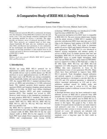
Traditional parallelingAnalog MetersMasterSoft Load/Unloadand Base LoadControlDigital PowerMonitorkW, kVAR, kVA,Frequency,Harmonics, etc. withComputer InterfaceAutomaticTransfer SwitchControlVAR/PFControlPLC ControlProtectiveRelay ModulesGeneratorSynchronizerFrequency, Phaseand VoltageMatchingPLC ulatorUtilitySynchronizerFrequency, Phaseand VoltageMatchingImport/ExportControlkW Load Sensorand kW LoadSharing ControlPLC ControlOverload/ReversePowerOver/Under ExcitationSync CheckNegative PhaseSequence CurrentNegative PhaseSequence Voltage3 Phase O/U Voltage(Typically for Generator)1 Phase O/U VoltageCircuitCircuitBreakerBreaker(Typically for Utility)Utility O/U FreqGenerator O/U Freq18
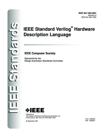
Traditional parallelingEngineered to OrderUL891 Switchboard» Up to 600V» Up to 8000 Amp BusUL1558 Switchgear» Up to 600V» Up to 10000 Amp BusUL Listed Medium Voltage» Up to 27 kV» 1200 to 4000 Amp Bus19
Traditional parallelingBENEFITS All controls for Gensets, breakers, utilities, protections in one place. When sequence of operations is more complex. Can accommodate custom configurations or solutions. More than a one utility paralleling.DRAWBACKS Maybe single source of failure due to control wiring. Larger footprint. More .20
On-BoardTraditionalParallelingParallelingOn-Board Paralleling
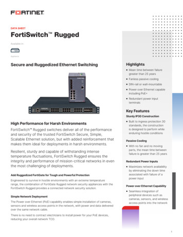
On-Board Paralleling Move the Genset paralleling fromswitchboard/switchgear to onboard the Genset Electrically operated breakers canbe mounted on the Gensets or inthe switchgear/ switchboard. Master control panel enables userto monitor system. Master alsoallows for load add/shed andGenset management22
On-Board Paralleling Components On-Board Paralleling Control–––– First on logicSynchronizerLoad / unloadProtective relaysDistribution Switchboards– Common Bus– Breakers Master Control Panel––––Generator managementLoad managementMeteringHistory23
On-Board ParallelingLet’s explore a Sequence of Operation to seehow the integrated pieces work together: When the Utility fails, the transfer switchessignal the master of the outage. The masterimmediately communicates to each on-boardgenset controller to start up. The Genset on-board Paralleling Controllerscommunicate to each other and proceed withtheir first on logic to get the first unit online asquick as possible. First on logic and Random Access parallelingcontinues as the On-board control synchronizesand parallels all available gensets to theparalleling switchboard.24
On-Board ParallelingSequence of Operation (Continued ) When the first generator set comesonline, the Priority one ATSimmediately transfers position toemergency As more generators come online,the (MCP)master control panel seesthem and Add Loads per the preprogrammed priority for each ATS. After all generators are online andthe system has stabilized, the MCPwill monitor the total capacity usingGenerator Management todetermine if the system can beoptimized. Generator management is based onKW demand of the load. The setpoints are adjustable.25
On-Board ParallelingSequence of Operation (Continued ) The MCP is constantly monitoring toensure the system is stable. In theevent of an overload, the system willLoad Shed per the pre-programmedsettings in Load Management. Upon return of Utility, the transferswitches signal the MCP which thenremoves the remote start contacts. The load is transferred back to Utilityand the generators go into cooldown, waiting vigilantly for the nextoutage. This can also all be done manuallyfrom either the MCP or Gensetmounted Controllers26
On-Board ParallelingBenefits of on-board paralleling Smaller footprint(No Genset control sections) Lower cost Smaller impact if interconnect wiring fails User interface safer. When master control is separated from switchgear. Simpler design – fewer points of failure Shorter lead time to manufactureDrawbacks of On-Board Difficult to customize Could be difficult to integrate components27
ParallelingBest PracticesParalleling Best Practices
Best Practices With onboard paralleling the EO Genset breakers can be mounted on theGenset or in the switchgear. Both examples are NEC okay. But both are not equally safe!29
Best Practices Draw-out vs fixed mounted breakers Why isolate the Gensets from Utility30
Best PracticesAvoiding single points of failure Single bus vs multiple bus. Battery failure/ best battery –Gensets batt. or paralleling station batt. Fuel supply with one pump.31
Best PracticesSIZING PARALLELD GENSETS FOR LIFE SAFETY AND CRITICAL LOADS Smallest Genset must be large enough to start all priority one(1) life safety and critical loads. To meet NFPA110 type 10 for life safety, must be able to start in 10 seconds. Make sure the smallest Genset paralleled can start all priority 1 loads.PARALLELING NATURAL GAS GENSETS: Most jurisdictions require an on site fuel source. i.e. diesel or LP. Natural gas Gensets do not react to single step loads and don’t start as fast as diesel. One option is to use diesel for priority one(1) loads.32
?Thank You!Questions?Dustin Sperberdsperber@nixonpower.comM: 615-289-8119Thank You
Paralleling Switchgear Types Low Voltage (600V class)/Medium Voltage (5kV-15kV class) switchgear. Indoor (NEMA1) / Outdoor (NEMA 3R). Other (DO/FM Breakers, Closed Transition, Differential Protection). Nine (9) Common Configurations. On-board vs Traditional Paralleling Switchgear