Transcription
Low Voltage SwitchgearCourse No: E03-039Credit: 3 PDHVelimir Lackovic, Char. Eng.Continuing Education and Development, Inc.22 Stonewall CourtWoodcliff Lake, NJ 07677P: (877) 322-5800info@cedengineering.com
LOW VOLTAGE SWITCHGEARLow-voltage switchgear is typically used name for metal-enclosed or metal-clad lowvoltage power circuit breaker switchgear rated for 600V alternating current (AC) andbelow. The metal-enclosed switchgear is completely enclosed on all sides and topwith metal sheets and has stationary primary power circuit switching or interruptingelements, or both, with buses and connections. The metal-clad low-voltageswitchgear has removable circuit breakers which are housed in individual earthedmetal compartments. There are two basic low-voltage switchgear types. They areindoor and outdoor types. Indoor switchgear consists of a front section containingcircuit breakers, meters, protection relays and controls, bus section, and cableentrance section. The outdoor section is similar to the indoor switchgear except astructure that is provided around it for weather-proofing. Bus bars can be made ofcopper or aluminum. Typically, bare bus bars are used. Nevertheless, insulation canbe specified on special orders. The normal clearance between line to line and line toground is 2 in. to minimize creepage for 600 V rated equipment. The standard highvoltage withstand is 2200 V AC for line to line and line to ground for a period of 1min. Low-voltage switchgear takes on many specific forms and functions thatcombine metering, monitoring, control, protection, and distribution. Originalequipment manufacturers (OEMs) now provide a wide variety of low-voltageswitchgear arrangements, some of them very custom, to meet the user’srequirements. It is frequent to find installations where few different kinds of circuitbreakers, automatic controls, and monitoring elements, and even automatic transferswitches, will be combined in the same line-up. This recent trend in integration hasstarted to confuse the issue as to what low-voltage switchgear really is. It needs tobe remembered that switchgear is still some principal combination of metalenclosures with multi-pole circuit breakers. There are many metal-enclosed, deadfront, assemblies offered that are switch and fuse combinations. Even though theylook like and typically are referred to as switchgear, they are really modern versionsof equipment known as switchboards. Like their forerunners, these switchboards donot address the issues with single phasing on branch feeders due to a blown fuse.Nevertheless, the incoming element may have phase loss or blown fuse detectionincluded in it. Regarding current-carrying rating, both fuses and switches have keptpace with the developments in circuit breaker technology. Low-voltage AC
switchgear arrangements are still commonly applied to low-voltage direct current(DC) distribution centers up to 250 V. In the past, manufacturers provided two-pole,draw-out circuit breakers for DC switchgear. Today, the same three-pole design, andthree-phase bus configuration, is provided for both DC and AC usages; with theextra pole either unused or installed in series with one of the others according to theparticular manufacturer’s application preferences. Direct-acting overcurrent tripelements are not typically offered for the new low voltage power circuit breakers. Thedirect-acting and electromechanical trip elements have been replaced by electronictrip elements for overcurrent protection. Nevertheless, in the insulated low voltagecircuit breakers both electronic and thermal-magnetic overcurrent trip elements areprovided. The electromechanical and direct-acting trip elements are still available inthe secondary market as replacement for the older low voltage power tchgearcontinuestobecomemorecommonplace as utilities strike agreements for cogeneration contracts. Even thoughthey are similar to unit substation type switchgear, it is vastly more advanced in theprotection and control areas. It is typical today to see low-voltage switchgear withprotective relaying that used to be found only on medium-voltage switchgear in autility’s generating station.Low-Voltage Circuit BreakersLow-voltage circuit breakers that are installed in switchgear or distribution centresare of three types:1. Molded-case circuit breakers (MCCBs)2. Insulated-case circuit breakers3. Fixed or draw-out power circuit breakers.MCCBsTypically, MCCBs can be found in a wide range of ratings and are normally used for
low-current, low-energy power circuits. The MCCBs are equipped with self-containedovercurrent trip devices. Conventional thermal-magnetic circuit breakers use athermal bimetallic part that has inverse time–current characteristics for overloadprotection and a magnetic trip part for short-circuit protection. Typical MCCBs withthermal-magnetic trip elements are dependent on the total thermal mass for theirproper tripping characteristics. This implies that the adequately sized wire and lugassemblies, which correspond to the rating of the trip element, need to be used onthe load terminals of such breakers. Numerous manufacturers are now switchingover from bimetallic parts to power sensor (electronic) type trip elements. Magnetictrip-only breakers do not have thermal element. These breakers are used only forshort-circuit protection. Molded-case circuit breakers that have only magnetic tripsare used in motor circuit protection. This configuration is desirable for smaller motorswhere their inrush current can ruin a delicate thermal element but where protectionfor winding damage is still required. The breaker provides the instantaneous (INST)protection and fault interruption, and other overload elements in the starter handlethe long-time overload protection. Non-automatic circuit breakers have no overloador short-circuit protection. Typically, they are used for manual switching andisolation.Insulated-Case Circuit BreakersInsulated-case circuit breakers are molded-case breakers. They use glass-reinforcedinsulating material for greater dielectric strength. Also, they have push-to-openbutton, rotary-operated low-torque handles with independent spring-chargedmechanism that provide quick-make, quick break protection. Different automatic tripunits are available in the insulated-case breakers. Continuous current ratings reach4,000A with interrupting capacities through 200,000A. The main differences betweeninsulated-case breakers and heavy-duty power circuit breakers are cost, size andease ofmaintenance.Insulated-case breakers arenot madewitheasytroubleshooting or repairs as the main characteristic whereas, draw-out power circuitbreakers are. To compensate for this disadvantage, many manufacturers nowprovide a variety of extra parts for insulated-case breakers that can duplicate thecharacteristics of their more expensive counterparts. Moreover, insulated-casebreakers are typically suited to light industry or commercial buildings where common
or numerous operations are not expected.Power Circuit BreakersHeavy-duty power circuit breakers use spring-operated, stored-energy elements forquick-make, quick-break manual or electric operation. Typically, these breakers havedraw-out characteristics whereby individual breakers can be put into de-energizedposition for testing and maintenance needs. The electrically operated breakers areactuated by a motor and cam system or a spring release solenoid for closing.Tripping action is actuated by one or more trip solenoids or flux-operated elements,typically one for the protective devices on the breaker itself, and another forexternally installed controls or protective elements. The continuous frame ratings forpower circuit breakers range from 400 to 4,000 A. Some manufacturers haveintroduced breakers with 5,000 and 6,000 A frames. Nevertheless, the long-termadvantages and overall reliability of these designs have yet to be proven in realoperation. Short-circuit interrupting capacities for these breakers are typically50,000–85,000 A (RMS) for frame sizes up to 4,000 A. Bigger designs haveapproached 100 kA. Power circuit breakers can be extended for usages up to 200kA interrupting when provided with assemblies or trucks made to hold Class L,current-limiting power fuses.Fused Power Circuit BreakersThe trend toward bigger unit substation transformers and bigger connected kVAloads on such substations has provided way to power circuit breakers in testedcombination with current-limiting fuses. Typically, this is done in order to increaseswitchgear short-circuit interrupting rating. This configuration can be used for allframe sizes. The fuses cause the same problems with single phasing as fuses in theswitchboards. Nevertheless, there are various characteristics that compensate forthis issue. First, most fuse assemblies are connected directly to the breakersthemselves so fuses cannot be taken out or installed unless the breaker is out ofservice. Most manufacturers solve the single-phasing issue by either an electrical ora mechanical means of blown fuse detection, which in turn makes the breaker to tripright after the fuse has cleared. On the bigger frame sizes, where the fuses must beinstalled apart from the breaker cubicle, the fuse installation is on a truck or roll-out
which is mechanically interlocked with the breaker it serves. It needs to be clear thatthe overcurrent protection for overloads is still handled by the breaker’s overcurrenttrip elements, and that the fuse is not expected to clear except for the highest shortcircuits.Overcurrent Protective saredirect-acting(electromechanical) trip (series trip) and static (electronic) trip. These overcurrentprotective elements are used in the power circuit breakers as mentioned above.Direct-Acting TripThe direct acting overcurrent trip element is commonly known as series trip,electromechanical and dashpot trip element. This element uses the force made bythe short-circuit current passing through it to trip its circuit breaker by directmechanical action. These elements are operated by (1) an electromagnetic forcemade by the short-circuit current passing through the trip element coil (the trip coil istypically connected in series with the electrical circuit or in some situations to thesecondary of current transformers) or (2) a bimetallic strip actuated by the headcreated by the fault current. Typically, the bimetallic strip is connected in series withthe circuit. Typically, a combination of thermal (bimetallic strip or equivalent) andINST magnetic trip is used on molded-case breakers to give time delay operation formoderate over-currents (overloads) and INST operation for high- magnitude of shortcircuit current. Typically, the thermal trip is nonadjustable in the field or there is someequipment that has limited range of adjustment, such as 0.8 to 1.25, whereas theinstantaneous (INST) trip is available as adjustable or nonadjustable. Theadjustable-trip range differs from low to high with several intermediate steps. Thenumber of available steps may differ for different configurations and sizes.Direct-acting trips on insulated-case and heavy-duty power circuit breakers areelectromagnetic. Three trip elements are available as: (1) long time delay (LTD), (2)short time delay (STD), and (3) INST. Combinations of these are available to provideprotection for over-currents. A trip element is installed in each phase of the electricalcircuit. The LTD, STD, and INST trip elements are available in minimum,
intermediate, and maximum time bands to allow the coordination of different tripdevices in series. All these elements have adjustable settings. The time delay bandsare accomplished by the action of the solenoid’s pull against springs, pneumatic, orhydraulic elements. Since these devices are completely mechanical, differentcharacteristics cannot be provided in a single trip element. Even though somecalibration points and some effects on the time can be changed by adjustments,totally different delay bands can be selected only by physically changing out the tripelements with others of the desired type.Direct-acting trips are still used for some installations, and are still needed on powercircuit breakers used on DC unit substations.Static- and Electronic-Trip ElementsStatic-trip elements are totally static. They have no moving parts. These elementsuse semiconductor-integrated circuits, capacitors, transformers, and other electricparts. Static-trip elements work to open the circuit breaker when the current–timerelationship surpasses a predetermined value. The energy needed to trip the breakeris obtained from the protected circuit. No external power, such as DC batteries, isneeded. The complete static-trip mechanism consists of:1. Primary circuit current transformers2. Static logic box3. Tripping actuator (a magnetically held latch element).The current transformer sensors are of toroidal type. One per phase is installed onthe circuit breaker primary studs. These transformers give a signal to the static-tripelement proportional to the primary current.The static logic box gets the signal from the primary current transformer. It checksthe signal, discovers overloads or faults, and executes the required operation in linewith predetermined settings. The tripping actuator gets the output signal from thestatic logic box and in turn causes the circuit breaker contacts to open.
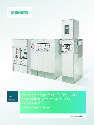
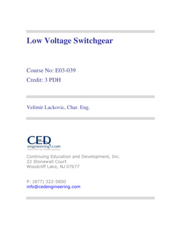
Manufacturers have put considerable effort in the development and application ofsolid-state trip elements over the past few decades. The motivation for this effort hasbeen to bring protective elements to market that provide improved characteristicsover the original direct-acting designs yet preserve the totally self-contained conceptexhibited by their forerunners. When the static trips were first introduced,manufacturers had problems to give reliable and repeatable elements that wouldprove to be lower maintenance items than the ones they replaced. These issueswere not easy to resolve. The main issue has always been related to a consistentand accurate method to both derive operational power from the signals resultingfrom current passing through the breaker, and to precisely measure the current atthe same time. The developments came one by one. For some time, manymanufacturers still had to rely on a magnetic element to provide an INST function.The configurations of that time did not allow an electronic element to build upadequate power to trip the actuator sufficiently fast to be called INST.Certain configurations have used (and may still use) two sets of current sensors, orone set of sensors with dual secondary windings, in order to derive a signal tomonitor and another to serve as the power supply. Extra sensors may be needed fora function that direct-acting trips could not provide— earth fault. Three-phase, threewire and three-phase, four-wire earth fault detection systems are provided. Thesignals from either the three or four sensors are processed to discover if all INSTcurrents add up to zero. Hence, it should be clear that if earthing conductors areused, they should not be included along with any neutral connections. When currentreturns to its source via an earth conductor, the monitored currents no longer add upto zero and the trip element operates. The connections and current sensors used fora three-phase, four-wire, plus earth conductor on a feeder breaker are presented inin Figure 1. Developments and enhancements are continuously being made on staticand electronic- trip elements. For instance, the older type static- and electronic-tripdevices measured peak and/or average currents and then scaled these currents toRMS values based on the characteristics of pure sine wave. Hence, the older staticand electronic-trip devices along with the electromechanical analog type trip devicesare susceptible to tripping issues due to harmonic currents made by nonlinear loads.The nonlinear loads are variable speed drives, switch-mode power icdevicesarecompletely
microprocessor based and are programmed to sample the current waveform atpredetermined intervals to derive the effective RMS value of the load currents.Microprocessor trip devices with RMS sensing avoid false tripping issues due toharmonic current peaks and discover the true heating current in the circuit. Also,microprocessor trip devices offer the capability for voltage, currents, kilowatts,kilowatt demands, kilowatt hours, kilovars, power factor and frequency digitalreadouts. These readouts can be local or can be transferred to a remote location viadigital communication network. Certain microprocessor protection packages offerextra protection characteristics that were originally available only by means ofinstalling extra protective relays.Ground busNeutral busPhase 1Phase 2Phase 3Tripping actuator oundlogicboxFigure 1. Functional scheme of static-trip elementAlso, the current microprocessor trip devices have lower energy demands for statictrip logic. Typically, most configurations now use less and smaller current sensorsthan would have been supplied for the breaker whose arrangement is presented inFigure 1. Not only this equipment offers all of the characteristics mentioned above
but also it can measure the true RMS current. This allows breaker to be immune tofalse tripping due to current waveforms with high distortion or harmonic content.Three current sensors are installed on the breaker and give the self-powered input tothe protection engineer. Where four-wire earth fault is specified, a fourth currentsensor is installed near the neutral bar in the cable compartment. Sensors are madeof molded epoxy for extra protection against damage and moisture. Additionalcurrent sensors with four taps are available to increase the flexibility and range of thewhole configuration. In the current designs rating plug is provided for a given sensorand breaker to make the continuous breaker rating. A flux-shift element isautomatically powered and controlled by the protection programmer and causes thebreaker to trip on signal. This low-energy positive action tripping element is placednear the trip bar on the breaker. This element automatically resets when the movingcontacts on the breaker have completely opened.Programmable microelectronic processor that forms the basis of the flexible, preciseprotection system offers:-Time–current features-Three local and remote mechanical fault sensors-Local and remote long-time pickup LED zone indicator-Selective interlocking-Integral earth-fault tripAll adjustable programmer functions are automatic and self-contained and do notneed external relaying or power supply.Monitoring and Protection PackagesA natural outgrowth of the move to static-trip elements has been to provide elementsthat can display the quantities they are monitoring. This trend has come in responseto user’s concerns regarding the convenience in monitoring loads and in
troubleshooting a given distribution network. Typically, low-voltage switchgear hasspace limitations within its breaker cubicles. Consequently mounting space for extracurrent transformers is limited. Manufacturers are starting to provide monitoringpackages that use benefits of the signals already made available by the protectionequipment. The information can be displayed on the trip element or sent to a cubicledoor mounted display. Automated data processing centres and cogeneration siteshave set up complex monitoring systems by using the benefits of thecommunications functions that are now provided. Almost every feeder at a user’s sitecan be monitored and all of its electrical performance data sent back to a centralsystem. The trend in interfacing with communications to field programming units(FPUs); remote terminal units (RTUs), programmable controllers (PLCs) used assequence controllers, data collectors and sequence control and data acquisition(SCADA) systems is expected to continue. Many of the devices used in thesesystems are mounted directly in the switchgear.FusesTwo basic families of fuses are current limiting and noncurrent limiting. The currentlimiting fuse melts and extinguishes the arc in a half-cycle or less. The noncurrentlimiting fuse may melt in less than a half-cycle when exposed to very high shortcircuit current values, but is unable to extinguish the arc in a half-cycle. Since the arcis a flexible conductor, the noncurrent-limiting-type fuse will allow the short-circuitcurrent to reach its maximum peak value. The current-limiting type of fuses areprovided with mechanisms to extinguish the arc, thereby stopping the short-circuitcurrent from reaching its maximum peak value. The fuses are used in combinationwith circuit breakers, motor starters, disconnect switches to secure protection similarto the circuit breaker overcurrent trip elements. Nevertheless, fuses have fixed time–current relationships and hence do not give the same flexibility as the overcurrentrelationships. Hence, they do not give the same flexibility as the overcurrent tripelements. Fuses cannot open and close a circuit by themselves. Fuses must becombined with some additional element, such as a disconnect switch, a circuitbreaker, or a contactor. Fuses can be divided into medium- and low-voltage fuses.
Low-Voltage FusesLow-voltage fuses are can be grouped as follows:1. Cartridge fuses that are made for the circuit protection2. Plug fuses that are made for the circuit protection3. Supplementary fuses that are made for the protection of small equipment etc.4. Special fuses that are made for the protection of electrical elements such ascapacitors, welders, and rectifiersRelevant standards to these fuses are NEMA FU-1 dated 2002, and ANSI/UL 248-1through 248-15 dated 2000. ANSI/UL 248-8 covers the class J fuses and ANSI/UL248-10 covers class L fuses. Moreover, UL has classified fuses as current limitingand noncurrent limiting, as presented in Table 1. Also, classes R, J, L, T, and CCfuses are made as branch circuit fuses appropriate for protection of distributionsystems and wiring.Table 1. Current and Noncurrent-limiting fusesNoncurrent limitingPlug fuses (C and S)Voltage rating, 125V ACCurrent rating, 0-30AInterrupting rating, not more than 10,000AClass HVoltage rating, 250 and 600 V ACCurrent rating, 0-600AInterrupting rating not more than 10,000ACurrent limitingClass JVoltage rating, 600V ACCurrent rating, 0-600AInterrupting rating, 200,000 A symClass KVoltage rating, 250-600V ACCurrent rating, 0-600AInterrupting rating 50,000-200,000 A symClass TVoltage rating, 300 and 600V ACCurrent rating, 0-600AInterrupting rating, 200,000 A symClass RK1Class LVoltage rating, 600V ACCurrent rating, 601-6000AInterrupting rating 200,000 A symClass RVoltage rating, 250 and 600V ACCurrent rating, 0-600AInterrupting rating 200,000 A symClass GVoltage rating, 300V ACCurrent rating, 0-60AInterrupting rating, 200,000 A symClass RK5
Voltage rating, 250-600V ACCurrent rating, 0-600AInterrupting rating, 200,000 A symClass CCVoltage rating, 600V ACCurrent rating, 0-30AInterrupting rating, 200,000 A symClass CA/CBVoltage rating, 300 or 600V ACCurrent rating, CA: 0-30A, CB:0-60AInterrupting rating, 200,000 A symVoltage rating, 250-600V ACCurrent rating, 0-600AInterrupting rating, 200,000 A symClass CVoltage rating, 600V ACCurrent rating, 0-1200AInterrupting rating, 200,000 A symSince fuses are single-phase interrupters, they offer good protection for single-phasecircuits. Nevertheless, for multiphase systems, single-phase interrupters can createissues such as single phasing, back feeding, and ferroresonance. Single phasingcan be damaging to motors owing to the flow of negative-sequence currents, whichcan create increased motor heating, causing motor damage or reducing its expectedlife. The degree of motor life reduction is a function of motor temperature andelapsed time between single-phase occurrence and motor de-energization.The term back feeding is used to describe the situation when fault current continuesto flow from the remaining energized phases, most probably at a decreased valueowing to the extra impedance that has been inserted in the current path. The level offault current reduction will impact the fuse time response in the remaining phases. Asfuse interrupting time grows, the degree of damage also increases. Today’sswitchgear configurations using fuses as overcurrent protective elements use antisingle phase protection characteristics. The anti-single phase characteristic in thefused switchgear open all three lines due to a single fuse blowing, therefore avertingpreviously discussed adverse effects.Disconnect SwitchesDisconnect switches are typically installed in low- and medium-voltage systems.Disconnect switches can be divided into low-voltage (600 V and below) and mediumvoltage (601 V through 15 kV) groups.Low-Voltage Disconnect SwitchesLow-voltage switches can be organised into three broad groups:
1. Isolating switches2. Safety switches3. Interrupter switchesThe isolating switch does not have interrupting or load-carrying capability. It onlyprovides isolation of the circuit or load by manual means after the power flow isstopped by the circuit protective equipment. The safety switch is a load-break switchhaving a quick-make and quick-break contact mechanism. Safety switches areinstalled in small power systems with limited short-circuit capacity. The safety switchcan be fused or unfused. The interrupter switch is of quick-make, quick-break typeand can interrupt at least 12 times its continuous current rating. They are assignedhorsepower rating. These switches can be found in continuous rating from 30 to1200 A and can part of switchboards, panel boards, and grouped motor controlcentres. The interrupter switch can be used with or without fuses depending uponthe specific installation.Certain industrial systems or commercial buildings will use switchgear orswitchboards with a high pressure or bolted pressure, three-pole switch working asincoming service main disconnects. The main characteristic of these switches is theircontinuous current ratings of up to 3000 or 4000 A. At these currents, very highcontact pressure is needed on the conducting surfaces in order to keep temperaturerises to reasonable levels. The switches themselves carry an interrupting rating thatis similar to those for three-pole interrupter switches but not as high as that for powercircuit breakers. Interrupting capacity for short circuits is almost always handled bycurrent-limiting fuses, which are an integral part of the switch. Majority ofmanufacturers offer single phase, blown fuse, and earth fault accessories so that theswitches can be installed on low-voltage service entrances. Unlike trip elementsapplied to circuit breakers, this protective equipment is not self- powered. Instead,they take operating voltage from a small control power transformer on the sourceside of the switch. Typically, the mechanical design of these switches is based on aminimum of operations. It is anticipated that the number of operations is less than forinsulated-case breakers. It is typically limited to isolation during maintenance or for
severe earth faults not successfully cleared by other methods.Selection and Application of Low-Voltage DevicesThe modern distribution systems have high short circuit current. Hence, thisdemands special consideration so that equipment may be applied within its rating.Moreover, the switchgear needs to be protected against all types of faults, from lowlevel arcing faults to bolted faults. The protection arrangement needs to be selective,meaning that the fault at a remote area in the system needs be localized withoutunnecessary tripping of either the main breaker system or any intermediatebreakers. The distribution system needs to be planned to offer continuity and servicereliability. This can be accomplished by using two or more separate distributionsystems instead of one big system. The continuous current rating of the mainprotective equipment needs to be adequate for the served load. Protectiveequipment should not be paralleled to achieve higher rating. As a general rule, thebus bars are rated on the basis of not more than 800 A/in 2 of aluminium or1000 A/in.2 of copper. The operation of protective equipment is based upon anambient temperature of 40 C, and if this equipment is to be applied at highertemperature, the manufacturer needs to be consulted. The bus short-circuit rating islimited to the interrupting rating of the lowest rated protective element, and theavailable short-circuit current should not surpass this figure.The application of circuit breakers and fuses has to be considered to determinewhich offers the most adequate protection. Attention needs to be given to anti-singlephase elements when three-pole interrupter switches with fuses are used, becausefuses are single-pole interrupter switches. An arcing fault may not be cleared by asingle-pole interruption. It can be back fed from the other live phases. Due to this,serious equipment burn downs may happen. Ferroresonance is the result ofinteraction between the reactance of a saturable magnetic equipment, such as atransformer, and system capacitance. Ferroresonance can also happen due to asingle phasing condition. This condition mainly happens in high- and medium-voltageelectrical systems and results in a very high voltage on the order of three to fivenormal system voltage which is imposed on the involved circuit, causing equipmentdamage. It is important to remember that fuses need to be used in systems where
the system voltage is compatible with the fuse voltage rating. The reason for this isthat the arc voltage created by a fuse when interrupting is few times its voltage ratingand, if misapplied, could subject the syst
Low-voltage generator paralleling switchgear continues to become more commonplace as utilities strike agreements for cogeneration contracts. Even though they are similar to unit substation type switchgear, it is vastly more advanced in the protection and control areas. It is typical today to see low-voltage switchgear with