Transcription
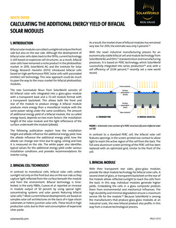
WHITE PAPERCALCULATING THE ADDITIONAL ENERGY YIELD OF BIFACIALSOLAR MODULES1. INTRODUCTIONBifacial solar modules can collect sunlight not only on the frontside but also on the rear side. Although the development ofbifacial solar cells dates back to the 1970s, current technologyis still based on expensive cell structures; as a result, bifacialsolar cells have remained a niche product in the photovoltaicmarket. In 2015, SolarWorld AG and the Institute for SolarEnergy Research Hamelin (ISFH) introduced bifacial cellsbased on high-performance PERC (solar cells with passivatedemitter) cell technology. This new approach could do muchto pave the way to the mass market for bifacial photovoltaicmodules.The new Sunmodule Bisun from SolarWorld consists of60 bifacial solar cells integrated into a glass-glass modulewith a transparent back and a 72-cell module format witha transparent backsheet. This allows both the front andrear of the module to produce energy. A bifacial moduleproduces more energy than a monofacial module with thesame power rating under the same conditions. The amountof additional energy yield of a bifacial module, the so-calledenergy boost, depends on two main factors: the installationheight of the solar module and the light reflectance of thesurface underneath the module (albedo).The following publication explain how the installationheight and albedo influence the additional energy yield, howthe albedo influence the additional energy yield, how thealbedo can change over time due to aging, soiling and howit is measured on the site. The white paper also identifiestypical values for the additional energy yield under variousinstallation conditions and provides recommendations forinverter sizing.2. BIFACIAL CELL TECHNOLOGYIn contrast to monofacial cells, bifacial solar cells collectsunlight not only on the front but also on the rear side as theycapture light reflected from the surface beneath the moduleand from the environment. Bifacial technology is timetested; in the early 1980s, Cuevas et al. reported an increasein module output of 50 percent by using special lightconcentrating systems and solar panels featuring bifacialsolar cells.[1] Most current bifacial developments are based oncomplex solar cell architectures on the basis of n-type siliconsubstrates or hetero-junction solar cells. These result in highproduction costs due to their vast consumption of expensivesilver paste.solarworld.comAs a result, the market share of bifacial modules has remainedvery low. For 2015, the estimate was only 5 percent.[2]With the novel industrial manufacturing process for aneconomically viable bifacial cell and module technology fromSolarWorld AG and ISFH,[3] standard silicon and manufacturingprocesses. It is based on PERC technology, which SolarWorldsuccessfully integrated into series production[4] and, with acell efficiency of 22.04 percent,[5] recently set a new worldrecord.Front n(rear)Rear contactsA: STANDARD PERCB: BIFACIAL SOLAR CELLFIGURE 1: Schematic cross section of a PERC structure (A) and a bifacial solarcell (B)In contrast to a standard PERC cell, the bifacial solar cellfeatures openings in the screen-printed rear contact to allowlight to reach the active region of the cell from the back. Thefull-area aluminum screen printing of the PERC cell has beenreplaced with an optimized grid, similar to the front of thecell.3. BIFACIAL MODULEWith their transparent rear sides, glass-glass modulesprovide the ideal module technology for bifacial solar cells. Asecond sheet of glass, or transparent backsheet on the rear ofthe module allows reflected sunlight to reach the cells fromthe back. In this way, individual modules generate higheryields. Embedding the cells in a glass composite protectsthem from environmental and mechanical influences. Thehigh durability and minimal degradation ensure a maximumservice life for the module.[6] Because SolarWorld is amongthe manufacturers that produce glass-glass modules at anindustrial scale, the new bifacial product also profits in thisway from a mature technological process.PAGE 1 OF 8
WHITE PAPER CALCULATING THE ADDITIONAL ENERGY YIELD OF BIFACIALSOLAR MODULESHeight of bottom edge ofmodule above groundAlbedo factor of the ground(amount of light reflected)FIGURE 2: Rear side of a bifacial module in productionIn addition to front-side power, a new relevant parameterhas been added: the bifaciality B, which describes the ratiobetween the power produced from light captured by thefront side maximum power at standard test conditions(Pmpp front): the bifaciality B, which refers to the ratio of the frontto the rear power measured under standard test conditions(STC).B Pmpp, rearFIGURE 3: Example of a system using bifacial modules4.1 ALBEDO –THE BRIGHTER THE BETTERThe albedo describes the reflectivity of a non-luminoussurface. It is determined by the ratio between the lightreflected from the surface and the incident radiation.Albedo of the surface Pmpp, frontThe first generation of bifacial SolarWorld modules hasalready achieved a bifaciality of over 65 percent. Furtherimprovements are expected as a result of ongoing solar celldevelopment.The transparent and active rear sides of bifacial photovoltaicmodules enable an additional energy yield, also known asthe “energy boost”. This is the name given to the increasein specific energy yield (kWh/kWp) of the bifacial modulecompared with the monofacial module in the same systemwith the same nominal power as the front of the bifacialmodule.4. INFLUENCES ON THE AMOUNT OF ADDITIONALENERGY YIELDThe amount of additional energy yield of a bifacial moduledepends on two main factors: the light reflectance of thesurface beneath the module[7] and the installation heightof the module. Direct or diffuse light is reflected from theground, while a portion is scattered onto the rear cell of themodule (Figure 3). When a bifacial module is installed at aheight of about 0.5 meters (distance between the bottomedge of the module and the ground)—for example, above awhite TPO roof membrane with high reflectance –up to 25percent additional yield can be generated (Table 3).Reflected lightIncident lightAlbedo is a dimensionless quantity and is usually expressedas a percentage—the higher the reflectivity of a surface, thehigher its albedo. For example, a black surface that absorbs alarge amount of light has a low albedo, while a white surfacethat reflects a large amount of light has a high albedo.Measured albedo values of common ground surfaces arelisted in Table 1. The albedo measurement for green field is23 percent. For concrete ( 10 years weathered), the value is 16percent. Adding white paint (Figure 5) boosts the albedo to 62percent. Depending on the thickness and type of paint, albedovalues of over 80 percent are possible. Additional roofingmaterials are also listed in Table 1. Surprisingly, the value forwhite gravel (Figure 4, no. 2) is only 27 percent. Due to theopen-pored structure, a large amount of reflected light is lostwithin the voids. Other flat standard construction materialslike roofing membranes or sheet metal have an albedo of 50to 60 percent. The highest albedo is measured for specialmembranes that were developed for solar applications—forexample, Renolit’s Alkobright with an albedo of 91 percent.[9]4.1.1. ALBEDO –WEAR AND TEARThe albedo of the surface under the system, one of thedecisive factors influencing the amount of the additionalenergy yield, changes in the field over time. Albedo describesthe extent to which light is reflected from a surface.PAGE 2 OF 8
WHITE PAPER CALCULATING THE ADDITIONAL ENERGY YIELD OF BIFACIALSOLAR MODULESTherefore, the albedo itself depends on the properties of thesurface under the module such as color, thickness, surfacefinish or type of vegetation. All these factors can change overtime due to environmental influences like aging, soiling orthe natural alteration of ground conditions. For example, anew white TPO roof can have an initial albedo value of 88percent, but after three years, the albedo can decrease to 75percent.[8] Although values from the literature or data sheetscan provide a good orientation, an albedo measurementshould be performed on site for a detailed calculation of theadditional energy yield.SURFACE TYPEGreen field (Grass)ConcreteWhite painted concreteALBEDO23 %16 %60-80 %White gravel27 %White roofing metal56 %Light grey roofing foilWhite roofing foil (for solar applications)62 % 80 %TABLE 1: Albedo values of certain ground surfaces measured with testsetup according to Figure 4Soiling of the surface beneath the module leads to effectssimilar to the environmental aging of the surface materialand the albedo is reduced. How strongly soiling reducesthe albedo depends greatly on the location of the installedphotovoltaic system. In many cases, rain can be sufficient towash away dirt and dust from the roof membrane. However,in cases of heavy soiling or in areas with little precipitation,additional cleaning of the roof is necessary to maintain highalbedo values. If this is required, the cost of cleaning mustbe weighed against the earnings from the additional energyyield made possible by the cleaning.The results of such a calculation depend heavily upon theindividual installation conditions of the PV system andmust therefore be individually recalculated for each system.Considerations include cleaning costs and maximumachievable additional energy yield.Table 2 shows the albedo values for roofing material underthe following conditions: un-weathered, Uncleaned, wiped,rinsed, detergent-washed and treated with algae-cleaner.[10]The uncleaned albedo values refer to a roofing membranethat was exposed to environmental influences for at least10 years. Akbari et al. demonstrated in their experimentsthat the solar reflectance of an aged and weatheredroofing membrane could be restored to at least 80 percentof the initial solar reflectance values by wiping and rinsing(simulating the annual rainfall), as long as algae did not coverthe roof membrane. Treatment of roof membranes withdetergent and algae cleaner restored the original value of theun-weathered material.[10]SAMPLENo.SOLAR REFLECTANCELocationUncleanedWipedRinsed gfield, Mass.0.540.680.700.700.820.802Springfield, Mass.0.550.730.720.760.770.823Lancaster, Ohio0.590.760.750.800.810.814Heath, Ohio0.570.720.720.780.790.805West Hampton, N.J.0.710.710.710.730.770.816West Hampton, N.J.0.690.690.710.720.770.817Plantation, Fla.0.350.430.640.650.790.828Plantation, Fla.0.320.420.590.680.800.79TABLE 2: This table shows albedo percentages as a function of location andsurface condition of white roofing membranes. [10]FIGURE 4: Ground surface albedo test: 1) white painted concrete 2) whitegravelPAGE 3 OF 8
WHITE PAPER CALCULATING THE ADDITIONAL ENERGY YIELD OF BIFACIALSOLAR MODULES4.1.2 HOW TO MEASURE ALBEDO?An albedo measurement can be performed using a solarmodule, a pyrometer or a reflectometer. For the albedomeasurement described below, a solar module was used asa measuring instrument. The test setup requires a functionalmonofacial solar module, a voltmeter (multimeter) and aframe for fixing the solar module. Although the albedo valuedoes not depend on the irradiation angle of the sunlight oron the tilt angle of the solar cell, measurement on a cloudlessday during the midday hours is recommended for the mostaccurate results.Now, the albedo of each selected testing spot is determined.The overall albedo of the surface is the arithmetic mean ofthe measured albedo values for each individual testing spot.Albedo of the surface Sum of the measured albedoNumber of measurement spotsThe measurements represent the albedo at the particular timewhen the measurement was made. Due to environmentalinfluences, these values may change over time (see section4.1.1 Albedo—Wear and Tear).4.2 INSTALLATION OF THE MODULE—THE HIGHER THE BETTERSolar panelCables of solar panelRackVoltmeterThe second main influence on the energy yield of a bifacialmodule is its installation height. Figure 6 shows simulationdata for the additional energy yield for a landscapemounted bifacial module (one module per row, 30 pitch,south orientation, 2.5 meter row pitch, 80 percent albedo)with variable installation height. The installation height ismeasured between the lower edge of the module and theground.25%Flat roof or ground20%The tester should measure the surface reflectance at at-leastthree randomly selected testing spots on the roof or groundwhere the photovoltaic system is to be installed. The spotsshould be representative of the test surface. The solar panel isthen fixed on a frame in such a way that the solar cells of themodule face the sky at a 180 angle to the hypothetically flatground. Alternatively, an actual prospective framed systemmay be used. If the bifacial module is to be assembled laterat a 10 angle, the test described here may be performed witha frame system with a 10 pitch.The frame should be at least high enough so that no shadowfrom the frame, module or person falls directly under thesolar module. Then the short circuit current of the moduleis measured twice. For this, the solar cells of the moduleare oriented once to the sky (Isc, sky) and once to the ground(Isc, ground), measuring the associated short circuit currents.Based on the measured short circuit current values, thealbedo of this testing spot can be calculated according to thefollowing formula:Isc sky 100%Albedo of the measurement spot Isc,groundEnergy boostFIGURE 5: Schematic test setup for measuring albedo with a solar module15%10%5%0%00.20.40.60.81Installation height [m]FIGURE 6: Energy boost of a bifacial photovoltaic system with landscapemounted module, south oriented, 30 pitch and a row pitch of 2.5 meters,80 percent albedoThe greater the installation height of the bifacial photovoltaicmodule—the greater the additional energy yield. However,Figure 6 shows that the saturation curve reaches itsinflection point at an installation height of about 0.5 meters.Beyond this point, the additional energy yield only increasesslightly—although the installation height continues toincrease constantly. The curve reaches its saturation point forinstallation heights above 1 meter.PAGE 4 OF 8
WHITE PAPER CALCULATING THE ADDITIONAL ENERGY YIELD OF BIFACIALSOLAR MODULES25%20%Energy boostThe recommended height of a ground-mounted system isapproximately 1 meter. On flat roofs, the installation heightis limited by increasing wind loads. The smaller the increasein uplifting loads—the higher the module is positioned onthe roof. A mounting structure with an installation heightgreater than 0.3 meters between the lowest module edgeand the roof—exhibits an optimum tradeoff among the costof the substructure and ballast weight as well as the energyyield.15%10%5%0%00.30.40.516% albedo27% albedo56% albedo23% albedo40% albedo80% albedoFIGURE 8: Additional energy yield of a bifacial photovoltaic system withlandscape-mounted module, 65 percent bifaciality, south orientation, 30 pitch and a row pitch of 2.5 meters for various albedo values (source: owncalculation)SURFACE TYPEsandwhite roofing bright whitemetal sheetroofing foilconcretegreen fieldwhite gravel16 % albedo23 % albedo27 % albedo40 % albedo56 % albedo0.01.20 %1.70 %2.00 %3.00 %4.20 %6.00 %0.12.30 %3.30 %3.90 %5.80 %8.10 %11.60 %0.23.10 %4.40 %5.20 %7.70 %10.80 %15.50 %ALBEDOINSTALLATION HEIGHT (m)Figure 7 below, shows a mounting concept for bifacial solarmodules. The depicted system has a module tilt angle of30 and a distance of about 0.3 meters between the lowermodule edge and the roof. The additional energy yield thatcan be generated in such systems is shown in Figure 5 andTable 3.0.2Installation height [m]5. AMOUNT OF ADDITIONAL ENERGY YIELDThe advantages of the Sunmodule Bisun, such as itsmechanical resilience, longer service life and additionalenergy yield, make the bifacial module the ideal solution forall commercial, industrial and agricultural applications—inparticular, in a flat-roof or ground-mounted system. For suchapplications, the module is installed so that sufficient lighthits the active module rear. When combined with a brightsurface beneath the module, e.g. whitewashed concreteor white roofing foil, even more light is reflected onto themodule. In this way, the energy yield can be further increased.0.180 % albedo0.33.60 %5.20 %6.10 %9.10 %12.80 %18.20 %0.44.00 %5.80 %6.80 %10.10 %14.10 %20.20 %0.54.30 %6.20 %7.30 %10.80 %15.10 %21.50 %TABLE 3: Additional energy yield of a bifacial module for different surfacetypes and installation heights (landscape-mounted module, 65 percentbifaciality, south oriented, 30 pitch and a row pitch of 2.5 meters) (source:own calculation)6. CALCULATION OF ADDITIONAL ENERGY YIELDThe values in Figure 5 and Table 3 are determined accordingto the following formula:FIGURE 7: Mounting system concept for bifacial modules on flat roofsPAGE 5 OF 8
WHITE PAPER CALCULATING THE ADDITIONAL ENERGY YIELD OF BIFACIALSOLAR MODULESKey to formula:a 1.037A row pitch between the modulesE 2.718B 8.691H distance between the lowest point on the moduleframe and the roof or groundc 0.125The formula applies to installations under the followingconditions:Module tilt: 10 to 30 degreesModule orientation: SouthModule mounting: landscape or portraitA calculation of the additional energy yield for theSunmodule Bisun could look like this:7.1 VOLTAGE AND THERMAL COEFFICIENTThe voltage range and thermal coefficient of bifacial modulesbased on crystalline PERC cell technology (Sunmodule Bisun)are the same as for monofacial modules based on the sametechnology (Sunmodule Plus, Sunmodule Protect). Thebifaciality does not affect the thermal properties of the celland has only a negligible effect on the voltage of the module(compare Figure 9 and Figure 10). Since the voltage andthermal coefficient of bifacial and monofacial modules areidentical, the same planning and design rules apply for bothtypes of modules in terms of inverter sizing.The input current range of the inverter may need to bechecked. The data sheet specifications for the electrical valuesunder optimized conditions can be used for this purpose.Usually, modern inverters have higher tolerances with regardto the input currents and can also process the higher currentswithout problems.7.2 NOMINAL POWERa 1.037A 2.5 meterse 2.718b 8.691H 0.3 metersc 0.125Albedo 0.8 (80 percent surface reflectance)Bifaciality 0.65 (65 percent cell bifaciality)The result of the calculation is an additional energy yield of21.5 percent. SolarWorld offers the possibility of calculatingthe additional energy yield online on its website using asmall calculation program that includes the same formula asshown above.7. INVERTER SIZING EQUIVALENT TO MONOFACIALMODULESInverter sizing is a much-discussed problem. The followingsection will provide a recommendation for inverter sizingfor photovoltaic systems that include bifacial modules.Inverter sizing generally depends on the following modulecharacteristics: Input current and voltageThermal coefficientNominal powerThe modules produce the type plate power under standardtest conditions (STC) with a solar irradiation of 1,000 W/ m²and a temperature of 25 Celsius. These favorable conditionsusually occur only during certain times of the year, e.g. onsunny days in fall or spring, when it is not too hot. In thewinter, the solar irradiation is not strong enough to raise themodule output to its nominal power. In the summer, the celltemperature is usually above 25 Celsius, so that the modulepower decreases according to the thermal coefficient.6%10 %20 %25 %Pmax285 Wp295 Wp319 Wp331 Wp39.0 VEXTRA ENERGYMaximum powerOpen circuit voltageMaximum power point voltageShort circuit currentMaximum power point voltageModule efficiencyUoc39.0 V39.0 V39.0 VUmpp31.0 V30.9 V30.6 V30.5 VIsc9.84 A10.21 A11.14 A11.60 AImppηmEXTRA ENERGYMaximum powerOpen circuit voltageMaximum power point voltageShort circuit currentMaximum power point voltageModule efficiency9.20 A9.55 A10.42 A10.85 A16.99 %17.57 %19.03 %19.72 %SW 260SW 265SW 270Pmax260 Wp265 Wp270 WpUoc38.9 V39.0 V39.2 VUmpp30.7 V30.8 V30.9 VIsc8.18 A9.31 A9.44 AImpp8.56 A8.69 A8.81 A15.51 %15.81 %16.1 %ηmFIGURE 9: Data sheet values for electrical properties of Sunmodule Bisun(top) and Sunmodule Plus (bottom) [11]PAGE 6 OF 8
WHITE PAPER CALCULATING THE ADDITIONAL ENERGY YIELD OF BIFACIALSOLAR MODULESWhen the DC power produced by the PV array exceeds themaximum input level of the inverter, the inverter adjusts thedirect current to reduce the DC power. This process is alsoreferred to as clipping.SUNMODULE BISUN 270 WP MONOTHERMAL CHARACTERISTICSNOCTTK IscTK UocTK Pmpp46 C0.040 %/K-0.30 %/K-0.41 %/KSUNMODULE PLUS 270 WP MONOTHERMAL CHARACTERISTICSNOCTTK IscTK UocTK Pmpp46 C0.040 %/K-0.30 %/K-0.41 %/KFIGURE 10:Data sheet values for thermal coefficients of the monofacialSunmodule Plus 270 Wp mono (right) and the bifacial Sunmodule Bisun270 Wp mono (left) [11]In general, clipping occurs only when the PV system isoperated under optimal conditions similar to standard testconditions. The inverter operates at a lower efficiency over 95percent of the time over the course of the year. An invertersized according to the nominal power of the front side of thebifacial module has a higher DC load (higher DC/AC ratio).It can therefore be operated at higher efficiencies for mostof the year due to the additional yield produced by the rearside of the cell. In this system, clipping might occur sooneror more often than in a photovoltaic system with the samenominal power as monofacial modules. Nevertheless, theseclipping losses are lower than overall gain that is producedwhen the inverter operates at a higher efficiency throughoutthe year (Figure 11).System powerMax. input power (DC)of inverterEnergy yield of systemwith monofacial modules:inverter operates at lowerefficiency level due tolower DC to AC ratioEnergy level of systemwith bifacial modules:inverter operates at higherefficiency level due tohigher DC to AC rationTime8. CONCLUSIONIn late 2015, SolarWorld AG introduced a new generation ofbifacial modules to the market. The Sunmodule Bisun is abifacial solar panel with a bifaciality of 65 percent and more.The additional energy yield of the Sunmodule Bisun dependson installation conditions, particularly the height of themounting frame and the light reflectance (albedo) of the roofmembrane or the ground conditions beneath the module.System planners and developers can influence both factors.General findings show that the greater the installationheight of the module, the higher the energy yield. Althoughtechnical features such as wind loads can limit the actualheight of the mounting frame, installation heights of at leastone meter are recommended for ground-mounted systemsand 0.3 meters for installations on flat roofs.The same rule applies for the albedo as for the installationheight: the higher the albedo, the higher the energy yield.The highest value the albedo can theoretically reach is 1(extremely bright or reflective surface), and the lowest valuefor albedo is 0 (perfect black surface). Un-weathered brightroof membranes reach albedo values of 80 to 90 percent.Aging and soil can reduce these values to varying extents.However, cleaning can restore the albedo of a weathered roofmembrane to 80 percent or more of the initial un-weatheredvalue.An equally important factor in the design of a photovoltaicsystem is inverter sizing. Here, it is recommended that theinverter be sized for a bifacial module in the same way it is fora monofacial module—exclusively using the power producedby the front of the bifacial module. Because the voltage rangeand thermal coefficient do not change compared with amonofacial module of the same cell type and performance,the same rules can be applied for them as for monofacialmodules.An optimal combination of reflective surface and the highestpossible system height can achieve an additional energyyield of up to 25 percent. In the field, this makes it possible tofurther reduce the cost of energy produced by photovoltaicmodules for all applications.Energy losses due to clipping at lower efficiency levels(occurs on 1–5% of days per year)Energy losses due to clipping at higher efficiency levelsAdditional energy yield generated by bifacial energy boostand inverter operating at higher efficiency level (occurs every day of the year)FIGURE 11: Idealized energy yield curves of photovoltaic systems withmonofacial modules and with bifacial modulesPAGE 7 OF 8
WHITE PAPER CALCULATING THE ADDITIONAL ENERGY YIELD OF BIFACIALSOLAR MODULESREFERENCES1. Cuevas et al., “50% more output power from an albedo collecting flatpanel using bifacial solar cells;” Solar Energy Vol. 29 No. 5 pp. 419-420, 19822. International Technology Roadmap for Photovoltaic (ITRPV.net),2014 Results, April 2015. Available at http://www.itrpv.net/Reports/Downloads/2015/ [accessed on 17 June 2015]3. Dullweber et al, “The Perc Cell: A 21%-Efficient Industrial Bifacial PercSolar Cell,” 31st European Photovoltaic Solar Energy Conference, Hamburg,Germany, 20154. T. Weber et al., “High Volume Pilot Production of High Efficiency PERC SolarCells - Analysis Based on Device Simulation,” SiliconPV, 20135. SolarWorld news release 14.01.2016 n-generation/6. SolarWorld news release, May 2015. Available at http://www.pv-tech.org/news/intersolar europe solarworld to launch glass glass bifacialmodules [accessed on 17 June 2015]7. Amy Lindsay, Matthieu Chiodetti, Patrick Dupeyrat, Didier Binesti, EricLutun, Khalid Radouane. Key Elements in the Design of Bifacial PV PowerPlants; PVSEC 20158. Cool Roof Rating Council, Rated Products Directory, data for product ID:0628-0011, available at http://coolroofs.org/products/results [accessed on 08December 2015]9. Cool Roof Rating Council, Rated Products Directory, data for product ID:1116-0001, available at http://coolroofs.org/products/results [accessed on 08December 2015]10. Hashem Akbari, Asmeret A. Berhe, Ronnen Levinson, Heat Island Group,Lawrence, Stanley Graveline, Ana H. Delgado, Ralph M. Paroli. Aging AndWeathering Of Cool Roofing Membranes, Lawrence Berkeley NationalLaboratory, 200511. SolarWorld AG, product data sheet, available at r-modules/downloads/SW9002US 160921PAGE 8 OF 8
modules enable an additional energy yield, also known as the "energy boost". This is the name given to the increase in specific energy yield (kWh/kWp) of the bifacial module compared with the monofacial module in the same system with the same nominal power as the front of the bifacial module. 4. INFLUENCES ON THE AMOUNT OF ADDITIONAL ENERGY .