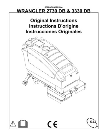
Transcription
OPERATION MANUALWRANGLER 2016 ABWRANGLER 2016 DBIMPORTANT SAFETY INSTRUCTIONSWARNING: Failure to observe these instructions can causepersonal injury to machine operator or bystanders.WARNING: Fire or explosion hazard.WARNING: Fire or explosion hazard.NEVER operate this machine in anNEVER attempt to pick up flammable orexplosive atmosphere (grain dust,combustible materials or use such materialsflammable liquids or fumes, etc.).in tank.WARNING: Orange Oil (D-limonene) is not compatible with the plastics used in NSSautomatic scrubbers and the Sidekick Chemical Metering System. Use of D-limonene mayresult in damage to the machine.WARNING: This product contains a chemical known to the state of California to causecancer and birth defects or other reproductive harm. NEVER allow this machine to be used as a toy.INTENDED USEThis machine is intended for commercial use,scrubbing floors in an indoor environment. NSSdoes not recommend using this machine for anyother purpose.FOR SAFETY: ALWAYS read and understand all instructionsbefore operating or servicing machine. ALWAYS use this machine ONLY as described inthis manual. NEVER attempt to operate this machine unlessyou have been trained in its operation. NEVER allow an untrained person to operate thismachine. NEVER attempt to operate this machine if it is notworking properly or has been damaged in anymanner. NEVER disconnect or modify any switches orsafety devices (circuit breaker). NEVER drop or insert any object into any machineopening. NEVER operate this machine with any air openingblocked. Keep all air openings free of dust, lint,hair, etc. NEVER pick up anything that is burning orsmoking, such as cigarettes, matches or hotashes. NEVER spray this machine with water or anyliquids. NEVER allow the vacuum motor or batterycharging plug to get wet or a short may occur. NEVER operate this machine when the batterycharger is plugged in. NEVER operate this machine with the bumperguard removed. Close attention is necessary when used by or nearchildren.ALWAYS wear clean tennis shoes or “non-slip”shoes. Leather soled shoes will become extremelyslippery when wet.ALWAYS keep face, fingers, hair or any other bodypart or loose clothing away from any machineopening or moving part (revolving brush, pad driver,or vacuum motor).ALWAYS turn the machine off when attaching padsor brushes.ALWAYS remove keys when this machine is leftunattended.ALWAYS be sure that the ramp is secured to thevehicle before attempting to load / unload.ALWAYS use extreme caution when operating themachine on a ramp or loading / unloading thismachine into or out of a truck / trailer. Use extremecaution if the ramp is wet, oily, or covered withcleaning chemicals.NEVER stop or turn the machine on a ramp orincline.NEVER attempt to climb a grade or operate thismachine on a ramp or incline of more than 8 degrees.NEVER park or store the machine near a dock, onramps, near a furnace, boiler, open flame, or otherhigh heat source.NEVER allow this machine to freeze.NEVER expose the machine to rain, snow, orextreme temperatures.NEVER store any items on this machine.ALWAYS store this machine indoors in a dry, coolarea.ALL REPAIR SERVICE MUST BE PERFORMED BY AN NSS AUTHORIZED DISTRIBUTOR /SERVICE STATION USING ONLY NSS ORIGINAL EQUIPMENT PARTS.ORIGINAL INSTRUCTIONSSAVE THESE INSTRUCTIONS
IMPORTANT SAFETY INSTRUCTIONSBATTERY POWERED EQUIPMENT WITH ON BOARD CHARGERSWARNING: Failure to observe these instructions can cause personalinjury to machine operator or bystanders.No smoking, openflames, or sparks whileworking with batteries.Contains acid.Avoid contactPoison. Causessevere burns. Avoidcontact.Shock or electrocutionhazard.WARNING: Batteries emit hydrogen, which can cause fire or explosion.NEVER smoke, light a match, or cause a spark during operation or charging.ALWAYS charge in a well-ventilated area away from open flame.GENERAL ALWAYS read and understand all instructionsbefore installing or charging batteries. NEVER attempt to install or charge batteriesunless you have been trained to do so. NEVER allow an untrained person to install orcharge batteries. ALWAYS remove all jewelry when working on ornear the batteries. ALWAYS turn off all switches during installationand service. ALWAYS disconnect the battery leads beforeperforming any service or repair. ALWAYS wear eye protection and protectiveclothing to avoid contact with battery acid. NEVER lay anything on top of batteries as arcingmay occur. IF CONTACT WITH BATTERY ACID OCCURS,follow these instructions: SKIN – rinse area with water. EYES – Flush with water for 15 minutes. INTERNAL – Drink water or milk. Follow withMilk of Magnesia, beaten egg or vegetable oil.Call a physician immediately.BATTERY INSTALLATION ALWAYS use two people to install, as batteriesare heavy. ALWAYS position batteries as shown on themachine installation decal to maintain machinebalance. ALWAYS connect batteries as shown on themachine installation decal to avoid shorting outthe batteries and the electrical system.BATTERY CHARGING ALWAYS read instructions on charger carefully. ALWAYS use the NSS supplied charger with propervoltage rating.For flooded lead acid batteries only (does not apply toAGM or Gel cell batteries): ALWAYS check to ensure the battery water level coversthe battery plates before charging. ALWAYS check water level after charging and adddistilled water if necessary tobring level to the bottom of the fillhole. NEVER overfill batteries as batteryand machine damage may result. ALWAYS wipe any acid from the top of batteries using asoap solution. ALWAYS study battery manufacturers’ specificprecautions such as recommended rates of charge. ALWAYS reattach caps to batteries. Do not charge withcaps loose or removed. ADD only distilled water.For all battery types: NEVER charge a frozen battery. ALWAYS plug the charger into an earthed socket outlet. NEVER touch uninsulated portion of output connector oruninsulated battery terminal. ALWAYS disconnect the AC supply before making orbreaking the connections to the battery while charging. NEVER operate charger if the AC supply cord isdamaged or if the charger has received a sharp blow,been dropped, or otherwise damaged in any way. ALWAYS keep flammable materials away from charger.ALL REPAIR SERVICE MUST BE PERFORMED BY AN NSS AUTHORIZED DISTRIBUTOR/SERVICE STATION USING ONLY NSS ORIGINAL EQUIPMENT PARTSSAVE THESE INSTRUCTIONS
IMPORTANT SAFETY INSTRUCTIONSGROUNDING OF ELECTRICAL EQUIPMENT - BATTERY CHARGERWARNING: Improper connection of the equipment–groundingconductor can result in a risk of electric shock. Check with a qualifiedelectrician or service person if you are in doubt as to whether the outletis properly grounded. Do not modify the plug provided with thecharger. If outlet is not suitable for safe use; have a properly groundedoutlet installed by a qualified electrician.Always use a properly grounded 3-wire extension cord, which hasmale and female plugs. If 25 foot extension cords are used, theelectrical carrying capacity should be no less than 14-3 ST., 50-footextension cords no less than 12-3 STGROUNDING INSTRUCTIONSThis charger shall be grounded while in use to protect the operator from electric shock. The charger isprovided with a three-conductor cord and a three-contact grounding type attachment plug. The plug must beplugged into an appropriate outlet that is properly installed and grounded in accordance with all local codesand ordinances. The green conductor in the cord is the ground wire. Never connect this wire to other thanthe grounding pin of the attachment plug.Check nameplate on the charger to be sure voltage and cycle stated is the same as the electrical outlet. Donot attempt to plug a 120-volt charger into a 240-volt outlet or a 240-volt charger into a 120-volt outlet. If thecord provided with the charger has an attachment plug as shown in Figure A. below, it is intended for use on anominal 120-volt circuit. If a properly grounded receptacle as shown in Figure A is not available, an adaptermay be installed as shown in Figure B if the outlet box that houses the receptacle is grounded. Be sure tofasten the grounding tab (the green colored rigid ear, lug or the like extending from the adapter) with a metalfaceplate screw.If the cord provided with the charger has an attachment plug as shown in Figure C, it is intended for use on anominal 240-volt circuit (single phase only). Changes to the attachment plug or use of adaptors to other plugtypes must be done in accordance with local regulations.NOTE: In Canada, the use of a temporary adaptor may not be permitted by Canadian electrical code.ALL REPAIR SERVICE MUST BE PERFORMED BY AN NSS AUTHORIZED DISTRIBUTOR/SERVICE STATION USING ONLY NSS ORIGINAL EQUIPMENT PARTS.SAVE THESE INSTRUCTIONS
NOISE AND VIBRATIONNOISESound pressure level at OperatorpositionVIBRATIONWeighted RMS acceleration value(ISO 5349)72 dB(A).575 m/s2MACHINE INSPECTION Now that the machine is unpacked remember torecycle all packing materials. Inspect the machine for damage or missingcomponents. If damage is found, contact the localfreight company to file a freight claim.MACHINE COMPONENTSSolution TankThe solution tank is the lower part of the machine bodyand has a capacity of 16 gal (60.5 L). The amount of water in the tank is measured in theplastic tube at the right rear of the tank. The solutiontank is emptied through the clear plastic tube at theright rear of the tank.Recovery TankThe recovery tank is the upper part of the machine bodyand has a capacity of 17 gal (64.3 L). A round clearview lid assembly closes off therecovery tank’s opening. The recovery tank has a foam sensitive float shut-offassembly. As the water level rises, the float ball willrise into the tube and shut of the airflow of thevacuum. NOTE: The float shut-off assembly doesnot shut off the vacuum motor.Operator Control PanelThe operator control panel is located at the upper reararea of the machine. This panel has components thatcontrol various machine functions. The toggle switch on the left controls the brush motor. The toggle switch on the right controls the vacuummotor. The red button is the master power switch; it controlsthe power to all components. Power on, is indicatedby the Battery Meter.Battery MeterThe battery meter is located on the left side of theoperator control panel and shows the state of charge ofbatteries during operation.The battery meter is equipped with a relay that willopen, turning off the machine, when the battery voltagehas dropped to its lowest permissible level. When the batteries are fully charged, all of the LED’sare illuminated. As the batteries discharge, the LED’s start to turn off,one at a time, from right to left. When the last yellow LED on the left starts blinking,there is only a few minutes of runtime left before themachine is automatically turned off. NOW is the timeto turn off the brushes and vacuum motor, and driveto the battery charging area. If the machine is operated until it is automatically shutoff, turn off the master switch, the brush switch, andthe vac switch. Then turn on the master switch, andthe machine can be driven to a charging location(wheel drive models only).Circuit Breaker The circuit breakers are located to the left of thehandle grips. The right circuit breaker is for the vacuum motor. The left circuit breaker is for the brush motor.Wheel Drive models: The center circuit breaker is for the drive motor. In the middle of the panel are two (2) rubber twistgrips. These grips rotate forward and backward tocontrol the direction and speed of the machine. Thefarther the grips are rotated, the faster the machinewill move. These twist grips have a feature thatreturns the machine to the neutral position when thehandles are released.Solution Control (Valve) Lever The solution control lever is located on the left rearside of the machine. This lever controls the solutionvalve and the amounts of liquid put on the floor whencleaning. Pull up on the handle to open the valve.Push down on the handle to close the valve. Thecontrol lever can be placed in notches to maintaindesired flow between the open and closed position.Solution Filter Assembly Attached to the solution control valve is a canisterstrainer designed to stop debris from entering thesolution solenoid valve. If the solution stops flowing to the brush, close thesolution control valve and unscrew the canister bowl(by hand), remove and clean the screen.Battery Compartment Drain HoseThis hose is tucked up under the lower right side of thecontrol panel. The spilled liquids from the batterycompartment collect in it. A pinch clamp is used to holdit closed. Inspect the hose for liquid level on a weekly basis. Dispose of liquids according to your local and federalregulations.Brush Gear MotorThis machine has a 24-volt brush motor located at thefront of the machine. The motor is attached to agearbox to turn the pad driver or brush. The right lift arm is used to raise or lower the brushmotor to and from transport, float, or heavy scrubpositions. This motor has carbon brushes that must be servicedon a regular basis. The carbon brushes have anexpected life of 2,000 operating hours. Refer to themaintenance section later in this book.Vacuum MotorThis machine has a 24-volt vacuum motor.
The vacuum motor is mounted to the underside of therecovery (top) tank. This motor has carbon brushes that must be servicedon a regular basis. The carbon brushes have anexpected life of 700 operating hours.Wheel Drive models:Drive MotorThis machine is powered forward and reverse by a 24volt drive motor. The speed is electronically controlled for smoothincrease and decrease in speed. The motor moves the drive wheels through a gearboxand transaxle system. This motor has carbon brushes that must be servicedon a regular basis. The carbon brushes have anexpected life of 2,000 operating hours.Squeegee AssemblyThe squeegee assembly is available in both straightand curved. The straight squeegee uses a dual (2)urethane blade system. The “curved” squeegee has aurethane rear blade and neoprene front blade.PREPARING THE MACHINEInstalling the Batteries: Turn off all switches and tilt the recovery tank open toexpose the battery compartment. Batteries are heavy - use two people to install. Refer to the wiring diagram inside the batterycompartment. Align batteries in the compartment asshown on the diagram. Install battery cables as shown on the wiring diagram. Tighten bolts and hex nuts with a wrench.Caution: Do not short across two terminals with awrench. Possible personal injury may occur. Loose or improper battery connections will causebattery or machine damage and possible personalinjury. Charge the batteries before use!Battery Charging To recharge the batteries plug the charger cord,located at the rear of the machine, into an electricaloutlet (100/115/230 50/60HZ VAC). When the cord is plugged into an outlet the machinewill become disabled.See Battery Charger section for more details.Preparing the Solution and Recovery tanks: Never use water over 140 F (60 C) degrees. Excessively hot water may damage components suchas the tanks. Make sure the drain plug of the recovery tank isclosed tightly and in its holding clip. Put 1 to 2 gallons of clean water into the solution tankfirst to help dilute the chemicals and prevent excesssudsing. Dilute the cleaning chemicals according tothe manufacturer’s instructions. Fill the tank by pouring the water and cleaningchemicals through the mesh filter that covers theopening at the front of the solution tank. Always use a defoamer to protect the vac motor. Consult your local distributor for complete chemicaladvice.Install a pad driver and pad: There is a wide range of pads or brushes available forthe many cleaning applications of this machine.Consult your local NSS distributor for applicationrecommendations. Turn the pad driver upside down on the floor andremove the pad holding cup. Remove the center cutout of the pad. Place the padon the face of the pad driver. The pad must be centered on the driver to preventwobbling or bouncing. Install and secure the pad holding cup to the paddriver. Turn the pad driver over so that the pad facesthe floor. Raise the brush motor into the transport position. Align the slots of the pad driver with the lugs of thedrive casting. Turn the pad driver until it stops and stays in place.Install a Brush: Raise the brush motor into the transport position. Align the slots of the brush with the lugs on the drivecasting. Turn the brush until it stops and stays in place.Install the squeegee assembly: Place the squeegee lift handle in the storage (up)position. The squeegee assembly mounts to a metal bracket atthe rear center of the machine, using two (2)mounting knobs. Loosen the mounting knobs andslide the squeegee assembly onto the mounting plate. The squeegee assembly has two (2) small wheels toprevent “rollover” while in reverse. The roller wheelsmust face the operator. Hand tighten the mountingknobs. Do not use pliers to tighten knobs, as this willdefeat the “breakaway” design. Do not add any weights or other pressure to thesqueegee mechanism. This will not improve theperformance and will shorten the life of the blades. It is recommended that, with new blades, the rearwheels be adjusted to their lowest position. Loosenthe two screws on the bracket rotate the bracketdownward as far as it will go, then tighten the screws.Perform this adjustment on both wheels/brackets. When the squeegee becomes worn, and the wipingedge no longer contacts the floor properly, further usemay be possible by adjusting the rear wheels upwardenough to restore proper engagement of the bladeswiping edge with the floor. Be sure to adjust thewheels back down fully when a new blade is installed.
Operating the MachineThe Wrangler 2016 has the brush motor offset to theright side of the machine. This offset allows you toclean the edge of a floor or an obstructed area (walls orshelving) with the right side of the machine.Normal Cleaning Sweep and dust mop the floor to remove dirt anddebris before scrubbing. Accumulations of dirt ordebris on the floor will reduce cleaning performance. You may also need to preclean some types of spillsor stains before scrubbing. Plan your work so that you make long, straight pathswith the fewest amount of turns possible, overlappingeach cleaning path about 2 in. (5 cm.) to preventstreaking and dirty areas. Move machine to area to be cleaned. Place “Wet Floor” warning signs in area. Turn on master switch. Turn on vacuum motor switch. Lower the brush motor and squeegee assembly intothe operating position on the floor. AB Models - The brush motor is turned on and offwith the brush switch on the control panel. DB Models - The brush motor will automatically turnon when moving either forward or backwards. Lift solution valve handle to start liquid flow to floor.Adjust amount of flow as needed. Close the solutionvalve completely 10 ft (3 m) before you turn at theend of your cleaning path. This will reduce theamount of liquid on the floor when you make yourturn. Reopen the solution valve when starting the nextpass. Repeat this procedure for each pass. NOTE: Solution will not flow until brush turns on. Watch the level of liquid in the recovery tank andlisten for the float shut-off to change the sound of thevac motor. When the vacuum airflow stops, you mustturn off the vacuum motor and empty the recoverytank. Take the machine to an approved disposal drain andturn off all switches. Pull the flexible rubber drain hose out from behind thebrush motor. Raise the end of the hose above thelevel of the recovery tank, loosen and remove thehose drain plug. Carefully direct the drain hose intothe drain. When the recovery tank is empty, replace and tightenthe drain plug. Place the drain hose back behind thebrush motor. Do not obstruct the lift mechanism orbrush motor.Special CleaningThis machine may be used to perform special cleaningjobs other than “normal” scrubbing.Double scrubbing This procedure provides deeper cleaning on heavilysoiled floors. One or more cleaning passes are madebefore picking up the chemicals with the squeegee.This allows dwell time. Best results are achieved byplacing the brush motor in the heavy scrub position.Caution: The floor surface becomes extremely slipperyin this operation. This machine should be operated onlyin slow to medium speed and great care should betaken when walking on this wet surface.Stripping This procedure is used to remove moderate build-upof floor finish from the floor. The most aggressivepads or brushes are used in this procedure. The stripper solution is applied to the floor with a mopand then double scrubbed as described above.Stripping solution should not be put into the solutiontank. Clean water from the solution tank is applied tothe floor to keep the chemicals and finish in a “liquid”condition. The floor surface becomes extremelyslippery in this operation. This machine should beoperated only in slow to medium speed and greatcare should be taken when walking on this wetsurface.MACHINE MAINTENANCERoutine maintenance is critical to ensure propermachine operation and cleaning performance. Performall maintenance procedures as follows.Always turn OFF all machine switches beforeperforming any maintenance.Adjusting the squeegee assembly: Turn the vacuum motor ON and open the water valveslightly. Squeegee blades should lie over slightly (like awindow squeegee) when the machine is moving. If adjustment is required adjust the blade angle byturning the wing nut on the squeegee mount.Daily MaintenanceBattery Charging The master power switch and all other switchesmust be turned OFF. You must recharge the batteries when indicated by thebattery meter, and after every use. Read the batterymeter while the machine is in use.*235 AH batteries require 8-12 hours to fully charge. Determine which Battery Charger you have - then seethe Operating Instructions for that Charger. NSS-Pro Charging: LED’s & metal housing SPE – digital display and plastic housing.Battery Electrolyte (liquid) Level (Flooded only)Inspect the electrolyte level of at least one cell in eachbattery before daily charging. The liquid must be visibleabove the internal plates. Do not charge the batteries ifthe liquid is below the plates. NEVER let the electrolyte level fall below the tops ofthe plates. This will damage the batteriesimmediately, and void the warrantee. Add only distilled water to the cell of a battery to adjustthe liquid level. Do not use well or tap water. Before
charging, add only enough water to cover the top ofthe internal plates. After charging, add only enoughwater to bring the level to the bottom of the fill tube. Do not overfill the battery liquid, this will causeelectrolyte (acid) spill. Spilled electrolyte (acid) cancause machine damage and personal injury. Cleanand dispose of spills immediately. Every cell of every battery must be checked andreplenished (if needed) once per week See the battery-warning sheet (page 2) for moredetails.Battery PackagesThe Wrangler 2016 is a 24-volt system and is availablewith two battery packages. Four (4) 6 volt, 235 Amp Hour Batteries – NSS-PCS. Two (2) 12 volt, 145 Amp Hour Batteries - SPE.Solution and Recovery Tanks The recovery tank is emptied through a large rubberhose at the front of the machine. Remove the plugand drain the liquids according to your local andfederal regulations. Every time you empty the recovery tank, werecommend that you add at least 4 to 6 ounces ofdefoamer chemical into the recovery tank beforeresuming work. Vacuum the defoamer into the emptyrecovery tank through the squeegee vac hose. At the end of the day empty all liquids from bothsolution and recovery tanks. Rinse both tanks withclean water to prevent chemical residue build-up,allow to air - dry to prevent odors. Remove any residue from screen and float ball toensure proper operation. Replace float assembly inrecovery tank. Check clear lid for airtight seal. Check the drain hose for damage. Inspect and clean the vac filter located under the topmetal plate. Every 50 hours.Pad driver or brush Remove either pad driver or brush from the machineafter use. Rinse with clean water to prevent chemical residuebuild-up. Allow to air dry on a peg or upside down on a shelf orrack. Inspect for wear or damage. Repair or replace asneeded.Squeegee Assembly Remove squeegee assembly from machine. Rinse with clean water to prevent chemical residuebuild-up. ***NOTE: prolonged exposure to some waxstripper brands may degrade the squeegee material.Rinsing after use in a wax floor stripping application ishighly recommended. Allow to air dry, it can be stored on top of the machinefor drying. Inspect the squeegee assembly, linkage, and vacuumhose, for wear, damage or obstruction. Repair orreplace as needed. Check for debris from squeegee hose at entrance torecovery tank.Weekly Maintenance (20 hours) Verify all daily maintenance has been performed. Check battery terminals and cable connections.Tighten as needed. Loose connections aredangerous and can cause personal injury andmachine damage Clean any corrosion from battery terminals andcables. Drain all liquids from battery compartment. Disposeof according to local and federal regulations. Check solution flow to pad driver and / or brush.Remove, inspect and clean solution filter assembly. Flush solution tank and hoses with a mixture of8oz/250 ml white vinegar to 1 gal/4 l water. Repair or replace any worn or damaged componentsas needed. Inspect and clean float screen and small vac filterabove float.****CAUTION****Inspect and replenish battery water in every cell inevery battery weekly. Failure to maintain properelectrolyte level in every cell of every battery will causepremature battery failure, and void the warrantee.Monthly Maintenance (100 Hours) Equalize your batteries (Flooded only). To equalizethe batteries, after they have been fully charged,unplug the charger (from the wall outlet), and plug itback in. The charger will skip thru the first fewphases of the charge cycle, and run thru the finishphase. This will balance out all the cells in thebatteries, and provide maximum battery life. THISSTEP IS ESPECIALLY IMPORTANT IF YOUPRACTICE OPPORTUNITY CHARGING. Verify all daily and weekly maintenance has beenperformed. Lube the caster and swivel bearings. Spray withSilicone Lubricant. Inspect all mechanical linkages, pivot points and balljoints for freedom of movement. Use a penetratingspray lubricant that is water resistant. Do not useWD-40 lubricant. Inspect all fasteners (bolts, screws, nuts) atmechanical linkages, pivot points and ball joints fortightness. Tighten as needed. Clean polyethylene body components to removechemical and liquid residue and maintain a “like new”appearance.Mandatory Periodic MaintenanceIt is mandatory that the following maintenance procedurebe performed at the described interval. Failure to performthis procedure may result in poor machine performance,component damage and failure. This procedure should beperformed by an NSS authorized distributor or servicecenter. Repairs not performed by an unauthorizedcompany will void the machine warranty. If you requireassistance finding an authorized service center, contactNSS Enterprises.
After every 450-500 hours of operation you must inspectvac motor carbon brushes for wear. Replace the vacuummotor carbon brushes when they are 7/16 in. (11 mm) inlength.After every 650-700 hours of operation you must inspectthe drive motor (transaxle) carbon brushes for wear.Battery ChargerThe onboard battery charger supplied with thismachine is capable of charging lead acid batteriesfrom 185 to 350ah capacity. There is no need tochange algorithms or settings based on batterymanufacturer, or battery size.The charger can also be set to charge flooded (wet)cell, AGM, or Gel batteries. LED’s on the chargerindicate which type of battery the charger is set tocharge. One setting is for Flooded and AGMbatteries, the other setting is only for GEL batteries.Depending on the battery charger model, the chargercan operate on 100/115/230 VAC 1ph 50/60 HZpower, and will automatically detect these inputvoltages. Before connecting the battery charger topower, check the label on the battery charger to verifythe proper input power.Determining Your Battery TypeCAUTION: DIFFERENT BATTERY TYPES HAVEDIFFERENT CHARGING REQUIREMENTS.FAILURE TO PROPERLY IDENTIFY YOURBATTERY TYPE, AND SET THE CHARGERACCORDINGLY WILL RESULT IN BATTERYDAMAGE, AND VOID THE WARRANTEE.Your machine may have been ordered with batteriesinstalled at the NSS factory. The standard batterytype, normally supplied by NSS, is the Flooded (wet)cell lead acid battery. Gel and AGM sealed batteriesmay also be available at customer request.Flooded (wet) batteries can be easily identified by theremovable cell caps. Removing the caps allowsinspection of the liquid electrolyte (sulfuric acid) levelin each cell.AGM (Absorbed Glass Mat) batteries are sealed,maintenance free batteries. They do not have cellReplace the drive motor (transaxle) carbon brushes whenthey are 3/8 in. (9 mm) in length.After every 650-700 hours of operation you must inspectthe brush motor carbon brushes for wear. Replace thebrush motor carbon brushes when they are 1/2 in. (13 mm)in length.caps intended for removal. Look for “AGM” printedon the tops or sides of the batteries.Gel (gelled electrolyte) batteries are also sealed,maintenance free batteries. They do not have cellcaps intended for removal. Look for “GEL” printed onthe tops or sides of the batteries.Battery Charger Indicator LED’sYour battery charger is equipped with LEDs thatindicate the following: Battery Type Setting. Either of these twoLEDs will be illuminated, anytime the chargeris plug
The toggle switch on the right controls the vacuum motor. The red button is the master power switch; it controls the power to all components. Power on, is indicated by the Battery Meter. Battery Meter The battery meter is located on the left side of the operator control panel and shows the state of charge of batteries during operation.