Transcription
Faraday Discussion 162Fabrication, Structure and Reactivityof Anchored NanoparticlesRegisternow10 – 12 April 2013, Seminaris CampusHotel, Berlin, GermanyThe last ten years have seen dramatic developments in our understanding of the surface science ofnanoparticles grown on solid surfaces. This meeting will make an excellent forum for discussion ofthe developments and points of controversy which inevitably develop within such a field.ThemesNovel chemical methods for anchorednanoparticle fabricationThe surface science of anchorednanoparticlesCO-oxidation on nanoparticles studied in-situTheoretical aspects of anchored nanoparticlestructure/reactivityScientific committeeProfessor Mike Bowker, UK (Chair)Professor Hans-Joachim Freund, GermanyProfessor Gerhard Ertl, GermanyProfessor Jens Norskov, USAProfessor Hans Niemantsverdriet,The NetherlandsProfessor Flemming Besenbacher, DenmarkInvited SpeakersProfessor Charlie Campbell (Introductory)University of Washington Seattle, USAProfessor Gabor Somorjai (Closing)University of California at Berkeley, USAProfessor Scott AndersonUniversity of Utah, USAProfessor Kiyotaka AsakuraHokkaido University, JapanProfessor Gary AttardCardiff University, UKDr Simon BeaumontUniversity of California at Berkeley, USAProfessor Richard CatlowUniversity College London, UKProfessor Matt NeurockUniversity of Virginia, USADr Niklas NiliusFHI Berlin, GermanyDr Swetlana SchauermannFHI Berlin, GermanyShowcasing work from a consortium of analysts,electrochemists and material scientists from KIST,UTS and the Gyeongsang National University.As featured in:Title: High capacity cathode materials for Li–S batteriesThis work introduces a stable sulfur cathode for high energyLi/S batteries. A sulfur–activated carbon composite is prepared byencapsulating sulfur into the activated carbon micropores by asolution-based processing technique. The elemental sulfur exists ina highly dispersed state inside the activated carbon micropores.See H. S. Ryu et al.,J. Mater. Chem. A, 2013, 1, 1573.051214www.rsc.org/FD162Registered charity number 207890www.rsc.org/MaterialsARegistered Charity Number 207890
Journal ofMaterials Chemistry APAPERDownloaded on 04 February 2013Published on 26 November 2012 on http://pubs.rsc.org doi:10.1039/C2TA00056CHigh capacity cathode materials for Li–S batteries†Cite this: J. Mater. Chem. A, 2013, 1,1573Ho Suk Ryu,a Jin Woo Park,a Jinsoo Park,a Jae-Pyeung Ahn,b Ki-Won Kim,aJou-Hyeon Ahn,*c Tae-Hyeon Nam,a Guoxiu Wangad and Hyo-Jun Ahn*aTo enhance the stability of sulfur cathode for a high energy lithium–sulfur battery, sulfur–activated carbon(S–AC) composite was prepared by encapsulating sulfur into micropores of activated carbon using asolution-based processing technique. In the analysis using the prepared specimen of S–AC composite bythe focused ion beam (FIB) technique, the elemental sulfur exists in a highly dispersed state inside themicropores of activated carbon, which has a large surface area and a narrow pore distribution. The S–AC composite was characterized through X-ray powder diffraction (XRD), transmission electronmicroscopy (TEM), Brunauer–Emmett–Teller (BET) method, selected area electron diffraction (SAED),Received 24th August 2012Accepted 8th November 2012DOI: 10.1039/c2ta00056cwww.rsc.org/MaterialsAenergy dispersive X-rayspectrometry (EDX), Fourier transformsulfur cell using the S–AC composite has a high first discharge capacity over 800 mA h g 1 S even at ahigh current density such as 2C (3200 mA g 1 S) and has good cycleability around 500 mA h g 1 Sdischarge capacity at the 50th cycle at the same current density.IntroductionThe development of high energy density rechargeable batteriesbecomes more and more important for clean and efficient energystorage and conversion technologies, such as in moderncommunication devices, electric vehicles (EVs), and electricalstorage from wind and solar power. However, batteries for largescale power applications require a much higher energy densityand low cost. In the pursuit of energy materials for lighter,cheaper and non-toxic batteries with high speci c energy,lithium–sulfur (Li–S) batteries have gained great attraction. TheLi–S battery works on the basis of redox reactions between alithium metal anode and a sulfur cathode. The combination oflithium metal with a theoretical speci c capacity of 3830 mA hg 1 as the anode and elemental sulfur (S) with a theoreticalspeci c capacity of 1675 mA h g 1 as the cathode in a battery cangenerate a high theoretical speci c energy of 2600 W h kg 1.1–3aSchool of Materials Science and Engineering, RIGET, PRC for Nano-morphicBiological Energy Conversion and Storage, Gyeongsang National University,Jinju-daero 501, Jinju, Gyeongnam 660-701, Republic of Korea. E-mail: fangy@gnu.ac.kr; ahj@gnu.ac.kr; Fax: 82-55-772-1666; Tel: 82-55-762-8657bAdvanced Analysis Center, Research Planning & Coordination Division, PRC for Nanomorphic Biological Energy Conversion and Storage, KIST, Hwarangno 14-gil 5,Seongbuk-gu, Seoul, 136-791, Republic of Korea. E-mail: jpahn@kist.re.kr; Tel: 8202-958-5536cDepartment of Chemical and Biological Engineering, Gyeongsang National University,Jinju-daero 501, Jinju, Gyeongnam 660-701, Republic of Korea. E-mail: jhahn@gnu.ac.kr; Fax: 82-55-772-1666; Tel: 82-55-772-2651dSchool of Chemistry and Forensic Science, University of Technology Sydney, CityCampus, Broadway, Sydney, NSW 2007, Australia. E-mail: Guoxiu.Wang@uts.edu.au† Electronic supplementary10.1039/c2ta00056cinfrared spectroscopy (FT-IR),thermogravimetry analysis (TGA), and field emission scanning electron microscopy (FESEM). A lithium–information(ESI)available.This journal is ª The Royal Society of Chemistry 2013SeeDOI:Recently, many results have been reported on the improvement of speci c capacity and cycling performance of the Li–Sbatteries from preparation of a sulfur–carbon composite byreduction of the sulfur particle size and the distribution of sulfurinto pores of carbon by thermal processing technology.4–16Among the many results, Li–S battery using S-mesoporouscarbon composites4,5 had high discharge capacity and goodcycle life by adsorption of reaction products in mesopores. Toprepare mesoporous carbon such as CMK, silica template SBA15 was rstly prepared with controlled morphology. A nanocasting method was used to fabricate CMK-3 from SBA-15 as ahard template which is also prepared by a complicated methodwith various processes such as mixing, pre-heating, additionand heating with high pressure. However, the reportedprocesses using mesoporous carbon involved a series ofcomplicated physical and chemical methods with the prolonged preparation time and the using of expensive materials,which is likely to offset the advantage of low-cost sulfur battery.However, activated carbon (AC) among various carbons is acommercialized and inexpensive material, originated from thecarbonization of various source materials like nutshells, peat,wood, coir, lignite, coal and petroleum pitch. AC has beenhistorically used for removal of odor, color pigments and variouscatalytic functions. It is well known that the activated carbon (AC)has micropores, various pore distribution and a high speci csurface area (SSA). Applications of activated carbon haveincreased signi cantly in the recent years with the advancementof the activation process capability and it is widely used in various elds such as adsorption of heavy metals, liquid or vapour puri cation, catalytic functions in fuel cells, anode materials, etc.17–21Recently, the AC has been applied to lithium batteries.22,23J. Mater. Chem. A, 2013, 1, 1573–1578 1573
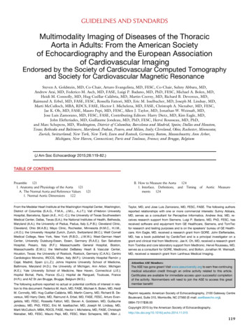
Downloaded on 04 February 2013Published on 26 November 2012 on http://pubs.rsc.org doi:10.1039/C2TA00056CJournal of Materials Chemistry APaperChen et al.22 prepared the sulfur–activated carbon composites (S–AC composites) by a mixing and heating process of twosteps: at 150 C and 300 C. They reported that the Li/S–ACcomposite battery had a high discharge capacity of 1180.8 mA hg 1 at rst discharge and a good cycle life at 720.4 mA h g 1 a er60 cycles in the low current density (100 mA g 1 S). However, theauthors did not discuss on the location, the distribution and thestate of sulfur inside activated carbon particles.In this study, we prepared an S–AC composite using an ACsuch as BP-20 through a simple solution-based processingtechnique. The S–AC composite was investigated for the location, the distribution and the state of sulfur in the S–ACcomposite by analyzing accurately through FT-IR, SAED, electron-energy loss spectroscopy (EELS), TEM, and high resolutiontransmission electron microscopy (HRTEM) combined with theFIB technique. The electrochemical properties of the S–ACcomposite were investigated with the high current density.by heating to 90 C. The AC powder was added to the solutionand dispersed by magnetic stirring for 3 h. A erward themixture was cooled to room temperature while being stirred.During cooling, the dissolved sulfur was recrystallized in theactivated carbon and formed a sulfur–carbon composite in thesolution. A er that, the composite powder was separated by acentrifuge and washed with ethanol to remove the residualDMSO several times, and then dried in a vacuum at roomtemperature to evaporate ethanol. The composite showed54.27 wt% sulfur from the result of TGA (Q50, TA instrument). Itis lower than the added sulfur powder content 76.92 wt% andalso the theoretical amount (62.15 wt%). Apparently, someamount of sulfur (22.65 wt%) did not recrystallize in thecomposite powder a er being dissolved in DMSO solvent andwas washed away by ethanol at the dissolving state.ExperimentalThe morphology of AC and the S–AC composite was observedusing a eld emission scanning electron microscope (FESEM,Hitachi S-4200) and a scanning transmission electron microscope (STEM). The pore volume, SSA and average pore diameterwere calculated using the BET method. In order to con rm thelocation, the distribution and the state of sulfur in the S–ACcomposite, it is necessary to observe sulfur in the S–ACcomposite particle.Therefore, a thin specimen for the inside of the S–ACcomposite particle was prepared by the FIB (FEI Nova 600 DualBeam FIB) technique. The S–AC composite particle was etchedexcept for a selected area using Ga liquid-metal ion sources(LMIS). A er destructive sputtering on the particle a thinspecimen piece was li ed out and mounted on a TEM and theHRTEM (FEI Titan 80-300) specimen support. All the processeswere carried out by an in situ li -out (ISLO) method. The specimen was xed by depositing platinum. The location, thedistribution and the state of sulfur in the S–AC composite wereobserved using the scanning transmission electron microscope(STEM), the TEM and EDX with S–AC composite specimen bythe FIB technique. For the state of sulfur in the S–AC composite,the FTIR data were recorded using KBr pellets on a VERTEX 80v(Bruker Optics) FT-IR spectrophotometer.Preparation of the compositeAn activated carbon (Kuraray Chemical) powder has a porevolume of 0.7932 cm3 g 1, an SSA of 1696 m2 g 1 and an averagepore diameter of 1.87 nm by result of BET analysis. Sulfur(Aldrich Co.) and AC were pre-treated at 60 C and 1000 C,respectively. A weight ratio of 10 : 3 of sulfur and AC powder wasused to prepare S–AC composites. As calculated below, the1.6419 g sulfur can fully ll the pore volume of 1 g AC. In otherwords, the maximum sulfur content is 62.15 wt% of the S–ACcomposite.Sulfur content (g) ¼ sulfur density (g cm 3) pore volume (cm3)Sulfur weight ratio in the S–AC composite (%) ¼ sulfur content/S–AC composite 100S–AC composite ¼ sulfur content carbon contentA solution-based processing technique was employed for thepreparation of S–AC composite as shown in Fig. 1. In the rststep, sulfur powder was dissolved in dimethyl sulfoxide (DMSO)Fig. 1Characterization of materialsSchematic of the solution processing for the preparation of S–AC composites.1574 J. Mater. Chem. A, 2013, 1, 1573–1578This journal is ª The Royal Society of Chemistry 2013
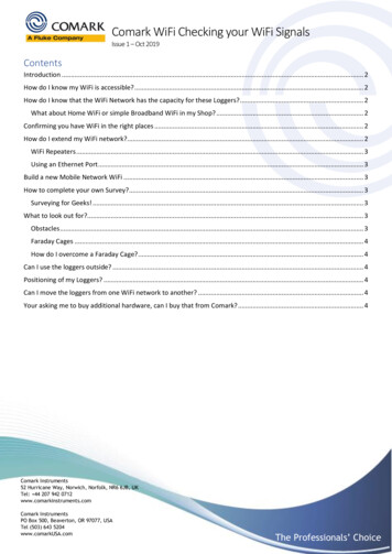
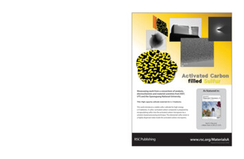
PaperJournal of Materials Chemistry ADownloaded on 04 February 2013Published on 26 November 2012 on http://pubs.rsc.org doi:10.1039/C2TA00056CElectrochemical testFor the preparation of an S–AC electrode, the S–AC composite,poly(vinylidene uoride) (PVdF, Aldrich Co.) as a binder andacetylene black (Aldrich Co.) as a conducting material werehomogeneously mixed in N-methyl-2-pyrrolidinone solventusing planetary ball milling. An S–AC electrode was composedof 60 wt% S–AC composite, 20 wt% acetylene black (AB), and 20wt% PVdF. The mixed slurry was coated on an aluminium foiland dried under vacuum at 60 C for 24 h to remove solvent andmoisture. The S–AC electrodes were punched into circular diskswith a diameter of 10 mm. A Swagelok type Li/S–AC cell wasfabricated by stacking lithium metal anode, Celgard1 2400separator lm with liquid electrolyte and S–AC cathode. Theliquid electrolyte for Li/S–AC battery was prepared by mixing1 M lithium bis(tri uoromethane sulfonyl)imide (LiN(SO2CF3)2,Aldrich Co.) in 1,2-dimethoxyethane (DME, Aldrich Co.) and 1,3dioxolane (DOXL, Aldrich). The cell assembly was performedunder an argon atmosphere in a glove box. The charge/discharge cycling tests were performed on a WonA tech WBCS3000L battery test system in galvanostatic mode with cut-offvoltages of 1.5 V and 2.8 V at room temperature. The scanningrate for the CV measurement was 0.1 mV s 1.Fig. 3 TEM and HRTEM images; AC ((a) and (b)) and S–AC composite ((c) and (d))with heat treatment (300 C for 10 min).The morphologies of AC and the S–AC composite were observedby FESEM and their surface was measured by BET. In theFESEM image of Fig. 2, both the particles show a broad sizedistribution from several tens of micron size to submicron. Inthe SEM image, the S–AC composite nearly is similar in thesurface morphology and size to AC. However, the speci csurface areas (SSA) of the S–AC composite decreased to 0.0033m2 g 1 from 1696 m2 g 1 of AC. It is proved that sulfur wassuccessfully embedded into the pores of the AC and the surfaceof the carbon was clad with sulfur.Fig. 3 shows TEM and HRTEM images of an AC particle ((a)and (b)) and an S–AC composite ((c) and (d)). Fig. 3(b) shows thetypical amorphous carbon pattern. The pores probably existbetween typical amorphous carbon patterns. In the TEM imageof the S–AC composite particle in Fig. 3(c), there is nomorphological difference from Fig. 3(a). The amorphous carbonstructure of AC was not changed a er the incorporation ofsulfur. For a clear view of the sulfur state in AC, sulfur on thesurface of the S–AC composite was removed by heating at 300 Cfor 10 min. A er heat treatment, the sulfur content of thecomposite decreased to 45.59 from 54.27 wt%. It means thatsulfur lled 73.35% of the pore volume inside AC.Fig. 4 presents a High-Angle Annular Dark-Field (HAADF)STEM image of the S–AC composite particle. In this image, thedifferent contrast is related to the different thickness of theparticle. A bright region (O1) and a dark region (O2) are referredto thick and thin areas, respectively. From the sulfur contentwith carbon thickness, the sulfur penetration depth into poresof the AC was measured by EDX. In the thick and the thin part,the ratio of sulfur and carbon was almost similar. From thisanalysis, it was proved that the homogeneity of sulfur in the S–AC composite is achieved even on the inside of the particle.Therefore, sulfur should penetrate along arbitrarily misalignedchannels of nanopores.From the results of BET and STEM, sulfur in the S–ACcomposite was in ltrated deep within the open pores on thesurface of the AC particle. However, the in ltration depth,contents and state of sulfur in the overall S–AC composite werestill unknown. To our knowledge, mesoporous carbon powderFig. 2Fig. 4Results and discussionSEM image and surface area of AC and S–AC composite.This journal is ª The Royal Society of Chemistry 2013STEM and EDX of S–AC composite.J. Mater. Chem. A, 2013, 1, 1573–1578 1575
Downloaded on 04 February 2013Published on 26 November 2012 on http://pubs.rsc.org doi:10.1039/C2TA00056CJournal of Materials Chemistry Awith average 3 nm pore diameter provides direct evidence for theexistence of sulfur in the structure by TEM observation. Nazaret al.5 reported lling the carbon channels with sulfur wascorroborated by the TEM image and EDX mapping of sulfur andcarbon clearly demonstrated that sulfur was homogeneouslydistributed in the framework of the mesoporous carbon, with nosigni cant fraction on the external surface. J. Wang et al.4reported that sulfur also exists inside the mesoporous carbon inthe amorphous state by SAED analysis of sulfur–mesoporouscarbon powder, but the sample was thick for observation of theinside of mesoporous carbon powder with several tens of nanometers. Herein, a study on ltration depth of sulfur, its content,distribution and state at the inner S–AC composite particle wascarried out using EDX, SAED, HRTEM and electron energy lossspectroscopy (EELS) with a TEM specimen of the S–AC compositeparticle by the FIB technique. Fig. 5 shows a scheme of thespecimen by FIB and a TEM image of the specimen which has athickness of a few nanometers. A composite particle was chopped like slices by high energy Ga liquid-metal ion sources. Tothe best of our knowledge, this is the rst time to investigate thestate and the content of sulfur in AC by the FIB technique.In the HRTEM image of the S–AC specimen in Fig. 6(a), thepattern of S–AC is similar to the amorphous structure of the AC.The selected area electron diffraction (SAED) pattern in Fig. 6(b)shows no characteristic rings but a blurred amorphous phase.The microstructure of the AC is maintained in spite of theexistence of sulfur inside the AC structure. In the SAED result ofFig. 6(b), the AC structure was unchanged throughout thesynthetic procedure as an amorphous state and sulfur also exitsinside the AC structure in the amorphous state. Our result is inaccordance with DSC and XRD results a er heat treatment ofthe S–AC composite for 10 min at 300 C. Except for the ACpeaks, no other peaks are found in DSC and XRD results (ESIFig. X2 and X3†). It is con rmed that the remaining sulfurinside the AC has an amorphous structure from the results ofHRTEM, SAED, DSC and XRD.Fig. 7 presents a STEM image and its EDX result in differentparts of the S–AC composite specimen. The sulfur content isslightly altered between 20 and 30 wt% in the four parts. It isindicated that sulfur is dispersed in the AC from outside toinside. The sulfur content is lower than in the TGA resultbecause of the loss of sulfur by Ga liquid-metal ion sources ofFIB.Fig. 5PaperFig. 6HRTEM image and SAED pattern of S–AC composite specimen by FIB.Fig. 8 shows FTIR spectra of sulfur powder, the AC powderand the S–AC composite. Sulfur shows vibrations at 1636, 2857,2919 and 3433 cm 1 and the AC powder has vibrations below700 cm 1. It is found that the spectra of the S–AC compositesample had similar vibrations with sulfur, indicating nochemical reaction happened between sulfur and the AC underthis synthesis method. From this result, sulfur on the inside ofthe AC has S–S bonding but does not have the S–C bond. Thisresult is proved by the EELS result (ESI, Fig. X5†) of the S–ACcomposite specimen. However, the peaks of sulfur are notobserved in the XRD and DSC results of the S–AC composite. Itis probably because the size of the covalent sulfur atom is closeto 1 Å and the S–S bonding length is 1.887 Å in S–S(S2); eventhough the status of sulfur is crystalline as S–S(S2) inside of theAC, the con ned sulfur is close to amorphous.Fig. 7 STEM image and EDX in various parts of S–AC composite specimen by FIBwith heat treatment (300 C for 10 min).Schematic of composite specimen by FIB and TEM image of the specimen.1576 J. Mater. Chem. A, 2013, 1, 1573–1578This journal is ª The Royal Society of Chemistry 2013
Downloaded on 04 February 2013Published on 26 November 2012 on http://pubs.rsc.org doi:10.1039/C2TA00056CPaperJournal of Materials Chemistry AFig. 8 FTIR spectra of the powders: (a) S, (b) AC and (c) S–AC composite withheat treatment (300 C for 10 min).Fig. 9 shows electrochemical properties of Li battery usingthe S–AC composite as the cathode active material. Fig. 9(a)shows the cyclic voltammetry (CV) curves of the S–AC compositeelectrode in the voltage window of 1.5–2.8 V. As the AC is electrochemically inert in this voltage range, the redox peaks canonly be ascribed to the redox reactions associated with sulfurand lithium ions. In the rst cycle, the CV curve has twocathodic peaks at 2.35 V and 2.08 V, which can be assigned tothe reduction processes of sulfur. The rst cathodic peak ataround 2.35 V corresponds to the reduction of elemental sulfurto polysul de. As the reduction proceeds, lithium polysul desare reduced to lithium sul des, which should be responsible forthe second cathodic peak at 2.08 V. The anodic peak of 2.27 Vand 2.42 V represents a reversible process from lithium sul desto elemental sulfur. The reactions of discharge are in accordance with the typical sulfur of chemical formulae as follows.1,24xLi S8 e / Li2Sx (2.4–2.1 V)(1)Li2Sx Li e / Li2S2 or Li2S (2.1–1.5 V)(2)From the second cycle, the intensities of the two reductionpeaks at 2.35 V and 2.08 V decrease and the reduction peaksshi slightly to a lower potential (2.32 V and 2.05 V). From theoxidation peaks of the second cycle, the peaks shi to a higherpotential slightly. However, the intensity of 2.42 V decreases,while the intensity of 2.30 V increases in the oxidation peak ofthe second cycle. A er the second cycle, the peak potential andintensity are kept unchanged in the 3rd cycle.Fig. 9(b) shows the rst charge–discharge curves of the S–ACcomposite electrodes at different current densities. Twodischarge plateaus can be easily distinguished in the voltageranges of 2.4–2.1 V and 2.1–1.5 V, respectively. These twodischarge plateaus match very well with the two cathodic peaks inthe CV curves as shown in Fig. 9(a). The S–AC composite deliversthe highest speci c discharge capacity of 1364.3, 1137.8 and801.3 mA h g 1 at 400 mA g 1 (j 0.25C), 1600 mA g 1 (j 1C) and3200 mA g 1 (j 2C) in the rst cycle, respectively.This journal is ª The Royal Society of Chemistry 2013Fig. 9 Electrochemical properties of Li battery using S–AC composite cathode;(a) CV (the scanning rate is 0.1 mV s 1) and (b) charge–discharge curves and (c)cycle life with current density.Fig. 9(c) shows the cycling performance of the S–ACcomposite electrodes at different C-rates to be 0.25C, 1C and 2C,respectively. The S–AC composite cathodes deliver the highestspeci c discharge capacity in the rst cycle and then decline fora few cycles due to easier dissolution of sulfur on the carbonsurface into electrolyte. A er the 50th cycle, the dischargecapacity of 835, 714 and 493 mA h g 1 remained at 0.25C, 1Cand 2C, respectively. It means that sulfur in the inner part of ACJ. Mater. Chem. A, 2013, 1, 1573–1578 1577
Downloaded on 04 February 2013Published on 26 November 2012 on http://pubs.rsc.org doi:10.1039/C2TA00056CJournal of Materials Chemistry Awas well retained and is difficult to be dissolved into theelectrolyte.He et al.25 reported that the sulfur composite electrodesexpanded when discharging and shrank when charging. Thethickness change of the electrode was measured to be about22%. For improving the cycle life, it is necessary to keep sulfurin carbon pores and control its content in the S–AC composite.Because the volume of the active materials was increased by theformation of lithium sul de during discharging by reactionwith lithium as in eqn (1), the loss of the active materials canoccur. By the calculation of the mass of sulfur accommodated inthe pore space from the pore volume of the AC, the suitablesulfur content in this S–AC composite is 40.78 wt%.Consequently, the high utilization of active materials and along cycle life can be obtained through the minimum loss ofactive material and the homogeneous distribution of sulfur intoAC pores by solution-based processing in this study.ConclusionsAn activated carbon with a high speci c surface area of 1696 m2g 1 is used to prepare an S–AC composite as a cathode activematerial for Li–S batteries by a novel solution-based processingtechnique. Applying the FIB technique, the state and thecontent of sulfur inside carbon micropores are rstly investigated. It is found that sulfur exists as S–S bonding and isuniformly distributed in the pores of the AC particle fromoutside to inside. Li–S batteries with the S–AC compositecathode show good electrochemical properties and highdischarge capacities over 800 mA h g 1 at 2C and about 500 mAh g 1 a er 50 cycles are obtained.AcknowledgementsThis research was supported by ‘Pioneer Research Center forNano-morphic Biological Energy Conversion and Storage’ and‘WCU Center for Next Generation Battery’ through the KoreaScience and Engineering Foundation (KOSEF) funded by theMinistry of Education, Science and Technology.Notes and references1 R. D. Rauh, K. M. Abraham, G. F. Pearson, J. K. Surprenantand S. B. Brummer, J. Electrochem. Soc., 1979, 126, 523.2 J. Shim, K. A. Striebel and E. J. Cairns, J. Electrochem. Soc.,2002, 149, A1321.1578 J. Mater. Chem. A, 2013, 1, 1573–1578Paper3 D. Peramunage and S. Licht, Science, 1993, 261, 1029.4 J. Wang, S. Y. Chew, Z. W. Zhao, S. Ashraf, D. Wexler, J. Chen,S. H. Ng, S. L. Chou and H. K. Liu, Carbon, 2008, 46, 229.5 X. Ji, K. T. Lee and L. F. Nazar, Nat. Mater., 2009, 8, 500.6 B. Zhang, C. Lai, Z. Zhou and X. P. Gao, Electrochim. Acta,2009, 54, 3708.7 L. Yuan, H. Yuan, X. Qiu, L. Chen and W. Zhu, J. PowerSources, 2009, 189, 1141.8 J.-J. Chen, X. Jia, Q.-J. She, C. Wang, Q. Zhang, M.-S. Zhengand Q.-F. Dong, Electrochim. Acta, 2010, 55, 8062.9 J.-Z. Wang, L. Lu, M. Choucair, J. A. Stride, X. Xu andH.-K. Liu, J. Power Sources, 2011, 196, 7030.10 N. Jayaprakash, J. Shen, S. S. Moganty, A. Corona andL. A. Archer, Angew. Chem., Int. Ed., 2011, 50, 5904.11 G. He, X. Ji and L. Nazar, Energy Environ. Sci., 2011, 4,2878.12 X. Liang, Z. Wen, Y. Liu, H. Zhang, L. Huang and J. Jin, J.Power Sources, 2011, 196, 3655.13 B. Zhang, X. Qin, G. R. Li and X. P. Gao, Energy Environ. Sci.,2010, 3, 1531.14 S. Li, M. Xie, J. B. Liu, H. Wang and H. Yan, Electrochem.Solid-State Lett., 2011, 14(7), A105.15 X. Li, Y. Cao, W. Qi, L. V. Saraf, J. Xiao, Z. Nie, J. Mietek,J.-G. Zhang, B. Schwenzer and J. Liu, J. Mater. Chem., 2012,21, 16603.16 M. Nagao, A. Hayashi and M. Tatsumisago, J. Mater. Chem.,2012, 22, 10015.17 L. Le Leuch, A. Subrenat and P. Le. Cloirec, Langmuir, 2003,19, 10869.18 L. Truong and N. Abatzoglou, Biomass Bioenergy, 2005, 29,142.19 M. Endo, T. Maeda, T. Takeda, Y. J. Kim, K. Koshiba, H. Haraand M. S. Dresselhausb, J. Electrochem. Soc., 2001, 148(8),A910.20 D. Qu and H. Shi, J. Power Sources, 1998, 74, 99.21 Y.-G. Wang and Y.-Y. Xia, J. Electrochem. Soc., 2006, 153(2),A450.22 F. Wu, S. X. Wu, R. J. Chen, S. Chen and G. Q. Wang, Chin.Chem. Lett., 2009, 20, 1255.23 W. Yong-Gang and X. Yong-Yao, J. Electrochem. Soc., 2006,153(2), A450.24 H.-S. Ryu, H.-J. Ahn, K.-W. Kim, J.-H. Ahn and J.-Y. Lee, J.Power Sources, 2006, 153, 360.25 X. He, J. Ren, L. Wang, W. Pu, C. Jiang and C. Wan, J. PowerSources, 2009, 190, 154.This journal is ª The Royal Society of Chemistry 2013
UTS and the Gyeongsang National University. Title: High capacity cathode materials for Li-S batteries This work introduces a stable sulfur cathode for high energy Li/S batteries. A sulfur-activated carbon composite is prepared by encapsulating sulfur into the activated carbon micropores by a solution-based processing technique.