Transcription
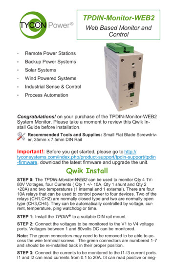
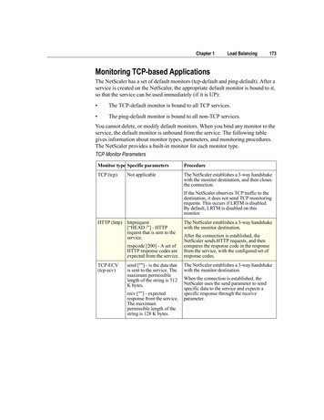
TPDIN-Monitor-WEB2Web Based Monitor andControl Remote Power Stations Backup Power Systems Solar Systems Wind Powered Systems Industrial Sense & Control Process AutomationCongratulations! on your purchase of the TPDIN-Monitor-WEB2System Monitor. Please take a moment to review this Qwik Install Guide before installation.Recommended Tools and Supplies: Small Flat Blade Screwdriver, 35mm x 7.5mm DIN RailImportant!: Before you get started, please go to tyconsys-tems.com/support/firmware, download the latest firmware foryour particular model and upgrade the unit.Security: Please be sure to set a username and password onthe Network page to secure the user interface. Also set your ownTelnet username/password and enable Telnet so that you canreboot the unit remotely in case of a browser access issue.Qwik InstallSTEP 0: The TPDIN-Monitor-WEB2 can be used to monitor Qty 4 1V80V Voltages, four Currents ( Qty 1 /- 10A, Qty 1 shunt and Qty 2 20A) and two temperatures (1 internal and 1 external). There are four10A relays that can be used to control power to four devices. Two of therelays (CH1,CH2) are normally closed type and two are normally opentype (CH3,CH4). They can be automatically controlled by voltage, current, temperature, ping watchdog or time.STEP 1: Install the TPDIN to a suitable DIN rail mount.STEP 2: Connect the voltages to be monitored to the V1 to V4 voltageports. Voltages between 1 and 80volts DC can be monitored.
Note: The green connectors may need to be removed to be able to access the wire terminal screws. The green connectors are numbered 17 and should be re-installed back in their proper position.STEP 3: Connect the currents to be monitored to the I1-I3 currentports. I1 and I2 can read currents from 0.1 to 20A. I3 can read positiveor negative currents to /-10A. I3 can be used to measure current flowing into and out of a battery to see if the battery is charging or discharging. I4 is designed to be used with a current shunt to be able to readhigher currents. It is also capable of reading /- current.STEP 4: Connect any power to devices you want to be under relay control to the CHI—CH4 10A relays. The CH1 and CH2 relays are normallyclosed relays and the CH3 and CH4 are normally open relays. Whenthe relay is in it’s default position it draws zero power. When it isswitched to the opposite position, it draws up to 0.5W. When the Open/Closed indicator in the user interface is Green, the relay is not usingany power. When it is Red, the relay is using up to 0.5W.STEP 5: Connect the External Temperature sensor to the includedgreen wire terminal connector. There is no polarity. Plug the wire terminal connector to the “Temp.” connector location. Locate the externaltemperature sensor where you want to measure external temperatures.You can extend the wire lengths if desired by soldering additional wiresto the existing wires. You can measure temperatures from –40C to 125CSTEP 6: The TPDIN-Monitor-WEB2 can be powered with 10-57VDCthru the wire terminal connector #7 or via 802.3af/at PoE or Passive24V to 48V PoE thru the RJ45 PoE/DATA port. If powered by both wireterminal and PoE port, the port with highest voltage has priority.Important!: Tycon recommends using shielded CAT5/6 cable toconnect to the RJ45 port on the TPDIN2. This will ensure propergrounding of the port.STEP 7: Download the Java based Discovery Tool from tyconsystems.com/support/firmware. Your computer must have java installed touse the discovery tool (java.com).The TPDIN-Monitor-WEB2 ships with IP addressing by DHCP enabled.The discovery tool will find the IP address of the device so you can access the web control panel. If not connected to a DHCP server the default IP address is 192.168.1.6STEP 8: Open the Web control panel of the unit by using the discoverytool or typing the units known IP address into a browser. The unit willserve up the Monitor web page. The monitor page is where all the voltage, current, temperature and relay status can be seen. Relays canalso be controlled manually from this page. There is a cycle button bythe relays if you want to automatically cycle a relay from open to closedand back. The Cycle Delay is specified on the SYSTEM page.2
You can modify any labels directly on the monitor page. Click “SaveLabels” to save your customizations.STEP 9: Open the System Page. Here you can set a static IP Address.You can also set access security by entering a user name and password (10 characters max). You can also set a unique Host Name toidentify the Monitor. Sensor offsets can be entered to fine tune thereadings to match another piece of measuring equipment or to compensate for line loss.STEP 10: Open the Relays Page. This is where you can set the relaycontrols. Relays can be controlled by Time, Temp, Voltage, Current,Ping or Periodic. The controls can be setup as compound controls somore than 1 control can be setup for a single relay. The control abovehas priority.STEP 11: Open the Alerts Page. This is where you can setup theSMTP server and various alerts. Multiple alert triggers can be set. SSLis supported.Other PagesNetwork: On this page you setup the network parameters and pass-words. Set DHCP or static addressing. If using static IP, be sure to seta valid gateway and DNS or else the email alerts won’t work. Set ausername and password to secure the web interface. Set your ownusername and password for Telnet and enable Telnet. Telnet will allowyou to reboot the unit in case there is some problem accessing the unitthrough a web browser.SNMP: You setup the SNMP access on this page. The unit supportsSNMP walking and extracting data via SNMP programs such as Cacti.The relays can also be controlled via SNMP. The unit does not supportSNMP traps.Upgrade: Go to this page to update the firmware. Download the latestfirmware from Tyconsystems.com/support/firmware. Select the downloaded file and click on “Upgrade and Reboot”. Note: Do not navigateaway from this page during upgrade or the upgrade will be aborted.Log: You will find a sequential log file of system events here. You canset the log interval on the System page. The log memory status can beseen on the Monitor Page. When the memory reaches 100% the newdata will bump the old data. The log holds 4048 records.Graph: You can graph single or multiple parameters. Click on “ShowAll” to see all the data. To print the graph do a screen capture and saveas a graphic file.3
TECH CORNERAdditional Information you may find useful1.FUSE: The TPDIN-Monitor-WEB2 has an external mini blade 2Afuse. If the TPDIN-Monitor-WEB2 doesn’t power up, check the fuse.2.LIMITS: Don’t exceed 80V on the voltage inputs or 20A on the current inputs or 10A on the relays or the unit could be damaged. Thiskind of damage isn’t covered under warranty.3.MOISTURE: The TPDIN-Monitor-WEB2 is designed to be usedindoors or outdoors in a weatherproof enclosure. Avoid getting theTPDIN-Monitor-WEB2 wet. This kind of damage isn’t covered under warranty.4.TELNET: The unit can be accessed via TELNET to see the present readings and also control the relays. You can toggle relaysusing the number keys on the computer #1-4. You can also rebootthe unit by typing “r”. Default TELNET user name admin andpassword tycon5.BATTERY STATUS: If measuring voltage of battery systems typical state of charge readings are as follows. These readings arewithout any load on the battery. For max battery life don’t dischargeunder 50%:State Of ChargeSealed or FloodedLead AcidGEL BatteryAGM Battery100%12.7 Volts12.9 Volts12.8 Volts75%12.4 Volts12.7 Volts12.6 Volts50%12.2 Volts12.4 Volts12.3 Volts25%12.0 Volts12.0 Volts12.0 Volts10%11.8 Volts11.8 Volts11.8 Volts6.Operating Power: The TPDIN-Monitor-WEB2 has extremely lowoperating power, typically less than 1.5W. CH1,CH2 relays are normally closed type and CH3,CH4 are normally open type so in typical operation they don’t use any power until they are energized. Ifthe relays are turned on, the power usage will increase by 0.5W perrelay.7. WIRE TYPE: When using the monitor in high current applications( 10A), it’s important to use a stranded wire with many fine strands.This type of wire will provide a low resistance electrical connectionto the green connectors. If using coarse strand wire such as THHN,there will be higher resistance in the connection which will generateexcessive heat at high currents, possibly causing damage to the4
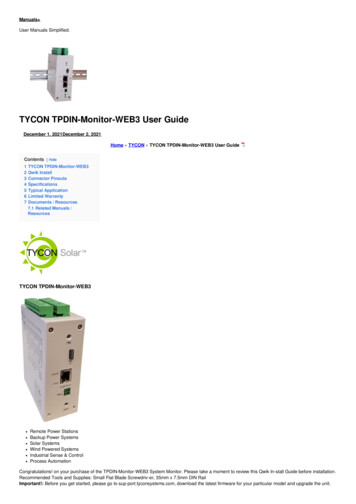
Connector PinoutsSpecificationsVoltage Measurement (DC)Voltage Meas AccuracyCurrent Measurement (DC)Current Meas AccuracyCommon Mode Volt RangeTemperature MeasurementTemp Measurement TypeTemp Measurement AccuracyRelaysRelay ControlPower e SizeMountingOperating TemperatureHumidity (RH)Dimensions (LxWxH)WeightWarrantyV1, V2, V3, V4 1-80VDC /- 0.1VI1, I2 0.1A to 20A, I3 /-10AI4 Supports Ext Current Shunts – Input Range /25mV /- 0.1A-20V to 80VT1,T2 -40C to 125CT2 Embedded, T1 External Sensor (included) /- 1 degCCH1, CH2 (NC) ; CH3, CH4 (NO) 10A 30VDC, 125-250VACCH1, CH2, CH3, CH4 Manual or Automatic basedon Volts, Amps, Temperature, Ping or Time10-57VDC Wire Terminal or802.3af/at Class 0 PoE or 24V Passive PoE1.5W All Relays Off, 3.5W All Relays OnVia Web Browser and SNMP and TelnetFIFO, Max 4048 data sets, Prog log intervalRemovable Wire Terminal12AWG MaxDIN Rail-40C to 75C (-40F to 167F)0% - 90%125 x 102 x 46mm (4.9” x 4” x 1.8”)410g (14.5 oz)3 Years5
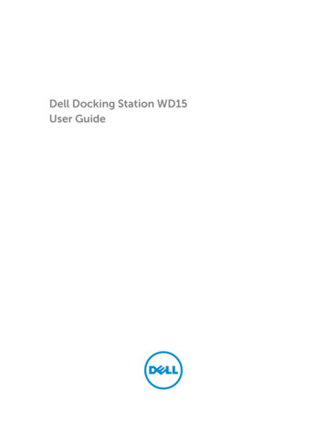
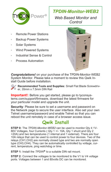
Typical Application6
connectors. NEC Wire Class C and D are acceptable.8. Reset to Factory Defaults: Power up unit. Wait at least 20 seconds. Press reset button and hold for 10 seconds to reset to factorydefaults. If reset button is held for longer than 30 seconds, the unitwill roll back to the last stable factory firmware. Only use this if theunit has an unrecoverable error.9. Shunt Resistor: The unit is capable of reading a shunt voltage upto /-25mV into I4 input. Just enter the shunt resistor ohms on thesystem page and the correct current will be displayed on the monitorpage.10. Branding: You can brand the TPDIN-Monitor-WEB2 with your ownlogo, colors and suppress the Tycon footer. Just access the custom.htm page by entering IP Address /custom.htm in a browser.You can change the parameters on this page and save. If you havemultiple units to update with your brand, get the branding correct onone unit then go to the brand.htm page. Copy and paste the code toa txt file. Open the next unit brand.htm page and upload the new textfile to the unit. All custom parameters will be uploaded from the single file.Limited Warranty The TPDIN products are supplied with a limited 36 month warrantywhich covers material and workmanship defects. This warranty doesnot cover the following: Parts requiring replacement due to improper installation, misuse,poor site conditions, faulty power, etc. Lightning or weather damage. Physical damage to the external & internal parts. Products that have been altered, or defaced. Products that have been subjected to voltages or currents greaterthan the published ratings. Water damage for units that were not mounted according to usermanual. Usage other than in accordance with instructions and the normalintended use.Notes7
8000046 Rev 5 TPDIN-Monitor-WEB2 Qwik Install Guide8
The TPDIN-Monitor-WEB2 ships with IP addressing by DHCP enabled. The discovery tool will find the IP address of the device so you can ac-cess the web control panel. If not connected to a DHCP server the de-fault IP address is 192.168.1.6 STEP 8: Open the Web control panel of the unit by using the discovery