Transcription
Stirling Engine for Solar Thermal Electric GenerationMike Miao HeElectrical Engineering and Computer SciencesUniversity of California at BerkeleyTechnical Report No. /TechRpts/2018/EECS-2018-15.htmlMay 1, 2018
Copyright 2018, by the author(s).All rights reserved.Permission to make digital or hard copies of all or part of this work forpersonal or classroom use is granted without fee provided that copies arenot made or distributed for profit or commercial advantage and that copiesbear this notice and the full citation on the first page. To copy otherwise, torepublish, to post on servers or to redistribute to lists, requires prior specificpermission.AcknowledgementI would like to thank Professor Seth Sanders for his mentorship and helpingme to be a better engineer, for his perpetual good humor and kindness, andfor always being available for his students.I would also like to thank Artin Der Minassians for his guidance and help.Thanks to Aron, Matt, Roger, Sarah, and Shai on the Cleantech-to-Marketteam for their research on the market viability of the technology. Thanks toAlan, Shong, Kelvin, Alex, and Samir and others for their help.
Stirling Engine for Solar Thermal Electric GenerationbyMike Miao HeA dissertation submitted in partial satisfaction of therequirements for the degree ofDoctor of PhilosophyinEngineering – Electrical Engineering and Computer Sciencesand the Designated EmphasisinEnergy Science and Technologyin theGraduate Divisionof theUniversity of California, BerkeleyCommittee in charge:Professor Seth Sanders, ChairProfessor Randy KatzProfessor Dan KammenSummer 2016
Stirling Engine for Solar Thermal Electric GenerationCopyright 2016byMike Miao He
1AbstractStirling Engine for Solar Thermal Electric GenerationbyMike Miao HeDoctor of Philosophy in Engineering – Electrical Engineering and Computer SciencesUniversity of California, BerkeleyProfessor Seth Sanders, ChairAddressing the challenge of climate change requires the large-scale development of significant renewable energy generation, but also requires these intermittent energy sources tobe balanced by energy storage or demand management to maintain a reliable electric grid.In addition, a centralized generation paradigm fails to capture and utilize thermal energyfor combined heat and power, abandoning a large portion of the available value from theprimary energy source. A solar thermal electric system utilizing Stirling engines for energyconversion solves both of these shortcomings and has the potential to be a key technology forrenewable energy generation. The ability to store thermal energy cheaply and easily allowsthe reliable generation of output power even during absences of solar input, and operatingas distributed generation allows the output thermal stream to be captured for local heating applications. Such a system also can achieve relatively high conversion efficiencies, isfabricated using common and benign materials, and can utilize alternate sources of primaryenergy in an extended absence of solar input.This dissertation discusses the design, fabrication, and testing of a Stirling engine as thekey component in a solar thermal electric system. In particular, the design addresses thelow temperature differential that is attainable with distributed solar with low concentrationratios and is designed for low cost to be competitive in the energy space. The dissertationcovers design, fabrication, and testing of a 2.5 kW Stirling Engine with a predicted thermalto-mechanical efficiency of 20%, representing 60% of Carnot efficiency, operating between180 C and 30 C. The design process and choices of the core components of the engine arediscussed in detail, including heat exchangers, regenerator, pistons, and motor/alternator,and the process for modeling, simulation, and optimization in designing the engine. Finally,the dissertation covers the assembly and experimental testing that validates the design interms of heat exchanger performance, losses, kinematics, and cycle work.
iTo my wife, Michelle, for loving me and supporting me throughout my graduate career.
iiContentsContentsiiList of FiguresiiiList of Tablesiv1 Introduction1.1 System Description . . . . . . . . . . . . . . . . . . . . . . . . . . . . . . . .1.2 Stirling Engine Background . . . . . . . . . . . . . . . . . . . . . . . . . . .1122 Motivation2.1 Broader Context . . . . . . . . . . . . . . . . . . . . . . . . . . . . . . . . .2.2 Applications . . . . . . . . . . . . . . . . . . . . . . . . . . . . . . . . . . . .55113 Design and Optimization3.1 Design Overview . . . . . . . . . . . .3.2 Analytical Design and Optimization . .3.3 Heat Exchangers . . . . . . . . . . . .3.4 Regenerator . . . . . . . . . . . . . . .3.5 Displacer Piston . . . . . . . . . . . . .3.6 Power Piston . . . . . . . . . . . . . .3.7 Adiabatic Simulation and Optimization3.8 Drive Train . . . . . . . . . . . . . . .3.9 Losses and Inefficiencies . . . . . . . .3.10 Pressurization . . . . . . . . . . . . . .3.11 Prototype Design . . . . . . . . . . . .2121222332343639464856594 Electrical Conversion and Motor Control4.1 Alternator Design . . . . . . . . . . . . . . . . . . . . . . . . . . . . . . . . .4.2 Drive Controls . . . . . . . . . . . . . . . . . . . . . . . . . . . . . . . . . . .6161695 Experimental Results5.1 Assembly and Verification . . . . . . . . . . . . . . . . . . . . . . . . . . . .8080.
iii5.25.35.45.5Heat Exchanger Test . . . . . .Alternator Performance . . . . .Loss Experiments . . . . . . . .Forward and Reverse Operation.818585886 Conclusion6.1 Future Work . . . . . . . . . . . . . . . . . . . . . . . . . . . . . . . . . . . .6.2 Final Words . . . . . . . . . . . . . . . . . . . . . . . . . . . . . . . . . . . .949494Bibliography96List of Figures1.11.2System Diagram . . . . . . . . . . . . . . . . . . . . . . . . . . . . . . . . . . .Ideal Stirling Cycle P-V Diagram . . . . . . . . . . . . . . . . . . . . . . . . . .2.12.22.32.4PV Installed Price . . . . . . . . . . . . . . . .PV Cumulative and Annual Installed Capacity .Diesel Cogeneration Payback . . . . . . . . . .Diesel Cogeneration Market Segments . . . . . 3.143.153.16Top and bottom CAD view of heat exchanger body. . . .Heat Exchanger Complete View . . . . . . . . . . . . . .Working Fluid Channel Flow Simulation . . . . . . . . .Heat Exchanger External-Fluid Channel . . . . . . . . .Heat Exchanger External-Fluid Channel Structural FEADisplacer isometric and section view . . . . . . . . . . .Displacer deflection . . . . . . . . . . . . . . . . . . . . .Power piston isometric and section view. . . . . . . . . .P-V Diagram from Adiabatic Simulation . . . . . . . . .Optimization sweep over piston strokes . . . . . . . . . .Optimization sweep over regenerator stack length . . . .Working Fluid Stroke Length Sweep . . . . . . . . . . .Crankshaft Unconnected . . . . . . . . . . . . . . . . . .Crankshaft Assembled . . . . . . . . . . . . . . . . . . .Displacer linear bearing housing . . . . . . . . . . . . . .Assembled Engine with Wall . . . . . . . . . . . . . . . .24252830313436374042434546474857.23
iv3.17 Pressure Vessel Drawing and Image . . . . . . . . . . . . . . . . . . . . . . . . .3.18 Stirling Cycle Energy Flow Diagram . . . . . . . . . . . . . . . . . . . . . . . .3.19 Engine Photographs . . . . . . . . . . . . . . . . . . . . . . . . . . . . . . . . .5859604.14.24.34.44.54.64.74.84.94.10Magnet rotor disc . . . . . . . . . . . . . .Assembled winding structure . . . . . . .Full rotor and stator assembly . . . . . . .Flux density versus rotor angle and fourierAspect Ratio Optimization . . . . . . . . .Normalized Aspect Ratio Optimization . .Custom Norm Level-Set . . . . . . . . . .Speed Control . . . . . . . . . . . . . . . .Control Block Diagram . . . . . . . . . . .Control Schematic . . . . . . . . . . . . .5.15.25.35.45.55.65.7Engine Assembly Pictures . . . . . . . . . . . . . . . .Electric Heater . . . . . . . . . . . . . . . . . . . . . .Comparison of BackEmf from design and measurementSpinning Losses Experiment Descriptions . . . . . . . .Waveforms from Engine Test . . . . . . . . . . . . . .PV Diagrams in Heat Pump mode . . . . . . . . . . .PV Diagrams in Engine mode . . . . . . . . . . . . . . . . . . . . . . . . . . . . . . . .components. . . . . . . . . . . . . . . . . . . . . . . . . . . . . . . . . . . . . . . . . . . . . . . . . . . . . . . . . . . . . . . . . .62636465676875767779.82838687909192List of Tables2.12.22.32.4Engine Capitol Costs . . . . . . . . . . . . .Installed Price for Stirling vs PV . . . . . .Full-Value Installed Price for Stirling vs PVDiesel Generator Specifications . . . . . . .141416173.13.23.33.43.53.6Mesh longest path thermal resistances.Heat exchanger thermal resistances. . .Heat exchanger temperature drops. . .Important regenerator properties. . . .Displacer properties . . . . . . . . . .Power Piston properties . . . . . . . .262930333639.
v3.73.83.93.103.113.12Stirling engine losses .Bearing Components .Peak Piston Forces . .Conduction path lossesStirling engine losses .Temperature drops . .4548485054605.15.25.35.45.55.65.75.8Heat exchanger conduction test temperature dropsHeat exchanger temperature drops. . . . . . . . . .Heat Pump Equilibrium Thermal Test . . . . . . .Heat Pump Equilibrium Thermal Test . . . . . . .Spinning Losses Measurements and Predictions . .Heat Pump Work . . . . . . . . . . . . . . . . . . .Heat Pump and Engine Work Values . . . . . . . .Combined Heat Pump and Engine Analysis . . . .8384858587939393
viAcknowledgmentsI would like to thank Professor Seth Sanders for his mentorship and helping me to be abetter engineer, for his perpetual good humor and kindness, and for always being availablefor his students.I would also like to thank Artin Der Minassians for his guidance and help. Thanks toAron, Matt, Roger, Sarah, and Shai on the Cleantech-to-Market team for their research onthe market viability of the technology. Thanks to Alan, Shong, Kelvin, Alex, and Samir andothers for their help.
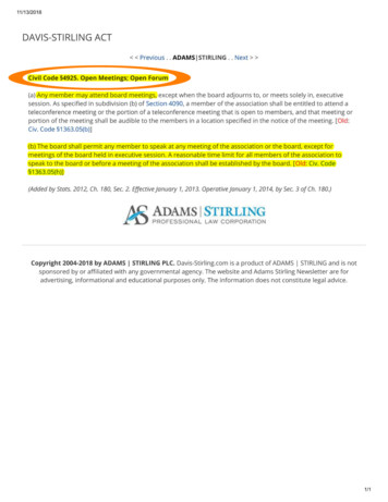
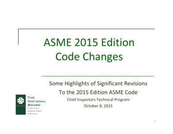
1Chapter 1IntroductionRenewable energy is the cornerstone of humankind’s urgent endeavor to address the climatechange challenge on the technological front. The revolution of fossil energy enabled greatadvances in technology and society, but precipitated calamitous effects on the environment.To continue the pace of growth enabled thus far by plentiful energy, a new revolution willhave to be made toward clean and sustainable sources of power. Such a transition is theinevitable next step in the production of energy - the only question is the magnitude ofaccrued harm before it occurs.To address this challenge, all forms of renewable energy should be explored and developed.Solar photovoltaic and wind power already have achieved a high profile and extraordinaryimprovements in cost and technology. Solar thermal generation has had less development andthe technology is less mature, despite possessing a set of potentially crucial advantages, suchas energy storage, combined heat and power, and potentially low-cost. This dissertation willdiscuss the design and development of a prototype Stirling engine for solar thermal energyconversion.In this research, a full-power single phase Stirling engine prototype was designed, fabricated, and tested. This research builds on previous work in [22] on low-power single andmultiphase prototypes. The primary goals were to demonstrate the technical performanceand feasibility of this Stirling engine technology for use in commercial energy applicationsand to validate the design methodology to provide a path for future development.1.1System DescriptionThe Stirling Engine is the central component of a distributed combined heat and powersystem envisioned in this research. The system as conceived is suitable for residential-scalepower generation and incorporates energy storage to produce consistent output power fromvariable solar resources. The rejected heat from the engine can be used for local heatingneeds, which further improves the total system efficiency.A diagram of the solar thermal system is shown in Figure 1.1. The key components of
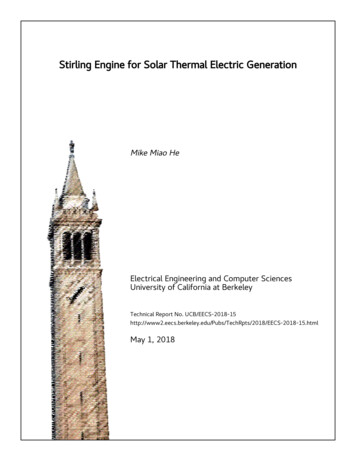
CHAPTER 1. INTRODUCTION2the system include a passive solar collector, a hot thermal storage subsystem, the Stirlingengine described herein, and an optional waste heat capture component. The system is designed with evacuated tube solar collectors in mind, as they provide the highest temperatureinput heat and efficiency of inexpensive commercially available collectors. The collectorsare non-tracking to reduce component count and lower cost, though passive concentratorswere added and tested to improve efficiency. Alternatively, on-site combustion can be usedas a thermal energy source in the absence of, or to balance, solar energy. The thermal energy storage system can be realized with inexpensive hot water tanks that are commonlyused in residiential settings. Additional components include piping, fluid pumps, and heatexchangers for transferring heat between components and streams.The majority of the system is designed to be composable from commercially availablecomponents to reduce cost and for simplicity. The exception to this is the Stirling engine,which requires significant engineering to achieve high performance at low cost. The Stirlingengine is the central component of the system and is the focus of this dissertation.Figure 1.1: System Diagram1.2Stirling Engine BackgroundThe Stirling engine is a heat engine that utilizes the Stirling Cycle to convert thermal energyflux into mechanical energy. The engine can also be run in reverse as a heat pump, whichcauses the inverse conversion. The Stirling Cycle is closed-cycle, which means that theinternal working fluid is retained and isolated from the external energy source. This thenrequires heat exchangers to transfer thermal energy from an external hot-side source intothe engine and from the engine to an external cold-side sink.
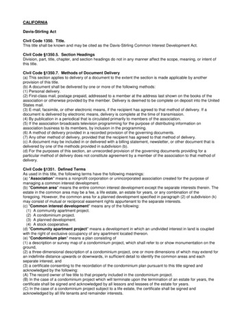
CHAPTER 1. INTRODUCTION3The Stirling Cycle is a thermodynamic cycle, and as such, is limited in efficiency by theCarnot Efficiency, given in Equation 1.1:TC(1.1)THwhere η is the maximum theoretical efficiency, TC is the temperature of the cold-side reservoir, and TH is the temperature of the hot-side reservoir.As a gas cycle, the Stirling Cycle is usefully characterized by a P-V diagram, a plot ofthe internal pressure versus internal volume over a single cycle of the engine. An illustrativeP-V diagram is shown in Figure 1.2.η 1 Figure 1.2: Ideal Stirling Cycle P-V DiagramIn the ideal P-V diagram, the trajectory of the engine is modeled as travelling along fourideal curves. These are shown in Figure 1.2 as a progression from point 1 2 3 4 1.
CHAPTER 1. INTRODUCTION4These four segments can be described as follows. 1 2 is an isometric (equal volume) stepwherein the enthalpy of the internal working fluid is increased by displacing gas through thehot-side heat exchanger and therefore imparting heat from the external high temperaturesource, all while keeping volume constant. The pressure increases during this step due tothe Ideal Gas Law. 2 3 is an isothermal expansion step wherein work is performedby expanding the internal working fluid, typically in a cylinder-piston subsystem. Thetemperature is kept constant by heat exchange with the high temperature source. 3 4 isanother isometric step wherein the enthalpy of the internal working fluid is descreased bydisplacing gas to the engine cold-side, while volume is kept constant. Finally, 4 1 is anisothermal contraction wherein work is performed on the internal working fluid to compressit, typically from the same piston that carried out the expansion earlier.This represents a highly simplified and idealized description of the thermodynamic processes in a Stirling Cycle. In reality, several important deviations from the prior descriptionmust be noted. First, it is vastly more efficient to transfer the enthalpy of the working fluidto a regenerator in step 3 4, which is then returned to the working fluid in step 1 2.The regenerator is an important component of all real Stirling engines and is necessary forachieving high efficiency. Second, the discrete steps outlined are not traversed in disjointtimeframes, rather the real trajectory of the engine will simultaneously undergo two adjacentprocesses at each point in time. This leads to an actual P-V curve that resembles an inscribedellipse within the idealized curves shown in Figure 1.2. Third, the processes themselves arenot ideal; for example, there is no practical implementation of a truly isothermal process. Inreality, that step is more accurately modeled by an adiabatic process, wherein the enthalpyof the working fluid remains constant.Given this description of the Stirling Cycle, the Stirling engine is then a mechanicalembodiment of the cycle. A Stirling engine can be realized in multiple different ways, butthe most common form includes two pistons, hot-side and cold-side chambers and heatexchangers, and a regenerator. One of the pistons is denoted the displacer piston, andis nominally responsible for driving the internal working fluid between the hot and coldchambers during the isometric steps. The other piston is denoted as the power piston, and isnominally responsible for the adiabatic expansion and compression of the working fluid. Thehot and cold chambers and heat exchangers serve to allow thermal flux between the workingfluid and the external hot and cold sources, respectively. The regenerator is responsible forrecapturing enthalpy during one part of the cycle and reimparting that enthalpy back to theworking fluid on the opposite half of the cycle. This configuration is a typical embodimentof a Stirling engine, and is in fact the configuration that was developed in this research. Itshould also be noted that an electric machine is required for conversion between the kineticenergy developed by the engine and electrical energy, and this component is also part of thisresearch.A detailed discussion of the design and characterization of the components, loss terms,and non-idealities will be presented in Chapter 3.
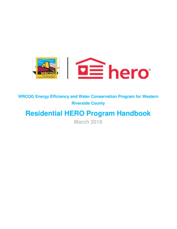
5Chapter 2MotivationThis chapter will discuss the motivation behind this research into Stirling engines for thermal energy conversion. Additional context on renewable energy and energy storage will becovered, and then discuss potential benefits of this research on the field.2.1Broader ContextThe endeavor of transforming the world’s energy portfolio from fossil-fuel generation torenewable generation in order to mitigate climate change is one of the biggest challenges of the21st century. Significant technological and societal advances will need to be made in additionto the extensive progress already achieved. Toward this goal, the Stirling engine systemproposed in this dissertation offers compelling advantages over many other technologies.Over the past decade, renewable energy has undergone a period of rapid growth in technology, cost-competitiveness, and production both domestically and worldwide. Not so longago, renewable energy was considered by many to be prohibitively expensive and impracticalas a bulk solution to clean energy. Since then, wind and solar energy have seen exponentialgrowth in installed capacity and continuous decline in prices. Solar photovoltaics are a compelling example, and are also the most direct comparison to the solar thermal technologyproposed herein.The price of solar photovoltaics has plummeted in recent years, driven by a combinationof growth in silicon production from China, improvements in fabrication and installation ofpanels, and changes in business practices such as aggressive vertical integration in pursuit oflower costs. The median installed price of residential solar panels has dropped from 9.1/Win 2006 to about 4.3/W in 2014, and non-residential solar prices have dropped from 8.8/Win 2006 to 3.9/W for small systems (less than 500kW) and from 7.8/W to 2.8/W for largesystems (greater than 500kW) [3]. Over this same period of time, falling prices have spurredgrowth in annual installed capacity from about 110.8 MW in 2006 to about 2380.8 MW in2014 in the United States alone, with a domestic cumulative capacity of 9392.1 MW [3]. Eventhen, U.S. still ranks fourth in worldwide solar capacity, with Germany, Italy, and China
CHAPTER 2. MOTIVATION6leading. In 2014, worldwide installed capacity reached 178 GW, with 41 GW being added in2014 alone [26], and this growth shows no signs of slowing.Figure 2.1: Solar photovoltaic installed price in the United States [3].Figure 2.2: Solar photovoltaics annual and cumulative installed capacity by year in theUnited States since 1998 [3].With the solar photovoltaic industry already expanding and maturing, it is necessary tomotivate the development of solar thermal energy as a compelling alternative technology.To that end, there are a number of fundamental technological advantages offered by solarthermal technology over solar photovoltaics, chief of which is the ability to easily store energy.The primary energy of renewable sources is fundamentally tied to intermittent and variableprocesses, such as sunlight and wind. As the installed capacity of such renewables grows, sodoes the degree of uncontrollable and unpredictable generation on the grid. The forthcoming
CHAPTER 2. MOTIVATION7need for energy storage has been widely recognized as a counterbalance to this increasingvariability. This energy storage can either come in the form of independent installationsof electrical storage systems, such as batteries and flywheels; or it can be derived fromdeveloping renewable energy sources that are inherently coupled with energy storage, suchas the Stirling engine solar thermal system.Energy storage in a solar thermal system turns an unreliable resource into a reliable sourceof electricity, and does so at low cost, low complexity, and fully integrated into installation.Additionally, solar thermal also carries other important benefits, including the simplicity ofcomponents and conventionality of fabrication, which would aid in cost-competitiveness andbypassing production bottlenecks and supply chain issues; the potential for combined heatand power, which could significantly increase overall thermal efficiency; and application as adistributed generation system, fulfilling a role not available to technologies that rely on thescale of centralized installations. These motivations will be discussed in further detail.Energy StorageAs renewable energy achieves higher penetration on the modern electric grid, the intermittency and variability in solar and wind energy become a more significant challenge thatmust be addressed by the industry. The underlying operation of the electric grid relies oninstantaneously fulfilling demand with regulated generation. The addition of large amountsof uncontrollable generation serves to break this contract, upending the way that the gridhas operated since the beginning. A certain amount of control must be present in the gridto maintain stability, so this gives rise to two fundamentally different but complementaryapproaches to integrating renewables.The first is to add controllable compensation on the supply side in the form of energystorage or responsive fossil fuel generation. This addresses the challenge while serving tokeep the existing structure of supply-side control intact - good energy storage would beinvisible to the consumer. The second approach is to add controllability and responsivenessto the demand side of the grid. This has the advantage of utilizing the existing untappedflexibility of the demand side to perform the same function of balancing supply and demand,but challenges the entrenched paradigm of supply side control, and requires the introductionof pervasive intelligence and actuation on the demand side[11].Most likely, both energy storage and controllable demand will be employed to aid in theprocess of renewable integration. The Stirling engine system as envisioned is potentially amixture of these two approaches. It incorporates energy storage to produce reliable powergeneration, but since it is a distributed system designed to be co-located with demand, itcan also autonomously balance load on the demand side. This carries advantages over eitherapproach employed independently - the storage available can balance both local generationand demand simultaneously. The technology is also attractive simply due to the fact thatit is generation with built-in storage. This enables grid integration with minimal effect ongrid stability.
CHAPTER 2. MOTIVATION8The energy storage potential of the Stirling engine system is a major compelling featurewhen compared to photovoltaic solar, and dramatically improves its competitiveness. Theoverall necessity for more storage is unequivocal and unambiguous in the industry, andit is quickly moving to incentivize and demand installation of storage. Examples includemandates for rapid expansion of energy storage capacities, such as California’s AB 2514,which as directed by the CPUC will mandate procurement of 1,325 MW of energy storagecapacity by the year 2020 [27], which almost doubles worldwide non-hydro storage [24] andis over 50 times California’s current installed storage capacity [25].A Stirling-engine based thermal system contributes in two ways to the storage challenge.First, as a generation technology, its power output is reliable and consistent, presentingit as a technology that does not require additional balancing from storage. Indeed, it isflexible and controllable in its power output, both on short time scales of seconds by varyingthe frequency of the engine, or on longer time scales of minutes to hours by varying inputthermal energy. Second, the Stirling engine process is reversible, allowing it to be used asa pure energy storage mechanism by driving it in heat pump mode from grid energy, thenlater discharging stored energy in generation mode. In general, deriving a specific monetaryvalue from these advantages is difficult, depending on a number of factors including marketstructure, composition of generation sources, load profiles, and factors particular to a region.As a reference, NREL estimates that the value of electricity from a utility scale solar thermalis 2.57 times that of electricity from a solar photovoltaic plant given a 40% RenewablePortfolio Standard [15]. This comparison probably cannot be extrapolated directly to theStirling engine system, but points toward a significant value in reliable generation.The energy storage market for non-hydro technologies is still relatively young and growing. Energy storage mandates in the public sphere have been typically agnostic of technologies, leaving room for a system such as the Stirling engine solar thermal system toparticipate. However, typical market structures do not easily accomodate or incentivizea distributed storage and generation technology such as this one. Renewable generation,such as photovoltaics, have mandated incentive structures, such as net metering, that donot provide additional incentives for the reliability of the source, hindering the ability of theconsumer to capture the value of storage. However, there are signs that this market structureis changing in recognition of the costs and challenges of the ever-growing share of renewablegeneration. For instance, PG&E is offering an incentive of up to 1.31/W for generationinstallations that have energy storage included [7]. Net metering programs have also facedsignificant challenges in recent years across multiple states, such as Nevada, Maine, Arizona,Hawaii, and California, partly as response to the hidden costs of providing a reliable gridwhen distributed PV is incentivized with retail electricity rates. A Stirling engine solar thermal system could alleviate some of these tensions between utilities and solar developers byintroducing ubiquitous energy storage along with the generation capacity.One challenge is that monetization of the energy storage component of the Stirling enginesystem, apart from just providing firm capacity, is difficult in the current market structure.Energy storage is typically procured in the form of large centralized installations, and participates in markets in order to sell storage services such as regulation, load balancing, and
CHAPTER 2. MOTIVATION9reserves. Behind-the-meter energy storage is starting to gain some presence, especially sinceAB 25
This dissertation discusses the design, fabrication, and testing of a Stirling engine as the key component in a solar thermal electric system. In particular, the design addresses the low temperature di erential that is attainable with distributed solar with low concentration ratios and is des