Transcription
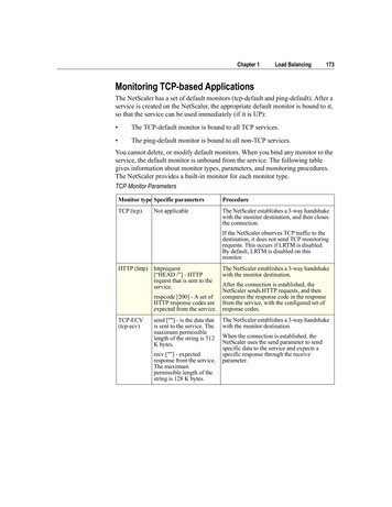
Chapter 1Load Balancing173Monitoring TCP-based ApplicationsThe NetScaler has a set of default monitors (tcp-default and ping-default). After aservice is created on the NetScaler, the appropriate default monitor is bound to it,so that the service can be used immediately (if it is UP): The TCP-default monitor is bound to all TCP services. The ping-default monitor is bound to all non-TCP services.You cannot delete, or modify default monitors. When you bind any monitor to theservice, the default monitor is unbound from the service. The following tablegives information about monitor types, parameters, and monitoring procedures.The NetScaler provides a built-in monitor for each monitor type.TCP Monitor ParametersMonitor type Specific parametersProcedureTCP (tcp)The NetScaler establishes a 3-way handshakewith the monitor destination, and then closesthe connection.Not applicableIf the NetScaler observes TCP traffic to thedestination, it does not send TCP monitoringrequests. This occurs if LRTM is disabled.By default, LRTM is disabled on thismonitor.HTTP (http) httprequest[“HEAD /”] - HTTPrequest that is sent to theservice.The NetScaler establishes a 3-way handshakewith the monitor destination.After the connection is established, theNetScaler sends HTTP requests, and thenrespcode [200] - A set ofcompares the response code in the responseHTTP response codes are from the service, with the configured set ofexpected from the service. response codes.TCP-ECV(tcp-ecv)send [""] - is the data thatis sent to the service. Themaximum permissiblelength of the string is 512K bytes.recv [""] - expectedresponse from the service.The maximumpermissible length of thestring is 128 K bytes.The NetScaler establishes a 3-way handshakewith the monitor destination.When the connection is established, theNetScaler uses the send parameter to sendspecific data to the service and expects aspecific response through the receiveparameter.
174Citrix NetScaler Traffic Management GuideTCP Monitor ParametersMonitor type Specific parametersProcedureHTTP-ECV(http-ecv)send [""] - HTTP data issent to the serviceThe NetScaler establishes a 3-way handshakewith the monitor destination.recv [""] - the expectedHTTP response data fromthe serviceWhen the connection is established, theNetScaler uses the send parameter to send theHTTP data to the service and expects theHTTP response that the receive parameterspecifies. (HTTP body part without includingHTTP headers).Empty response data matches any response.Expected data may be anywhere in the first24K bytes of the HTTP body of the response.UDP-ECV(udp-ecv)send [""] - data that is sentto the service.recv [""] - expectedresponse from the service.When the receive string is specified:If the response matches the receive string, theservice is marked as up.Consequently, if the response matches thereceive string for a reverse monitor, theservice is marked as down.Also, the service is marked as down if an“icmp port unreachable” message is received.When the receive string is not specified:A service is marked as up whether or not aresponse is received. However, the service ismarked as down if an “icmp portunreachable” message is received. ForLRTM monitors, when no response isreceived, the response time is the responsetime-out for the monitor.When the UDP monitors detect an ICMP portunreachable error, the service is marked asdown immediately.PING (ping) Not ApplicableThe NetScaler sends an ICMP echo requestto the destination of the monitor and expectsan ICMP echo response.To configure built-in monitors for TCP-based applications, see “ConfiguringMonitors in a Load Balancing Setup,” on page 162. To create a monitor, you mustprovide values for the required parameters.Monitoring SSL ServicesThe monitors periodically check the SSL servers. The NetScaler has four built-insecure monitors: TCPS, HTTPS, TCPS-ENV, and HTTPS-ENV. You can use thesecure monitors to check the HTTP and non-HTTP traffic. The secure monitorswork as follows:
Chapter 1Load Balancing175TCPS - the NetScaler establishes a TCP connection. After the connection isestablished, the NetScaler performs an SSL handshake with the server. After thehandshake is over, the NetScaler closes the connection.HTTPS - the NetScaler establishes a TCP connection. After the connection isestablished, the NetScaler performs an SSL handshake with the server. When theSSL connection is established, the NetScaler sends HTTP requests over theencrypted channel and checks the response codes.TCPS-ECV - the NetScaler establishes a TCP connection. After the connectionis established, the NetScaler performs SSL handshake with the server. When theSSL connection is established, the NetScaler sends specific data using the sendparameter to the service on the encrypted channel and expects a specificencrypted response. The response is decrypted, and the data is verified throughthe receive parameter.HTTPS-ECV - the NetScaler establishes a TCP connection. After the connectionis established, the NetScaler performs an SSL handshake. When the SSLconnection is established, the NetScaler sends the encrypted HTTP requestspecified using the send parameter to the service and expects the encrypted HTTPresponse (HTTP body part, not including HTTP headers). This response isdecrypted and compared with the expected response specified using the receiveparameter. The following table describes the monitor types for monitoring SSLservices.SSL Service Monitor ParametersMonitor typeProbeSuccess criteria (Direct condition)TCPTCP connectionSuccessful TCP connection establishedand successful SSL handshake.SSL handshakeHTTPTCP connectionSSL handshakeEncrypted HTTP requestTCP-ECVTCP connectionSSL handshakeData sent to a server isencryptedHTTP-ECVTCP connectionSSL handshakeEncrypted HTTP requestSuccessful TCP connection is established,successful SSL handshake is performed,and expected HTTP response code inserver HTTP response is encrypted.Successful TCP connection is established,successful SSL handshake is performed,and expected TCP data is received fromthe server.Successful TCP connection is established,successful SSL handshake is performed,and expected HTTP data is received fromthe server.To configure built-in monitors to check the state of SSL services, see“Configuring Monitors in a Load Balancing Setup,” on page 162. You mustprovide values for the required parameters to create monitors.
176Citrix NetScaler Traffic Management GuideMonitoring FTP ServicesThe FTP monitor opens a connection to an FTP server to determine the state ofthe service. During an FTP session, two connections are opened between the FTPmonitor and FTP server: The FTP monitor opens the control connection totransfer commands between the monitor and the FTP server. Then the FTP serveropens the data connection to transfer files between the FTP monitor and theserver. The FTP monitor connects to the FTP server, checks the response code,and sends a command to the FTP server. If the FTP monitor receives a response inthe specified time, the FTP services are marked up. The NetScaler establishes aTCP connection to the service. After a connection is established, the NetScalerlogs on to the FTP server using the specified user name and password. To monitorFTP services, use the parameters as described in the following table.FTP Monitor ParametersParameterSpecifiesUser NameUser name used in the probe.(userName)PasswordPassword used in monitoring.(password)The NetScaler has a monitor of type FTP-EXTENDED that provides a script tothe FTP server. The FTP server executes the script and then responds to the query.Using the response, the FTP-EXTENDED monitor determines the state of theservice. The following table describes the parameter you must use to configureFTP - EXTENDED monitors.FTP-Extended Monitor ParametersParameterSpecifiesFile NameFile name to be used for FTP-EXTENDED monitor.(fileName)To configure built-in monitors to check the state of FTP services, see“Configuring Monitors in a Load Balancing Setup,” on page 162. You mustprovide values for the required parameters to create monitors of type FTP or FTP- EXTENDED.Monitoring SIP ServicesThe Session Initiation Protocol (SIP) is an application layer control protocolestablished by the Internet Engineering Task Force (IETF). It is designed toinitiate, manage, and terminate multimedia communications sessions and hasemerged as the standard for Internet telephony (VoIP).
Chapter 1Load Balancing177SIP messages can be transmitted over TCP or UDP. SIP messages are of twotypes: request messages and response messages. The following table summarizesthe formats of these messages.SIP Monitor ParametersMessage typeComponentsDetailsRequestMethodInvite, Ack, Options, Bye, Cancel, RegisterRequest URIRepresents the subject, media type, or urgency ofsessions initiated. The common format ersSIP versionThe SIP version being usedSIP versionThe SIP version being usedStatus codeA 3-digit integer result code. The possible valuesare:Response1xx: Information Responses. For example: 180,Ringing2xx: Successful Responses. For example: 200, OK3xx: Redirection Responses. For example: 302,Moved Temporarily4xx: Request Failures Responses. For example:403, Forbidden5xx: Server Failure Responses. For example: 504,Gateway Time-out6xx: Global Failure Responses. For example: 600,Busy EverywhereReason-phraseTextual description of the status codeThe traffic in an SIP-based communication system is routed through dedicateddevices and applications (entities). In a multimedia communication session, theseentities exchange messages.
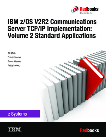
178Citrix NetScaler Traffic Management GuideOne of the most common scenarios for SIP is VoIP, where SIP is used to set upthe session. The usage scenario described in the following section illustrates therole of the messages and entities in an SIP-based communication system.SIP mechanismUser agent (UA) is the entity that initiates the call. The user agent can be an SIPsoftphone (a PC-based application), or an SIP phone.To initiate a call, the user agent sends an INVITE request to the previouslyconfigured SIP proxy server. The INVITE request contains the details of thedestination, such as the destination uniform resource identifier (URI) and Call ID.In the diagram, the Caller A (user agent) sends an INVITE request to Proxy A.When the proxy server receives the INVITE request, it sends a 100 (Trying)response to the user agent that initiated the Caller A. It also performs a DNSlookup to locate the SIP proxy server of the destination domain. After the SIPproxy server of the destination domain is located, the SIP proxy at the sourcedomain sends the INVITE request to it. Here, Proxy A sends a 100 (Trying)response to Caller A and an INVITE request to Proxy B.When the SIP proxy server of the destination domain receives the INVITErequest from the SIP proxy server of the source domain, it responds with a 100(Trying) response. It then sends the INVITE request to the destination user agent.In this case, Proxy B sends a 100 (Trying) response to Proxy A and an INVITErequest to Caller B.
Chapter 1Load Balancing179When the destination user agent receives the INVITE request, it alerts Caller Band responds with a 180 (ringing) response. This response is routed back to thesource user agent through the proxies.When caller B accepts the call, the destination user agent responds with a 200(OK) response. This signifies that caller B has answered the call. This response isrouted back to the source user agent through the proxies. After the call is set up,the user agents communicate directly without the proxies.The following table describes the entities of an SIP-based communication systemand their roles.SIP System EntitiesEntityRoleUser Agent (UA)SIP user agents generate requests and respond to incomingrequests. A user agent that generates requests is known as aUser Agent Client (UAC). The user agent that responds torequests is known as the User Agent Server (UAS). In thepreceding example, Caller A was the UAC and Caller B wasthe UAS.Proxy ServerProxies receive and route SIP requests based on the URI.They can selectively rewrite parts of the request messagebefore forwarding it. They also handle registrations,invitations to user agents, and apply call policies.Redirect ServerRedirect servers send routing information to the SIP proxyservers.Registrar ServerRegistrar servers provide location information to user agentsand proxy servers.Back-to-Back UserAgent (B2BUA)Back-to-Back User Agents (B2BUA) are combination ofUAS and UAC.You can configure the NetScaler to load balance SIP requests to a group of SIPproxy servers. To do this, you need to create an LB vserver with the LB methodset to Call-ID hash, and then bind to it the services representing the SIP proxies.You must configure the SIP proxies so that they do not add private IP addresses orprivate domains to the SIP header/payload. SIP proxies must add a domain nameto the SIP header that resolves to the IP address of the SIP vserver. Also, the SIPproxies must communicate with a common database to share registrationinformation.
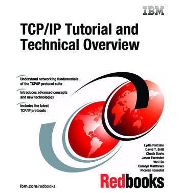
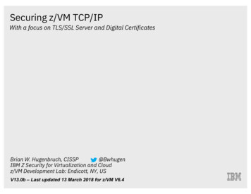
180Citrix NetScaler Traffic Management GuideThis section describes the role of the NetScaler when configured to perform SIPload balancing in the two most commonly used topologies: One-arm DSR mode Inline DSR modeFor more information about DSR mode, see the section “Configuring LoadBalancing in Direct Server Return Mode,” on page 253.Understanding SIP in One-arm DSR ModeIn direct server return (DSR) mode, the NetScaler receives SIP requests from theuser agents, and routes the requests to the appropriate SIP proxy using the LBmethod. The SIP proxies send the responses to the destination SIP proxies,bypassing the NetScaler as illustrated in the following diagram.SIP in one-arm modeThe flow of requests and responses in this scenario is as follows:1.The user agent, Caller A, sends an INVITE request to the NetScaler. TheNetScaler, using the LB method, routes the request to Proxy 2.2.Proxy 2 receives the INVITE request from the NetScaler and responds witha 100 (Trying) message.3.Proxy 2 performs a DNS lookup to obtain the IP address of the destinationSIP proxy at domainB.com. It then sends the INVITE request to thedestination proxy.4.The destination proxy responds with a 100 (Trying) message and sends theINVITE request to the destination user agent, Caller B. The destination useragent, Caller B, begins to ring and responds with a 180 (Ringing) message.
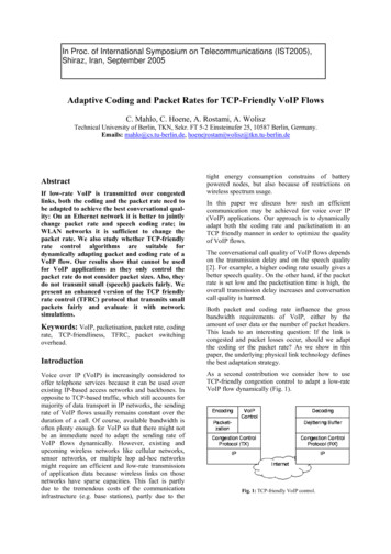
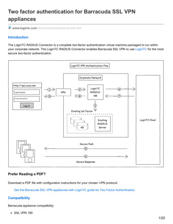
Chapter 1Load Balancing181This message is sent to Caller A through the NetScaler and the Proxy 2.After the user accepts the call, Caller B responds with a 200 (OK) messagethat is propagated to Caller A through the NetScaler and the Proxy 2.5.After Caller B accepts the call, the user agents (Caller A and Caller B)communicate independently.Understanding SIP in Inline DSR ModeIn inline DSR mode, the NetScaler is placed between the router and the SIPproxy, as illustrated in the following diagram.SIP in inline modeThe flow of requests and responses is as follows:1.The user agent, Caller A, sends an INVITE request to the NetScaler. TheNetScaler, based on the LB method, routes the request to Proxy 2.2.Proxy 2 receives the INVITE request from the NetScaler and responds witha 100 (Trying) message.3.Proxy 2 performs a DNS lookup to obtain the IP address of the destinationSIP proxy at domainb.com. It then propagates the INVITE request to thedestination proxy through the NetScaler.4.The NetScaler performs RNAT, and replaces the source IP address in theINVITE request with the NAT IP address, and then forwards the INVITErequest to the destination SIP proxy.
182Citrix NetScaler Traffic Management Guide5.The destination proxy responds with a 100 (Trying) message and sends theINVITE request to the destination user agent, Caller B. Caller B, begins toring and responds with a 180 (Ringing) message. This message is sent toCaller A through the NetScaler and the Proxy 2. After the user accepts thecall, Caller B responds with a 200 (OK) message that is propagated toCaller A through the NetScaler and the Proxy 2.6.After the user accepts the call, the user agents (Caller A and Caller B)communicate independently.To monitor SIP services, use the parameters as described in the following table.SIP Service ParametersParameterSpecifiesMaximum ForwardsSIP packet max-forwards. Default value: 1 Minimumvalue: 0 Maximum value: 255.(maxForwards)SIP Method(sipMethod)SIP URI(sipURI)SIP Register URISIP method to be used for the query. Possible values:OPTIONS, INVITE, REGISTER Default value:OPTIONS.SIP method string, sent to the server. For example“OPTIONS sip:sip.test.”SIP user to be registered.(sipregURI)To configure built-in monitors to check the state of SIP server, see “ConfiguringMonitors in a Load Balancing Setup,” on page 162. You must provide values forthe required parameters to create a monitor of type SIP.Monitoring RADIUS ServicesThe RADIUS monitor periodically checks the state of the RADIUS server usingthe RADIUS protocol. The NetScaler sends the RADIUS packets to the RADIUSserver. The RADIUS server authenticates the RADIUS clients using theauthentication information in the RADIUS database. Based on the authentication,the RADIUS server sends the response to the NetScaler. The following are theexpected responses from the RADIUS server: If the client and the server have a similar configuration, the server mustsend an Access-Accept response. The response code for Access-Accept is2. This is the default code that the NetScaler uses. If there is a mismatch in the user name, password, or secret key, the serversends an Access-Reject response. The response code for Access-Reject is 3.
Chapter 1Load Balancing183To monitor RADIUS services, use the parameters as described in the followingtable.RADIUS Service ParametersParameterSpecifiesUser NameUser name on theRADIUS/NNTP/FTP/FTP-EXTENDED/MYSQL/POP3server. This user name is used in the probe.(userName)Password(password)RADIUS Key(radKey)RADIUS NAS ID(radNASid)RADIUS NA SIP(radNASip)Password used in monitoring RADIUS/NNTP/FTP/FTP-EXTENDED/MYSQL/POP3/LDAP servers.Shared secret key value that the RADIUS server usesduring client authentication.NAS-ID that is encapsulated in the payload when anaccess request is made.The IP address that is encapsulated in the payload when anaccess-request is made. When radNASip is notconfigured, the NetScaler sends the mapped IP address(MIP) to the RADIUS server as the NAS IP address.You must perform the following configurations in the RADIUS server:1.Add the user name and password of the client to the database where theRADIUS daemon searches for authentication.2.Add the IP address and secret key of the client to the respective RADIUSdatabase.3.Add the IP addresses that originate from the RADIUS packets to theRADIUS database. If the NetScaler has more than one mapped IP address,or if subnet IP address (SNIP) is used, you must add the same secret key forall of the IP addresses. If the client IP address is not added into thedatabase, the server discards the packets.The RADIUS server can send an access-reject response for any mismatch in username, password, or secret key. To configure built-in monitors to check the state ofRADIUS server, see “Configuring Monitors in a Load Balancing Setup,” on page162. You must provide values for the required parameters to create a monitor oftype RADIUS.Monitoring DNS and DNS-TCP ServicesThe Domain Name System (DNS) monitors use the DNS protocol to determinethe state of the DNS server. The DNS monitor sends a DNS query to the serverthat resolves the query to an IPv4 or IPv6 address. The resolved IP address is thenchecked against the list of previously configured IP addresses. The IP address listcan contain a maximum of five IP addresses.
184Citrix NetScaler Traffic Management GuideIf the resolved IP address matches at least one of the IP addresses in the IPaddress list, the DNS service is m
monitor and FTP server: The FTP monitor opens the control connection to transfer commands between the monitor and the FTP server. Then the FTP server opens the data connection to transfer files between the FTP monitor and the server. The FTP monitor connects to the FTP server, checks