Transcription
Manuals User Manuals Simplified.TYCON TPDIN-Monitor-WEB3 User GuideDecember 1, 2021December 2, 2021Home » TYCON » TYCON TPDIN-Monitor-WEB3 User GuideContents [ hide1234567TYCON TPDIN-Monitor-WEB3Qwik InstallConnector PinoutsSpecificationsTypical ApplicationLimited WarrantyDocuments / Resources7.1 Related Manuals /ResourcesTYCON TPDIN-Monitor-WEB3Remote Power StationsBackup Power SystemsSolar SystemsWind Powered SystemsIndustrial Sense & ControlProcess AutomationCongratulations! on your purchase of the TPDIN-Monitor-WEB3 System Monitor. Please take a moment to review this Qwik In-stall Guide before installation.Recommended Tools and Supplies: Small Flat Blade Screwdriv-er, 35mm x 7.5mm DIN RailImportant!: Before you get started, please go to sup-port.tyconsystems.com, download the latest firmware for your particular model and upgrade the unit.
Security: Please be sure to set a username and password on the Network page to secure the user interface. Also set your own Telnet username/passwordand enable Telnet so that you can reboot the unit remotely in case of a browser access issue.Qwik InstallSTEP 0: The TPDIN-Monitor-WEB3 can be used to monitor Qty 4 1V-80V Voltages, four Currents ( Qty 1 /- 10A, Qty 1 shunt and Qty 2 20A) and twotemperatures (1 internal and 1 external). There are four 10A relays that can be used to control power to four devices. Two of the relays (CH1,CH2) arenormally closed type and two are normally open type (CH3,CH4). They can be automatically controlled by voltage, cur-rent, temperature, ping watchdog ortime.NOTE: There is an RS232/485 input for interfacing to Tycon MPPT so-lar controllers. If connected to the Tycon MPPT solar controller, all sys-temparameters such as PV volts, PV current, Battery Volts, Battery Current, Load Volts and Load Current are accessible via the WEB3.STEP 1: Install the TPDIN to a suitable DIN rail mount.STEP 2: Connect the voltages to be monitored to the V1 to V4 voltage ports. Voltages between 1 and 80volts DC can be monitored.STEP 3: Connect the currents to be monitored to the I1-I3 current ports. I1 and I2 can read currents from 0.1 to 20A. I3 can read positive or negativecurrents to /-10A. I3 can be used to measure current flow-ing into and out of a battery to see if the battery is charging or discharg-ing. I4 is designed to beused with a current shunt to be able to read higher currents. It is also capable of reading /- current.STEP 4: Connect any power to devices you want to be under relay con-trol to the CHI—CH4 10A relays. The CH1 and CH2 relays are normally closedrelays and the CH3 and CH4 are normally open relays. When the relay is in it’s default position it draws zero power. When it is switched to the oppositeposition, it draws up to 0.5W. When the Open/Closed indicator in the user interface is Green, the relay is not using any power. When it is Red, the relay isusing up to 0.5W.STEP 5: Connect the External Temperature sensor to the included green wire terminal connector. There is no polarity. Plug the wire termi-nal connector tothe “Temp.” connector location. Locate the external temperature sensor where you want to measure external temperatures. You can extend the wire lengthsif desired by soldering additional wires to the existing wires. You can measure temperatures from –40C to 125CSTEP 6: The TPDIN-Monitor-WEB3 can be powered with 10-57VDC thru the wire terminal connector #7 or via 802.3af/at PoE or Passive 24V to 48V PoEthru the RJ45 PoE/DATA port. If powered by both wire terminal and PoE port, the port with highest voltage has priority.Important!: Tycon recommends using shielded CAT5/6 cable to connect to the RJ45 port on the WEB3. This will ensure proper grounding of the port.STEP 7: Download the Java based Discovery Tool from sup- port.tyconsystems.com. Your computer must have java installed to use the discovery tool(java.com).The WEB3 ships with IP addressing by DHCP enabled. The discovery tool will find the IP address of the device so you can access the web control panel. Ifnot connected to a DHCP server the default IP address is 192.168.1.6STEP 8: Open the Web control panel of the unit by using the discovery tool or typing the units known IP address into a browser. The unit will serve up theMonitor web page. The monitor page is where all the volt-age, current, temperature and relay status can be seen. Relays can also be controlled manuallyfrom this page. There is a cycle button by the relays if you want to automatically cycle a relay from open to closed and back. The Cycle Delay is specified onthe SYSTEM page.You can modify any labels directly on the monitor page. Click “Save Labels” to save your customizations.STEP 9: Open the System Page. Here you can set a static IP Address. You can also set access security by entering a user name and pass-word (10characters max). You can also set a unique Host Name to identify the Monitor. Sensor offsets can be entered to fine tune the readings to match anotherpiece of measuring equipment or to compen-sate for line loss.STEP 10: Open the Relays Page. This is where you can set the relay controls. Relays can be controlled by Time, Temp, Voltage, Current, Ping or Periodic.The controls can be setup as compound controls so more than 1 control can be setup for a single relay. The control above has priority.STEP 11: Open the Email Page. This is where you can setup the SMTP server. The WEB3 supports unencrypted (Port 25) and TLS (Port 587). Gmailsecurity requires 2-step verification. You need to get and use an app password from your Gmail account.STEP 12: Open the Alerts Page. This is where you can setup multiple email alerts. An alert will be sent when the measurement is outside the min/maxwindow.Other PagesNetwork: On this page you setup the network parameters and pass-words. Set DHCP or static addressing. If using static IP, be sure to set a valid gatewayand DNS or else the email alerts won’t work. Set a username and password to secure the web interface. Set your own username and password for Telnetand enable Telnet. Telnet will allow you to reboot the unit in case there is some problem accessing the unit through a web browser.SNMP: You setup the SNMP access on this page. The unit supports SNMP walking and extracting data via SNMP programs such as Cacti. The relays canalso be controlled via SNMP. The unit does not support SNMP traps.Upgrade: Go to this page to update the firmware. Download the latest firmware from Tyconsystems.com/support/firmware. Select the down-loaded file andclick on “Upgrade and Reboot”. Note: Do not navigate away from this page during upgrade or the upgrade will be aborted.Log: You will find a sequential log file of system events here. You can set the log interval on the System page. The log memory status can be seen on theMonitor Page. When the memory reaches 100% the new data will bump the old data. The log holds 4048 records.Graph: You can graph single or multiple parameters. Click on “Show All” to see all the data. To print the graph do a screen capture and save as a graphicfile.MPPT: This is where you can see the data from a connected Tycon MPPT solar controller. The data will also be added to the log file. You can also togglethe load connected to the solar controller on/off.TECH CORNERAdditional Information you may find useful1. FUSE: The TPDIN-Monitor-WEB3 has an external mini blade 2A fuse. If the WEB3 doesn’t power up, check the fuse.2. LIMITS: Don’t exceed 80V on the voltage inputs or 20A on the cur-rent inputs or 10A on the relays or the unit could be damaged. This kind of damageisn’t covered under warranty.3. MOISTURE: The WEB3 is designed to be used indoors or out-doors in a weatherproof enclosure. Avoid getting the WEB3 wet. This kind of damageisn’t covered under warranty.4. TELNET: The unit can be accessed via TELNET to see the pre-sent readings and also control the relays. You can toggle relays using the number keyson the computer #1-4. You can also reboot the unit by typing “r”. Default TELNET user name admin and password tycon
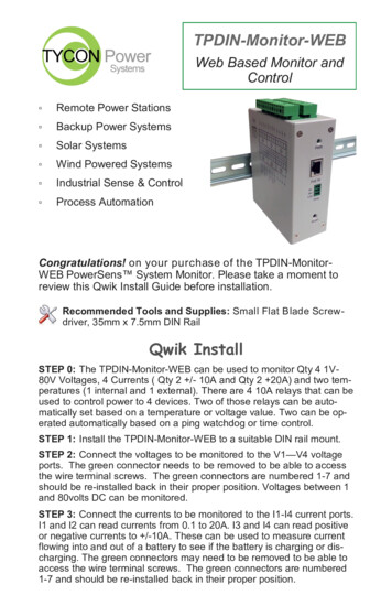
5. BATTERY STATUS: If measuring voltage of battery systems typi-cal state of charge readings are as follows. These readings are without any load onthe battery. For max battery life don’t discharge under 50%:State OfChargeSealed orFlooded LeadAcidGEL BatteryAGM Battery100%12.7 Volts12.9 Volts12.8 Volts75%12.4 Volts12.7 Volts12.6 Volts50%12.2 Volts12.4 Volts12.3 Volts25%12.0 Volts12.0 Volts12.0 Volts10%11.8 Volts11.8 Volts11.8 Volts6. Operating Power: The TPDIN-Monitor-WEB3 has extremely low operating power, typically less than 1.5W. CH1,CH2 relays are nor-mally closed type andCH3,CH4 are normally open type so in typi-cal operation they don’t use any power until they are energized. If the relays are turned on, the power usage willincrease by 0.5W per relay.Connector PinoutsSpecificationsVoltage Measurement (DC)V1, V2, V3, V4 1-80VDCVoltage Meas Accuracy /- 0.1VI1, I2 0.1A to 15A (20A Peak), I3 /-10ACurrent Measurement (DC)I4 Supports Ext Current Shunts – Input Range /25mVCurrent Meas Accuracy /- 0.1ACommon Mode Volt Range-20V to 80V
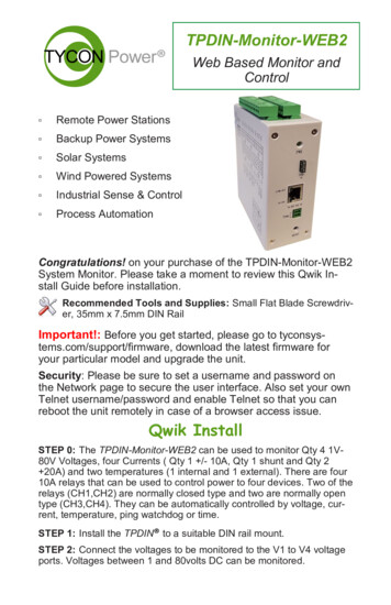
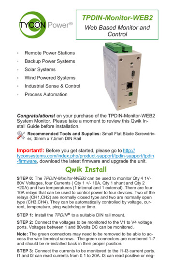
Temperature MeasurementT1,T2 -40C to 125CTemp Measurement TypeT2 Embedded, T1 External Sensor (included)Temp Measurement Accuracy /- 1 degCRelaysCH1, CH2 (NC) ; CH3, CH4 (NO) 10A 30VDC,125-250VACRelay ControlCH1, CH2, CH3, CH4 Manual or Automatic basedon Volts, Amps, Temperature, Ping or Time10-57VDC Wire Terminal orPower Requirements802.3af/at Class 0 PoE or 24V Passive PoE 1.5W AllRelays Off, 3.5W All Relays OnAccessibilityVia Web Browser and SNMP and TelnetData-LoggerFIFO, Max 4048 data sets, Prog log intervalConnectionsRemovable Wire TerminalWire Size12AWG MaxMountingDIN RailOperating Temperature-40C to 75C (-40F to 167F)Humidity (RH)0% – 90%Dimensions (LxWxH)125 x 102 x 46mm (4.9” x 4” x 1.8”)Weight410g (14.5 oz)Warranty3 YearsTypical Application
7. WIRE TYPE: When using the monitor in high current applications ( 10A), it’s important to use a 10-12AWG stranded wire with many fine strands. Thistype of wire will provide a low resistance electrical connection to the green connectors. If using coarse strand wire such as THHN, there will be higherresistance in the connection which will generate excessive heat at high currents, possibly caus-ing damage to the connectors. NEC Wire Class C and D areac-ceptable.8. Reset to Factory Defaults: Power up unit. Wait at least 20 sec-onds. Press reset button and hold for 10 seconds to reset to factory defaults. If reset buttonis held for longer than 30 seconds, the unit will roll back to the last stable factory firmware. Only use this if the unit has an unrecoverable error.9. Shunt Resistor: The unit is capable of reading a shunt voltage up to /-25mV into I4 input. Just enter the shunt resistor ohms on the system page and thecorrect current will be displayed on the monitor page.10. Branding: You can brand the TPDIN-Monitor-WEB3 with your own logo, colors and suppress the Tycon footer. Just access the cus-tom.htm page byentering IP Address /custom.htm in a browser. You can change the parameters on this page and save. If you have multiple units to update with yourbrand, get the branding correct on one unit then go to the brand.htm page. Copy and paste the code to a txt file. Open the next unit brand.htm page andupload the new text file to the unit. All custom parameters will be uploaded from the sin-gle file.11. Modbus Serial Interface to Tycon MPPT Solar ControllersInterface Cable PNTycon MPPT Model NumberTPDIN-CABLE-232TP-SC24-20N-MPPT TP-SC24-40NMPPT TP-SC48-60-MPPTTPDIN-CABLE-485TP-SC24-30N-MPPT TP-SC24-60NMPPT TP-SC48-60P-MPPT
Limited WarrantyThe TPDIN products are supplied with a limited 36 month warranty which covers material and workmanship defects. This warranty does not cover thefollowing:Parts requiring replacement due to improper installation, misuse, poor site conditions, faulty power, etc.Lightning or weather damage.Physical damage to the external & internal parts.Products that have been altered, or defaced.Products that have been subjected to voltages or currents greater than the published ratings.Water damage for units that were not mounted according to user manual.Usage other than in accordance with instructions and the normal intended use.Notes8000084 Rev 2 TPDIN-Monitor-WEB3 Qwik Install GuideDocuments / ResourcesTYCON TPDIN-Monitor-WEB3 [pdf] User GuideTYCON, TPDIN, Monitor, WEB3, Web Based Monitor and Control, Web Based Monitor and, ControlRelated Manuals / ResourcesAUSTRALIAN MONITOR XRS10 Loudspeaker Installation GuideAUSTRALIAN MONITOR XRS10 Loudspeaker XRS10 INSTALLATION XRS12 INSTALLATIONwww.australianmonitor.com.auDELL E2722H 27 inch Monitor User GuideE2722H www.dell.com/E2722H Dell P/N: XXMJP Rev. A00 52021-08 2021 Dell Inc. or itssubsidiaries.DELL E2222H FHD Computer Monitor User GuideE2222H1 2 3 4 5 6 www.dell.com/E2222H PHILIPS 271V8 LCD Monitor User ManualV Line/i Line / line 271V8/272V8/271i8 Quick Start Register your product and get support atwww.philips.com/welcome Need help? Online Manuals ,homeprivacy
The discovery tool will find the IP address of the device so you can access the web control panel. If not connected to a DHCP server the default IP address is 192.168.1.6 STEP 8: Open the Web control panel of the unit by using the discovery tool or typing the units known IP address into a browser. The unit will serve up the Monitor web page.