Transcription
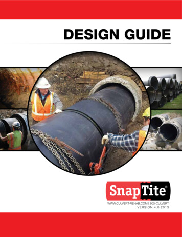
DRAINAGE FACILITIESApril 2011501 PIPE CULVERT AND STORM DRAINS501 1 DescriptionSeveral types of pipe are used for storm drain and culvert applications. They are:·····Precast Concrete Pipeincludes: RCP or RGRCP (Rubber Gasket) Reinforced Concrete PipeNRCP Non Reinforced Concrete Pipe (up to 24”)HERCP Horizontal Elliptical Reinforced Concrete PipeRCB Reinforced Concrete BoxCorrugated Metal Pipe (CMP)includes: Corrugated Steel Pipe (CSP)Corrugated Aluminum Pipe (CAP)Plate Arch (see section 502)also includes slotted drains and perforated pipesBlack Steel Pipe (BSP)Corrugated High Density Polyethylene Plastic Pipe (CHDPEPP)Non Reinforced Cast In Place Concrete Pipe (NRCIPCP)The pipe summary sheets in the Project Plans will indicate which type of pipe may be used for each pipe run.Usually the Contractor has an option on the type of pipe to use. Pipe types not shown as an option shall not beused.Each proposed pipe installation should be carefully reviewed to ensure that the planned location, skew angle,and length are proper to meet ultimate configuration of the street or roadway. The grade of the channel, bothupstream and downstream from the pipe, should be checked to determine the proper elevation for each end ofthe pipe. Often, changes in excavation or embankment limits needed to meet field conditions cause changes inpipe lengths, grades, elevations and alignments. The length of each pipe run should be checked before theContractor orders the material. ADOT then can inform the Contractor of any corrections and initiate anynecessary modifications to the Project Plans. Significant changes made to pipe lengths, grades, and elevationshould be discussed with the Project Designer before installation. This will allow the Designer to analyze anychanges in the hydraulic or structural capacity of the pipe.Other factors to consider before installation include:······Blue Stake notification and the marking of all existing underground utilities and structures, includingthose belonging to ADOT;OSHA safety requirements for trenching and confined space entry, including preparation of a shoringplan;notification of utility companies affected by trenching and pipe installation, including coordination forpossible shutdowns or temporary interruptions;protection of existing utilities and structures;securing any necessary local permits; andlocations of benches and other survey monuments.When there are changes to pipe run lengths and grades, the Contractor may ask for additional compensationbeyond the bid unit price. Extra costs may include additional excavation and backfill because of a deeper trenchor a restocking fee for quantities of pipe not needed. The Resident Engineer must keep in mind that changes inpipe lengths needed just to meet field condition does not necessarily justify unit price adjustments and extraConstruction Manual501 1
DRAINAGE FACILITIESApril 2011costs. Only when the site differs materially from what is represented in the Project Plans (see Subsection104.02), or when the Department makes design changes that significantly impact pipe runs, should additionalcompensation be considered.On longer pipe runs, ADOT will have a soils report that is available to the Contractor. The Resident Engineer orProject Supervisor should review this soils report before construction with the intention of anticipating anyinstallation or safety problems that may occur.The specifications require the contractor to submit a written trenching plan prior to constructing trenches deeperthan 5 feet. In most types of soil it is necessary to provide shoring, or to slope the ground beyond the neat linesshown in the Project Plans or Standard Drawings to avoid caving. Side slopes should conform to theOccupational Safety and Health Administration (OSHA) standards. See section 501 3 of this manual for moredetail about OSHA requirements.501 2 MaterialsThe Contractor should carefully unload, store, and handle all pipe sections (joints). Careful handling of coatedpipe is necessary to keep coating scars and repairs to a minimum. The Inspector shall examine each pipe jointbefore it is placed in the trench. The Inspector should check for:········correct diameter and material Standard Specifications including wall thickness;any spalls, dents or chips around the ends of each pipe segment;cracks both on the interior and exterior of the pipe;a fabrication date stamped on precast concrete pipe;also, for precast pipe,A. check the class or D load, plant ID, and type of reinforcement (elliptical or quadrant);B. verify from pipe summary sheets whether pipe will be used for trench or non trench condition;identification marks on the pipe indicating the same lot or production number as shown on thecertificate of compliance;a Certificate of Compliance for the pipe, gaskets, banding material, and hardware; andwater tightness requirements stated on the Certificate of Compliance when water tight joints arespecified in the Project Plans or Special Provisions.Inspectors may reject any pipe damaged during handling and storage, even if there is an ADOT stamp on it andcertifications have been submitted.Corrugated Metal Pipe (CMP)Make an additional check on CMP being delivered to your projects for the proper markings and diameters.According to AASHTO M 218, Section 12, the following are the criteria for markings on CMPs:Each 2 to 5 feet (0.6 to 1.5 meters) of sheet in coils or cut lengths shall be identified by showing the following:······name of sheet manufacturer,brand name,specified thickness,specified weight of coating,identification symbols relating to a specific heat number and coating lot number, andthe 12.1.6 AASHTO designation number.Construction Manual501 2
DRAINAGE FACILITIESApril 2011When control tests do not show conformance to this specification, the brand will be removed, obliterated, or re branded: “Non Specification Material” on each 2 to 5 feet (0.6 to 1.5 meters) of material in a lot or heat.Any corrugated metal pipe delivered on a project should have the above information stamped on it at therequired locations.Verify that the information on the pipe matches the information on the certifications.According to AASHTO M 36, the following are criteria for pipe dimensions:8.1.1 “.The average inside diameter of circular (helical and annular corrugated) pipe and pipe to be reformedinto pipe arches shall not vary more than one percent or one half inch (13 mm), whichever is greater, from thenominal diameter when measured on the inside crest of the corrugations.” (For example, a 36 inch pipe thatmeasures 35 3/8 inches inside is not acceptable.)For helical and annular corrugated pipe, two inside measurements are taken at 90 degrees to each other(usually horizontally and vertically) and the results are averaged. There is an alternative for measuring annularcorrugated pipe. (An annular corrugation closes on itself.) The minimum outside circumference can bemeasured in accordance with Table 6, which is shown in Exhibit 500 2 1. Measurement on the outside is on thesag of the corrugations.Suppliers may furnish arch pipe shaped by deforming a circular pipe rather than actually machine forming anarch. The vertical dimension from the invert to the line through the widest horizontal dimension should bechecked for compliance with AASHTO M 36. It is not unusual that arch pipe will not meet M 36 requirements.Arch pipe made with crimped spiral joints often tends to warp longitudinally and has ends that do not match well.Great care is needed in making joints to ensure a good match of abutting sections and tight joints. It may benecessary for the Contractor to replace pieces to get a good joint. Since the supplier is responsible for supplyingmatching pieces, the Inspector or Project Supervisor should insist that the Contractor provide nothing but qualityjoints.Construction Manual501 3
DRAINAGE FACILITIESNominalInsideDiameter1 1/2 by 1/4 in.38 by 6.5mmXXXXXXXApril 2011Corrugation Sizes A2 2/3 by 1/2 in.3 by 1 in.68 by 1375 by 25mmmmMinimumOutsideCircumferenceB5 by 1 in.125 by 24600X 700X30800X36900XXX421,000XXX481,200XXX541,400XXX60 XXX 1,600XXX66 XXX721,800XXX782,000XXX842,200XXX90 XX962,400XX102 XX1082,700XX114 XX1203,000XX 3,300XX 3,600XXAAn “X” indicates standard corrugation sizes for each nominal diameter of pipe.BMeasured in valley of annular corrugations. Not applicable to helically corrugated pipe.CRib sizes 3/4 x 3/4 x 71/2 in. [19 x 19 x 190mm] and 3/4 x 1 x 111/2 in. [19 x 25 x .030.236.546.055.464.874.2 93.1111.9130.8149.6168.4187.0 205.7224.3243.0261.7280.3299.0317.6336.3355.0373.6 973,1113,7394,364 4,987 5,6096,2316,853 7,475 8,408 9,34110,27411,207Source: Standard Specification forCorrugated Steel pipe, Metallic Coated,for Sewers and DrainsAASHTO DESIGNATION: M 36 [M 36M](ASTM DESIGNATION: A 760 [A 760M])Exhibit 501 2 1. Pipe SizesConstruction Manual501 4
DRAINAGE FACILITIESApril 2011Precast Concrete PipeADOT's Materials Group inspects precast concrete pipe at the manufacturing plant. When precast pipe arrivesat the project site the Inspector shall obtain the casting dates from each pipe joint. The Inspector shall theninform the materials laboratory coordinator for the project of these casting dates. In turn, the materials laboratorycoordinator shall contact ADOT Materials Group who will verify that the precasting plant was inspected andmaterials used for the pipe were tested on those casting dates. Pipe that was made during days where plantinspection and testing were not performed is unacceptable and shall be rejected by the Inspector.Pipe inspected at the plant can still be rejected at any time; poor handling and latent defects are often the causeof damage that shows up later. The Inspector should encourage the Contractor to inspect the deliveries, sinceany damage appearing after installation is cause for rejection and may interrupt the installation process.501 3 Construction RequirementsContractor Quality ControlSpecial Provisions may contain Contractor Quality Control requirements for pipe if the project includes any of thefollowing:···60 inch diameter, or greater pipe.Total of more than 600 feet of pipe.Contractor Quality Control for earthwork.Salvaged Bedding MaterialThe Special Provisions may contain requirements for pipe bedding material comprised wholly or in part ofsalvaged asphaltic concrete or Portland cement concrete material.SafetyTrench safety and confined space entry are the two major safety concerns for any pipe installation operation.OSHA has strict standards to which Contractors must adhere for anyone inside a trench or a confined space.Subpart P of the OSHA regulations (29 CFR 1926.650 652) applies to excavation safety. The first section ofSubpart S (29 CFR 1926.800) applies to confined space entry. Each ADOT Field Office should have a copy ofthese standards as part of the collection of all the OSHA safety standards related to construction.Although OSHA requirements apply to trenches of any depth, the standards become quite involved forexcavations 5 feet (1.5 meters) and deeper. The flow chart in Exhibit 501 3 1, which is reproduced from theOSHA standards, summarizes the safety evaluation process. The full set of subpart P standards should beconsulted when investigating a safety concern.Construction Manual501 5
DRAINAGE FACILITIESApril 2011The following figures are a graphic summary of the requirements contained in subpart P for excavations 20 feet or less in depth.Protective systems for use in excavations more than 20 feet in depth must be designed by a registered professional engineer inaccordance with *1926.652(b) and (c).Is the excavation morethan 5 feet in depth?Figure 1. Preliminary DecisionsIs there potentialfor cave in?NOYESNOIs the excavationentirely in stable rock?YESExcavation may be madewith vertical sides.YESExcavation must be sloped,shored, or shielded.Sloping Selected.Shoring or shielding selected.Go to Figure 2Go to Figure 3EXCAVATION STANDARDFigure 3. Shoring and Shielding OptionsFigure 2. Sloping OptionsShoring or shielding selectedas the method of protection.Sloping selected as themethod of protection.Will soil classificationbe made in accordancewith *1926.652(b)?YESExcavation must comply withone of the following threeoptions:Option 1:*1926.652(b)(2) which requiresAppendices A and B to befollowed.Option 2:*1926.652(b)(3) which requiresother tabulated data (seedefinition) to be followed.Option 3:*1926.652(b)(4) which requiresthe excavation to be designedby a registered professionalengineer.NONOExcavations must complywith *1926.652(b)(1)which requires a slope of11/2H:1V (34’)Soil classification is requiredwhen sloping or shielding isused. The excavation mustcomply with one of the followingfour options:Option 1:*1926.652(c)(1) which requiresAppendices A and C to be followed(e.g. timber shoring).Option 2:*1926.652(c)(2) which requiresmanufacturers data to be followed(e.g. hydraulic shoring, trench jacks,air shores, shields).Option 3:*1926.652(c)(3) which requirestabulated data (see definition) to befollowed (e.g. any system as per thetabulated data).Option 4:*1926.652(c)(4) which requires theexcavation to be designed by aregistered professional engineer. (e.g.any designed system).Exhibit 501 3 1. Excavation Safety RequirementsConstruction Manual501 6
DRAINAGE FACILITIESApril 2011Some important highlights of the OSHA excavation safety standards:1. The Contractor must have a competent person on the job site whose duties include:A.B.C.D.E.classifying soil and rock deposits;evaluating the potential for cave ins when excavations are less than 5 feet;removing exposed employees found in hazardous conditions;making daily inspections of excavations; andmonitoring dewatering equipment.The Resident Engineer should ensure that the Contractor’s designated competent person doesmeet OSHA’s definition of a “competent” person (see section 1926.650(b)). In reviewing theindividual qualifications, the Resident Engineer should check for demonstrated experience orability in:A.B.C.D.classifying and investigating soils;selecting, installing and inspecting trench protection systems;installing and operating dewatering equipment;recognizing situations that may present atmospheric hazard (oxygen deficiency or thepresence of toxic gases); andE. having monitoring and rescue equipment readily available.2. A Professional Engineer must be used for slope, shoring and shield designs when trench depths aregreater than 20 feet (6.1 meters) in accordance with §1926.652(b) and (c). A Professional Engineer isalso needed to determine that nearby structures are not affected by the excavation.3. Soils are classified as a stable rock or type A, B, or C soil. The soil classifications must include manualtesting (gradation, soil strength, etc.) as well as visual testing of the soil. Sloping, shoring, andshielding requirements are based on the soil type.4. The competent person must evaluate the effect of spoil piles near the trench on its stability.5. For excavations less than 5 feet (1.5 meters), a competent person must decide if there is a potential forcave in, and either slope, shield, or shore the trench walls if the potential for a cave in exists.ADOT’s Standard Specifications require the Resident Engineer to review the sloping, shoring, or shielding theContractor proposes to use for trenches 5 feet (1.5 meters) or deeper. For trench sloping, the Resident Engineershould verify that the Contractor has identified the soil correctly and selected the appropriate slope rate. If theContractor proposes to use a trench shield, then all the Resident Engineer needs to do is ensure that the shieldhas been certified by a Professional Engineer for the type of soils expected in the trench. When the Contractorelects to shore the trench, the Resident Engineer should check that the Contractor’s proposed shoring methodmeets the requirements of OSHA.When excavations are greater than 20 feet (6.1 meters), a Professional Engineer must design the method ofstabilizing the trench walls (sloping, shielding, or shoring). ADOT’s Geotechnical Operations Section or BridgeDesign Section can assist in reviewing these designs. The Project Designers will have staff who can performthis type of review.Adequate ventilation, and the monitoring of oxygen and methane gases are the primary considerations forworking in confined spaces. Usually, air monitors are placed in the pipe that measure oxygen levels and theamounts of methane and other explosive gases. In many cases, certain types of gases are heavier than air.Construction Manual501 7
DRAINAGE FACILITIESApril 2011Therefore, the oxygen levels in deep, narrow trenches should also be measured to ensure adequate ventilation.Manhole covers are usually removed upstream and down stream of the workers. Forced air is required whennatural drafts through the pipeline are inadequate. See Section 1926.800 of OSHA Subpart S for more details.All areas of the trench, which will contain one or more persons, must be inspected by a “competent” person (asdefined by OSHA) prior to entry. If the Inspector is unsure about the safety of a particular section of trench, havethe Contractor’s “competent” person inspect it. ADOT’s Safety and Health Office should be consulted if there areany unresolved concerns about the Contractor’s trenching and confined space safety procedures.501 3.01 Preparation of Foundations, Trenches, and EmbankmentsThe Inspector who is overseeing the pipe installation should review Subsections 203 5 & 10 of the StandardSpecifications since both are applicable to pipe. City of Phoenix projects will have additional requirements in theSpecial Provisions.Reinforced concrete pipes (RCP) are installed in either a trench or non trench condition. The pipe summarysheet in the Project Plans will specify where pipes can be installed in a trench condition. A trench conditionexists only when the Contractor limits the width of the trench to the dimensions shown in Standard Drawing C 13.15. If this is the case, then pipe of a lower strength class can be used. When a trench condition is specified,the proper width must not be exceeded, or adequate side support will not be obtained. All other cases areconsidered a non trench condition. Most pipes are installed in a non trench condition.If groundwater is encountered during excavation, the Contractor has several options to control groundwater.They include tight sheathing, trench drains, pumping, or a well point system. The selection of a dewateringsystem is up to the Contractor. However, the Resident Engineer should realize that dewatering might lead togreater trench instability. Lowering the water table may cause ground subsidence in the surrounding areaaffecting nearby structures and pavements. The Resident Engineer should ensure the Contractor takesadequate precautions if either of these situations is likely to occur.Standard Drawing C 13.15 shows a minimum of 1 foot (300 mm) of material over the top of the pipe. The 1 foot(300 mm) of cover is to be increased when construction traffic will pass over the pipe. It is the Contractor'sresponsibility to protect the pipe during construction by placing additional material for a temporary constructionramp. The amount of extra cover depends on the weight of the vehicles, the types of vehicles, the type ofmaterial, the speed of the vehicles, and other factors under the Contractor's control. The Inspector or ResidentEngineer should not establish the amount of cover, since it is the Contractor's responsibility to protect the work(see Subsection 105.04, 105.13 and 105.14).The Inspector should pay attention to the trench widths obtained during excavation. The Standard Specificationshave minimum widths allowed to the Contractor for pipe installed in a non trench condition. Sufficient width isneeded to allow bedding material to be easily placed and compacted around the pipe haunches. On the otherhand, pipe installed in a trench condition limits how wide a trench can be so that the walls of the trench can beused to help support the pipe. In this case, a flowable fill is used to backfill around the pipe haunches.It is important for the Inspector to examine and approve the pipe subgrade before any bedding material isplaced. A firm subgrade free of any soft or unstable material is needed to adequately transfer the loads placedon the pipe. Soft yielding subgrades cause excessive shifting or settlement of the pipe. A rocky subgrade is justas undesirable as this would result in concentrating the loads at the very bottom of the pipe. This point loadingof the pipe would cause cracking along the invert or crown, much like squashing an egg between two fingers.Construction Manual501 8
DRAINAGE FACILITIESApril 2011When pipes are placed in embankments, it is important to have the embankment built before or at the same timethe bedding is placed for the pipe. This will provide confinement for the bedding during compaction and result ina much more stable base for the pipe. Do not permit the Contractor to place the bedding and pipe first then buildthe embankment around them. See Standard Drawing C 13.15 for further details.501 3.03 InstallationAfter the bedding has been placed, graded, and compacted, the Inspector should spot check the profile andalignment of the trench for a uniform grade with no dips or high spots, and a pipe alignment free of anyunnecessary bends. The Inspector should be free to use an ADOT survey crew if needed, although theInspector should be skilled in using the Contractor’s references and offset stakes as a check.Suitable equipment must be provided for handling and lowering the sections of pipe. Unless otherwise permittedby the Resident Engineer, all pipe shall be laid upgrade. This helps seat each pipe joint since the mating force isapplied in a down hill direction. It also helps prevent the joints from pulling apart from accidental movements ofthe pipe as the installation continues. It is important to ensure that the bell or groove (female) end of the pipepoints upstream to reduce the chance of leakage through the pipe joints. The Inspector should review theStandard Specifications, read the Special Provisions, and obtain the manufacturer’s recommendations on theprocedures for joining pipes. This should include the recommended equipment and materials. StandardSpecifications for CMP coupling bands are extensive and important. Leaky joints are a common problem withstorm drains and culvert pipes. It is important for the Inspector to closely monitor jointing procedures. Onoccasion, Inspectors have had the pipe manufacturer’s representative visit the site to clarify installationprocedures.Before mortaring any joints, each joint should be washed clean with a wet brush. Immediately prior to placingthe mortar, the ends shall be thoroughly wetted. Free water shall not be allowed to come in contact with themortar until well after initial set. (More than 1 day is recommended.) The grout shall be protected from rapidmoisture loss (cured), and grouting must be done far enough behind the placing operation to avoid movement ofthe joints. (Minimum of two pipe lengths is recommended.)When rubber gaskets are used, they shall be installed in the manner and at the time specified by themanufacturer. The Inspector should have the manufacturer’s written recommendations on hand at the time ofinspection.When existing pipe are to be extended, the existing pipe end must be in such condition that the new pipe can befirmly joined. The “Pipe Extension Summary Sheet” may include removing a nominal 1 foot (0.3 meter) ofexisting pipe to ensure a good joint. The inspector must determine if the removal is necessary, or sufficient. Ifthe existing pipe end is not damaged, and removal per the Pipe Summary is only 1 foot, then removal is notnecessary. If the existing pipe end is damaged, then remove as much pipe as necessary to ensure a soundjoint. The galvanized coating on CSP must be repaired after removal in accordance with Subsection 501 3.03(B)(1).501 3.04 Backfilling and CompactingImproper bedding, backfilling, and compaction of trenches are one of the major causes of roadway settlementsand pavement damage.There are three different classifications of granular materials used in pipeline construction. They are bedding,pipe backfill, and trench backfill. Standard Drawing C 13.15 illustrates the relative positions and limits of each ina typical trench.Construction Manual501 9
DRAINAGE FACILITIESApril 2011Bedding and Flowable Fills (CDFs)Pipe bedding starts at the bottom of the trench and ends at the pipe springline (halfway up the pipe). Two typesof bedding materials are generally acceptable: an aggregate bedding material (which is similar to Class 2 AB), ora cement treated slurry (known as controlled density fill (CDF) or flowable fill). Bedding material and beddingplacement must conform to the requirements of Subsection 501 3.02, as modified by the Special Provisions.When pipes are 36” or greater in diameter, constructed in trenches, a cement treated slurry bedding materialmust be used from the bottom of the pipe to the springline.Bedding materials should be tested prior to use. However, acceptance sampling and testing is still done at theproject site. Aggregate bedding shall be tested for:····gradation,PI,pH, andresistivity.The last two tests are important since bedding and backfill materials can promote pipe corrosion under certainconditions.Aggregate bedding material can be compacted by either mechanical means, by jetting, or by placement as wetslurry (with no cement).If the Contractor wishes to jet the bedding material, check to see that the sides and bottom of the trench are freedraining. Free draining is defined as having a course gradation of existing side and bottom trench material thatallows water to drain through it rather than run along it. It is not acceptable to have the water flow along thebottom of the trench, since this removes fines from previously placed bedding.Cement treated slurry bedding or flowable fill (CDF) is the same as aggregate bedding material, but a smallamount of cement is added to help the material flow better. The improved flow characteristics reduce thelikelihood of voids under the pipe haunches and eliminate the need for compaction or internal vibration.However, the Inspector may request the use of vibrators if the mixture is not sufficiently fluid enough to fill all thevoids in the trench.CDF is required for pipe installed in the trench condition because the trench width is generally too narrow toallow proper placement and compaction by other means.There are two major problems that can happen with CDFs. The first is with cement content. If too much cementis added, the material will be difficult, if not impossible, to excavate through in the future if the pipe ever needs tobe serviced. On the other hand, too little cement does not improve the flow characteristics sufficiently to fill all thevoids in the trench without some form of compaction. Inspectors should closely monitor CDFs for both flowabilityand cement content. Do not allow the Contractor to add more or less than the amount of cement specified inSubsection 501 3.02(A)(3). It is better to error on the side of having too little cement, and requiring theContractor to vibrate rather than creating an impenetrable tomb for the pipe.The second problem with CDFs can occur with their density. The flowability characteristics of the slurry make itbehave more like a liquid than a granular material. The denser this liquid, the more buoyant force it exerts on thepipe. When these materials have been used as trench backfill, there have been cases, especially with plasticpipes, where the buoyant forces have caused the pipe to float in the backfill. When the Contractor intends to useConstruction Manual501 10
DRAINAGE FACILITIESApril 2011a CDF as backfill, the Contractor should consider the buoyant forces expected on the pipe. When the buoyantforce is greater than the weight of the pipe, then floating may become a problem, and the pipe may need to beanchored prior to backfilling.Regardless of the type of bedding material used, it is imperative that the material under the pipe haunches isproperly compacted and free of voids. Most structural failures of pipe have been attributed to poor consolidationand compaction of the bedding material under and around the pipe.Pipe and Trench BackfillAfter the pipe has been laid, and before pipe backfill is placed, the remaining bedding material is to be placed upto the pipe springline and compacted. The Inspector should make visual spot checks and perform density testson the completed bedding material. Once the Inspector has approved the bedding, then the Contractor mayproceed with the pipe backfill. Pipe backfill has similar material requirements to structure backfill, and are usedinterchangeably when pH and resistivity requirements are met. The material shall be sampled and tested forgradation, pH, resistivity, and PI. As an alternative, the Contractor may use pipe bedding materials as pipebackfill. Pipe backfill does provide additional rigidity and load carrying capabilities to flexible pipes such asCMPs and CHDPEPPs. The Inspector should be as careful as how pipe backfill is sampled, placed, compacted,and tested, as with pipe bedding.Trench backfill is typically the native material removed from the trench. However, the Contractor is free to usepipe bedding or backfill materials as trench backfill. Sometimes the Contractor will elect to do this when thesematerials can be placed more quickly and more efficiently.Heavy vibratory equipment should not be allowed to operate directly over the pipe until there is a least 3 feet (1meter) of cover. Excessive vibration can
501 PIPE CULVERT AND STORM DRAINS 501 1 Description Several types of pipe are used for storm drain and culvert applications. They are: . Each proposed pipe installation should be carefully reviewed to ensure that the planned location, skew angle, and length are proper to meet ultimate configuration of the street or roadway. .