Transcription
User's GuideIND360Tank Vessel Application
IND360 Terminal and TransmitterEssential Services for Dependable Performance of Your IND360 Terminal and TransmitterCongratulations on choosing the quality and precision of METTLER TOLEDO. Proper use of yournew equipment according to this Manual and regular calibration and maintenance by ourfactory-trained service team ensures dependable and accurate operation, protecting yourinvestment. Contact us about a service agreement tailored to your needs and budget. Furtherinformation is available at www.mt.com/service.There are several important ways to ensure you maximize the performance of your investment:1.Register your product: We invite you to register your product atwww.mt.com/productregistration so we can contact you about enhancements, updatesand important notifications concerning your product.2.Contact METTLER TOLEDO for service: The value of a measurement is proportional to itsaccuracy – an out of specification scale can diminish quality, reduce profits and increaseliability. Timely service from METTLER TOLEDO will ensure accuracy and optimize uptimeand equipment life.a. Installation, Configuration, Integration and Training: Our service representatives arefactory-trained, weighing equipment experts. We make certain that your weighingequipment is ready for production in a cost effective and timely fashion and thatpersonnel are trained for success.b. Initial Calibration Documentation: The installation environment and applicationrequirements are unique for every industrial scale so performance must be tested andcertified. Our calibration services and certificates document accuracy to ensureproduction quality and provide a quality system record of performance.c. Periodic Calibration Maintenance: A Calibration Service Agreement provides on-goingconfidence in your weighing process and documentation of compliance withrequirements. We offer a variety of service plans that are scheduled to meet your needsand designed to fit your budget.d. GWP Verification: A risk-based approach for managing weighing equipment allows forcontrol and improvement of the entire measuring process, which ensures reproducibleproduct quality and minimizes process costs. GWP (Good Weighing Practice), thescience-based standard for efficient life-cycle management of weighing equipment,gives clear answers about how to specify, calibrate and ensure accuracy of weighingequipment, independent of make or brand.
METTLER TOLEDO 2021No part of this manual may be reproduced or transmitted in any form or by any means, electronic ormechanical, including photocopying and recording, for any purpose without the express writtenpermission of METTLER TOLEDO.U.S. Government Restricted Rights: This documentation is furnished with Restricted Rights.Copyright 2021 METTLER TOLEDO. This documentation contains proprietary information of METTLERTOLEDO. It may not be copied in whole or in part without the express written consent of METTLERTOLEDO.COPYRIGHTMETTLER TOLEDO is a registered trademark of Mettler-Toledo, LLC. All other brand or productnames are trademarks or registered trademarks of their respective companies. METTLER TOLEDO RESERVES THE RIGHT TO MAKE REFINEMENTS OR CHANGESWITHOUT NOTICE.FCC NoticeThis device complies with Part 15 of the FCC Rules and the Radio Interference Requirements of theCanadian Department of Communications. Operation is subject to the following conditions: (1) thisdevice may not cause harmful interference, and (2) this device must accept any interferencereceived, including interference that may cause undesired operation.This equipment has been tested and found to comply with the limits for a Class A digital device,pursuant to Part 15 of FCC Rules. These limits are designed to provide reasonable protection againstharmful interference when the equipment is operated in a commercial environment. This equipmentgenerates, uses, and can radiate radio frequency energy and, if not installed and used inaccordance with the instruction manual, may cause harmful interference to radio communications.Operation of this equipment in a residential area is likely to cause harmful interference in which casethe user will be required to correct the interference at his or her expense.Declaration of Conformity is available ce.html/compliance/.
Warnings and Cautions READ this manual BEFORE operating or servicing this equipment and FOLLOW these instructions carefully. SAVE this manual for future reference.WARNINGFOR CONTINUED PROTECTION AGAINST SHOCK HAZARD CONNECT THE TERMINNAL TO PROPERLY GROUNDEDOUTLET ONLY. DO NOT REMOVE THE GROUND PRONGWARNINGWHEN THIS EQUIPMENT IS INCLUDED AS A COMPONENT PART OF A SYSTEM, THE RESULTING DESIGN MUST BEREVIEWED BY QUALIFIED PERSONNEL WHO ARE FAMILAR WITH THE CONSTRUCTION AND OPERATION OF ALLCOMPONENTS IN THE SYSTEM AND THE POTENTIAL HAZARDS INVOLVED. FAILURE TO OBSERVE THIS PRECAUTIONCOULD RESULT IN BODILY HARM AND/OR PROPERTY DAMAGE.CAUTIONTHIS EQUIPMENT IS NOT INTRINSICALLY SAFE! IT MAY NOT BE USED IN AREAS THAT ARE CLASSIFIED ASPOTENTIALLY EXPLOSIVE DUE TO COMBUSTIBLE OR EXPLOSIVE ENVIRONMENTS.CAUTIONONLY THE COMPONENTS SPECIFIED ON THE IND360 DOCUMENTATION CAN BE USED IN THIS TERMINAL. ALLEQUIPMENT MUST BE INSTALLED IN ACCORDANCE WITH THE INSTALLATION INSTRUCTIONS DETAILED IN THEINSTALLATION MANUAL. INCORRECT OR SUBSTITUTE COMPONENTS AND/OR DEVIATION FROM THESEINSTRUCTIONS CAN IMPAIR THE SAFETY OF THE TERMINAL AND COULD RESULT IN BODILY HARM AND/ORPROPERTY DAMAGE.CAUTIONONLY PERMIT QUALIFIED PERSONNEL TO SERVICE THE TERMINAL. EXERCISE CARE WHEN MAKING CHECKS,TESTS AND ADJUSTMENTS THAT MUST BE MADE WITH POWER ON. FAILING TO OBSERVE THESE PRECAUTIONSCAN RESULT IN BODILY HARM AND/OR PROPERTY DAMAGE.CAUTIONBEFORE CONNECTING/DISCONNECTING ANY INTERNAL ELECTRONIC COMPONENTS OR INTERCONNECTINGWIRING BETWEEN ELECTRONIC EQUIPMENT ALWAYS REMOVE POWER AND WAIT AT LEAST THIRTY (30) SECONDSBEFORE ANY CONNECTIONS OR DISCONNECTIONS ARE MADE. FAILING TO OBSERVE THESE PRECAUTIONS CANRESULT IN BODILY HARM AND/OR PROPERTY DAMAGE.CAUTIONTHE HARSH TERMINAL MUST BE INSTALLED NEAR AN ELECTRICAL OUTLET (WITHIN THE LENGTH OF THE INTEGRALLINE CORD) AND THE OUTLET MUST BE EASILY ACCESIBLE.NOTICEOBSERVE PRECAUTIONS FOR HANDLING ELECTROSTATIC SENSITIVE DEVICES.
Warnings and CautionsDisposal of Electrical and Electronic EquipmentIn conformance with the European Directive 2002/96/EC on Waste Electrical and Electronic Equipment(WEEE) this device may not be disposed of in domestic waste. This also applies to countries outside theEU, per their specific requirements.Please dispose of this product in accordance with local regulations at the collecting point specified forelectrical and electronic equipment.If you have any questions, please contact the responsible authority or the distributor from which youpurchased this device.Should this device be passed on to other parties (for private or professional use), the content of thisregulation must also be related.Thank you for your contribution to environmental protection.
Contents30654704 00 04/20211Introduction . 1-11.1.Enabling Tank Vessel Application . 1-11.2.Features. 1-11.3.Display and Keypad . 1-21.4.Further Information . 1-62Installation . 2-12.1.Wiring . 2-22.2.Tank Vessel Application Setup Checklist . 2-43Operation . 3-13.1.Operating Principle . 3-13.2.Typical Use Cases . 3-43.3.Starting and Stopping the Tank Vessel Application . 3-53.4.User Management . 3-63.5.Alibi Memory . 3-63.6.ePrint Function . 3-63.7.Statistics . 3-74Configuration . 4-14.1.Configuration Interface Access . 4-14.2.Application Configuration . 4-34.3.Zero Settings . 4-65Communication Protocol . 5-15.1.PLC Sample Code . 5-15.2.Parameter Verification . 5-15.3.Modbus RTU Protocol . 5-15.4.PLC Protocol . 5-25.5.Acyclic Commands . 5-4METTLER TOLEDO IND360 Tank and Vessel Application Software User's Guide1
1IntroductionWeighing is a very accurate method for measuring tank and silo inventory. The IND360 tankvessel application offers monitoring and control functionality to avoid overfilling andunnecessary downtime by detecting the level of material in the silo or container through weightand control signals when the material is outside customer-defined limits. If material reachescritical levels, the IND360 Tank Vessel application will generate an alarm both on the digitaloutput and via the automation network to the PLC, or DCS. The IND360 automates yourprocess by controlling the tank refill material to ensure that it is always available for yourproduction needs.1.1.Enabling Tank Vessel ApplicationBefore configuration and operation, please ensure that the application is enabled. Follow theinstructions below to enable the application on the IND360 terminal:1. Long press the ePrint/Setup key . Enter a valid username and password on the loginpage. If no password is set, just login by pressing the Enter key.2. Go to Application PAC PAC Management.3. Select “Tank Vessel” from the selection list and confirm selection by pressing the Enter key.4. To exit the menu structure, press the Zero key“Save all Settings before existing?”5. Select “YES” and press the Enter keyautomatically.several times until the screen displaysto accept all changes. The device will restartThe application is started either through a digital input or remotely by a PLC/DCS.1.2.30654704 00 04/2021Features High and low target/alarm level control Clear visibility of system status and fill level Refill control Flexible I/O assignment Easy configuration through web interface and 4.3" color display PLC / DCS interface for parametrization PROFINET, Profibus DP, EtherNet/IP, Modbus RTU and 4-20mA analog output Cyclical and Acyclical PLC / DCS communication Supports Analog, POWERCELL and Precision scales Calfree , Calfree , plus automatic PLC driven calibration of precision scales.METTLER TOLEDO IND360 Tank and Vessel Application Software User's Guide1-1
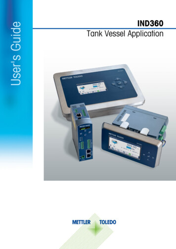
Introduction1.3.Display and Keypad1.3.1.IND360 DIN Rail-Mount VersionThe IND360 DIN rail-mount version includes a keypad (including four push buttons) and a1.04 inch OLED display. The keypad is used for Zero, Tare, Clear and ePrint operations andcannot be used to edit application parameters. Application parameters can be edited throughthe web interface.9111231067485Figure 1-1: IND360 DIN Rail-Mount Version HMI for Tank Vessel Application1-211.04“ OLEDDisplays inventory, weight value and other status information.2Keypad(Refer to Figure 1-1.)3Status indicatorsSYS indicates the operation status of the system; NW1 and NW2indicate the status of the network. (Refer to section 4.12.1.1,Diagnostic LEDs, in the IND360 Terminal and Transmitter TechnicalManual.)4Load cell interfaceVaries depending on the actual configuration. Connectivity to Analog(strain gauge), POWERCELL or Precision weighing devices. (Refer tosection A.3.6 Main Board Wiring Connections, in the IND360 Terminaland Transmitter Technical Manual for more information.)METTLER TOLEDO IND360 Tank and Vessel Application Software User's Guide30654704 00 04/2021
5Power input24VDC power input. (Refer to section A.3.5, Power Connection, in theIND360 Terminal and Transmitter Technical Manual, for moreinformation.)64-20mA analogoutputOptional 4-20mA analog output module. (Refer to section A.3.7.1,Analog Output and DIO Option, in the IND360 Terminal and TransmitterTechnical Manual, for more information.)7Discrete I/OAvailable with 3 inputs / 4 outputs or 5 inputs / 8 outputs. (Refer tosections 3.6.3.1, Discrete Input 1-5 and 3.6.3.2, Discrete Output, inthe IND360 Terminal and Transmitter Technical Manual, for detailedinformation on assignable functions to discrete inputs and outputs in atank vessel application.)8Automation BusConnectorVaries depending on the configuration.9Current material levelin weightShows the real-time material level in the weigh vessel as weight.10Current material levelin percentageShows the real-time material level in the weigh vessel in percentage.The percentage progress bar will not update if the tank vesselapplication has not started.11Graphic display ofcurrent material levelShows the real-time material level in the weigh vessel as a bar graph.Table 1-1: Keypad – IND360 DIN Rail-Mount VersionKey30654704 00 04/2021NameNormal OperationSetup MenuNumerical ValuesList SelectionTareTareUpIncrease valuePrevious item upZeroZeroBack / ExitSelect left digitExit parameterselectionClearClearDownDecrease valueNext item downePrint/SetupConfirm selectionePrint (short press)or enter parameter Select right digitEnter setup (long press) selection(No function)METTLER TOLEDO IND360 Tank and Vessel Application Software User's Guide1-3
Introduction1.3.2.IND360 Panel and Harsh VersionThe IND360 Panel and Harsh version offer a 4.3” TFT color display that supports parameterconfiguration using the tactile push buttons. The following figure shows the Human MachineInterface (HMI) of a Panel version.918762354Figure 1-2: IND360 Panel-Mount Version HMI for Tank Vessel Application1-41IP addressIP address of the IND360 terminal service interface (web interface)2Application statusTank/Vessel application status information (e.g. running, refilling).(Refer to Table 1-4: Application Status Icons.)3SoftkeysQuick access to device information, application statistics, configurationand SMART5 alarms. (Refer to Table 1-3: Softkeys.)4Lower limitLower threshold setting. Refer to section (4.2.2.4, Lower Limit, for moreinformation.)5Upper limitShows the higher threshold of the material level in the weigh vessel.(Refer to section 4.2.2.3, Upper Limit, for more information.)6KeypadKeys for navigation and configuration. (Refer to Table 1-2: Keypad –IND360 Panel-Mount Version.)7Current material levelin percentageShows the real-time material level in the weigh vessel in percentage.The percentage progress bar will not update if the Tank Vesselapplication is stopped.8Current material levelin weightShows the real-time material level in the weigh vessel as weight value.9Date & timeDisplays the current date and time.METTLER TOLEDO IND360 Tank and Vessel Application Software User's Guide30654704 00 04/2021
Table 1-2: Keypad – IND360 Panel-Mount VersionKeyNormalOperationNameSetup MenuNumericalValuesList SelectionTareTareUpIncrease valuePrevious item upZeroZeroBack / ExitSelect left digitExit parameterselectionClearClearDownDecreasevalueNext item downePrint/SetupePrint (shortpress)Enter setup (longpress)(No function)Select rightdigit(No function)EnterConfirm selectionEnter to parameterselection / setupAcceptAcceptTable 1-3: SoftkeysSoftkeyNameFunctionInformation RecallShows information of the terminal: model, serial number, softwareversion, approval, PLC type, node address, DIO type, etc.Application RecallInformationShows statistical data of the application. For Tank Vesselapplication, statistical data include Lower Limit Counts, UpperLimit Counts, and Refill Counts.ShortcutQuick access to frequently used parameters, which include TargetSource, Tank Capacity, Upper Limit, Lower Limit.Normal ConditionDevice/application is operating normally.Predictive AlarmRoutine test, calibration or preventative maintenancerecommended.Out ofSpecificationWrong operator action or device/application is operating out ofspecification.Imminent FailureWrong weight or equipment failure expected. The alarm can bereset but will reoccur every day. Please contact METTLER TOLEDOservice.FailureEquipment failure or incorrect weight. Clearing the alarm will notreset the condition. The device must be repaired to eliminate thealarm. Please contact METTLER TOLEDO service.Table 1-4: Application Status IconsIcon30654704 00 04/2021NameFunctionRunThe tank vessel application is in operation.StopThe tank vessel application is not in operation.METTLER TOLEDO IND360 Tank and Vessel Application Software User's Guide1-5
IntroductionIcon1.4.NameFunctionWeigh InThe tank vessel is refilling.Weigh OutThe tank vessel is discharging.Upper LimitThe material has met its high threshold weight and refilling isstopped.Lower LimitThe material has met its low threshold weight and refilling isstarted.Further InformationFor more information, please refer to the following documentation available online onwww.mt.com/ind-ind360-downloads: Tank/vessel application informationo 1-6IND360tank/vessel data sheetDevice information and drawingsoIND360base data sheetoIND360base manualPLC sample code for applications (refer to section 5.1, PLC Sample Code)METTLER TOLEDO IND360 Tank and Vessel Application Software User's Guide30654704 00 04/2021
2InstallationTo install and ground the terminal, refer to Appendix A, Installation, in the IND360 Terminal andTransmitter Technical Manual.Grounding performance of the equipment must be maintained in a goodcondition. Equipment grounding must be completed by a professional electrician.The METTLER TOLEDO Service Center offers supervision and consultation only.Complete the grounding of all equipment (power supply unit, weighing display, and scale,etc.), in reference to wiring diagrams of equipment and based on relevant national or localregulation requirements. In this process, it is essential to make sure that:All equipment enclosures are connected at the same earth potential through groundingterminals.No current flows circulating through the cable shield of any conductors such as the loadcell or scale.The neutral grounding point shall be as close to the weighing system as possible.30654704 00 04/2021METTLER TOLEDO IND360 Tank and Vessel Application Software User's Guide2-1
Installation2.1.WiringRefer to the wiring charts shown below to connect the terminal with a tank vessel system.METTLER TOLEDO recommends the addition of an externally-controlled safety mechanism forrefill.2.1.1.DIN Rail-Mount and Panel VersionFigure 2-1 shows a typical system layout with an IND360 DIN/Panel mount version and a tankvessel.Figure 2-1: IND360 Tank Vessel System Wiring ChartThe digital I/O block must be attached to a common ground or voltage source to be operated.A typical setup is shown in Figure 2-2, other combinations of sinking or sourcing input/outputare possible as well. Please refer to Appendix A, Installation, in the IND360 Terminal andTransmitter Techniccal Manual for additional information about the digital I/O.2-2METTLER TOLEDO IND360 Tank and Vessel Application Software User's Guide30654704 00 04/2021
Figure 2-2: Sinking input and Sourcing Output2.1.2.Harsh VersionFigure 2-3 shows a typical installation of the IND360 harsh environment version.Figure 2-3: Harsh Enclosure InstallationTable 2-1: Harsh Enclosure Opening Cable AssignmentsOpeningCable Gland Size, mm1Service Ethernet TCP/IP, M12 connector162Load cell or Weigh Module Connection163AC Power1644 20mA165DI/O16PLC options(PROFINET, PROFIBUS DP, EtherNet/IP orModbus RTU)166/730654704 00 04/2021UseMETTLER TOLEDO IND360 Tank and Vessel Application Software User's Guide2-3
2.2.Tank Vessel Application Setup ChecklistInstallationSite LocationIND360 Serial NumberLoad Cell Serial NumbersIP AddressesService port "LAN" (default: 192.168.0.8):Industrial Ethernet Port “X1.1” (optional):Industrial Ethernet Port “X1.2” (optional):Configuration Information1. IND360terminalPhysicalConnectionConnectivity of scale/load cells/junction box to IND360 terminal24 VDC power supply connected (DIN, Panel)Display connected (panel units), connector is marked “A, B, GND1, 12V”PLC network option connectedDiscrete input/output option connected4-20 mA analog output option connectedTechnical Manual ReferenceScale ParametersScale AdjustmentCommunication2. Application ApplicationConfiguration Parameter Setup3. HardwareSwitchesLocking FunctionSetup completed byScale type configuredSetup Scale Type3.5.1.1 TypeCapacity and increment configuredSetup Scale Capacity & Increment3.5.1.2 Capacity & IncrementCalibration settings (technology dependent)Setup Scale Calibration3.5.1.3 CalibrationZero adjustment: set gross weight of empty tank to zeroSetup Scale Calibration3.5.1.3.2 Zero AdjustSpan/Step (sensitivity) adjustment (technology dependent)Setup Scale Calibration3.5.1.3.3 Span AdjustDisable pushbutton taare and disable/configure pushbuttonzeroSetup Scale Zero & Tare3.5.1.4. Zero & TarePC communication and ePrint configured or deactivated(depending on use case)Setup Communication Service3.8.1 Service(Optional) Analog output and PLC interface configuredSetup Communication Analog output3.8.2 Analog OutputTank Vessel application activatedSetup Application PAC PAC Management3.6.4 PAC (Application Pack)ManagementTarget and alarm values definedSetup Application Tank Vessel4.2.2 and 4.2.3 of this manualDiscrete inputs assigned. Note: application can be started bydigital input or PLC commandSetup Application Tank Vessel4.2.5 of this manualDiscrete outputs assignedSetup Application Tank Vessel4.2.6 of this manuaSW1 (legal for trade) set if device used in metrologicalapproved setupA.4.1 Main PCB SwitchesSW2 (master reset) disabledA.4.1 Main PCB SwitchesName:Date:Signature:2-4METTLER TOLEDO IND360 Tank and Vessel Application Software User's Guide30654704 00 04/2021
3OperationThis chapter provides information about the tank vessel application implemented on an IND360terminal. It assumes that the user of this manual has reviewed and understood the operation ofthe standard IND360. Refer to the IND360 Terminal and Transmitter Technical Manual fordetails.Operation of the terminal depends on the enabled functionality and application setupparameters. The application configuration can be modified as necessary by users withappropriate access levels.3.1.Operating PrincipleThe tank vessel application provides tank inventory control by measuring the weight of the tankand its inventory. The fill level is indicated by the weight value of the content and percentage ofthe total tank capacity.The main functionality of the tank vessel application is defined by four configurable set points: Over Limit AlarmWhen this limit is exceeded, an alarm is triggered that notifies the userabout a dangerous overfilling condition, e.g. a blocked refill valve. Upper LimitWhen the current fill level reaches the upper limit, the refill signal isturned off. Lower LimitWhen the current fill level falls below the lower limit, the refill signal isturned on. Lower Limit Alarm Falling below this limit triggers an alarm notifying the user that thematerial level is critically low. This could be caused for example by abroken refill pump.The IND360 has the capability to indicate when the defined set points have been reached bothvia the automation interface and as a digital output signal (depending on output configuration).As a safety precaution, equip the refill control with logic that prohibits refilling under unsafeconditions.30654704 00 04/2021METTLER TOLEDO IND360 Tank and Vessel Application Software User's Guide3-1
OperationFigure 3-1: IND360 operating principle demonstrating the relevantset points and refill control.3.1.1.Example SequenceFigure 3-2 shows an IND360tank/vessel sequence. In the first cycle, the weight reaches theupper limit, the refill turns off and the weight drops again as the material is consumed.The second cycle demonstrates a case where the refill pump malfunctions and an alarm istriggered.Input and output signals are enabled once the run signal is switched on. Depending on thefilling level, the various output signals are set.3-2METTLER TOLEDO IND360 Tank and Vessel Application Software User's Guide30654704 00 04/2021
Figure 3-2: IND360tank/vessel Sequence Diagram.30654704 00 04/2021METTLER TOLEDO IND360 Tank and Vessel Application Software User's Guide3-3
Operation3.2.Typical Use CasesTypical use cases ranging from full PLC /DCS control to stand-alone operation are described inthe following four sections. Any combination thereof is possible as well, depending on theproject need.3.2.1.Automation Network with Direct Refill ControlThe IND360 controls the refill valve while providing visualization on the HMI. The PLC interfacehas cyclic and acyclic access to application status information and read/write of configuration.PROFINET and EtherNet/IP support redundant ring topology.Figure 3-3: IND360 Connected to Automation Bus3.2.2.Automation Network with Indirect Refill ControlFigure 3-4 shows an example in which the PLC controls the refill valve based on IND360 refillsignal and other control information. The IND360 provides tank filling level monitoring andvisualization on its HMI. The PLC interface has cyclic and acyclic access to application statusinformation and read/write of configuration. PROFINET and EtherNet/IP support redundant ringtopology.Figure 3-4: IND360 Connected to Automation Bus3-4METTLER TOLEDO IND360 Tank and Vessel Application Software User's Guide30654704 00 04/2021
3.2.3.Digital Input/Output Connectivity with PLC/DCSFigure 3-5 shows an example in which the IND360 controls the refill valve and providesvisualization on its HMI. PLC access to status information and control functionality using digitalI/O. Optional 4-20 mA weight output available configured via the web interface or display.Figure 3-5: IND360 Connected to PLC/DCS Using Digital Input/Output3.2.4.Stand-Alone Without PLC/DCSFigure 3-6 shows an example of an IND360 stand-alone setup without PLC connection, inwhich the IND360 controls the refill valve and provides visualization on its HMI. The applicationis started by a physical momentary contact switch attached to a digital input of IND360. The"Over Limit Alarm" signal must be connected to a safety switch acting as an emergency stop forthe refill function. Lights connected to physical outputs of IND360 show alarm status.Configuration is facilitated through the web interface or display.Figure 3-6: IND360 stand-alone operation3.3.Starting and Stopping the Tank Vessel ApplicationStarting or stopping the tank vessel application is controlled through a discrete input or viaPLC/DCS communication. The application cannot be started through the display, web interfaceor buttons.30654704 00 04/2021METTLER TOLEDO IND360 Tank and Vessel Application Software User's Guide3-5
3.4.User ManagementOperationIND360 supports three levels of user security that rely on appropriate username / passwordentry for access to Setup menu and Tank Vessel functions accessible from the home screen.When the application is running, the Setup menu can only be accessed as Operator andtherefore read-only mode. Refer to Section 2.2, User Security, in the IND360 Terminal andTransmitter Technical Manual for detailed information on user security.Table 3-1: Setup Menu Access LevelsSetup Menus3.5.AdministratorSupervisorOperatorScaleWrite & ReadReadReadApplicationWrite & ReadWrite & ReadReadTerminalWrite & ReadReadReadCommunicationWrite & ReadReadReadMaintenanceWrite & ReadWrite & ReadReadAlibi MemoryThe Alibi Memory is available when using the terminal in combination with the Tank Vesselapplication. Refer to Section 4.8, Alibi Log, in the IND360 Terminal and Transmitter TechnicalManual for detailed information on the Alibi Memory and instructions on how to receive the datarecords.3.6.ePrint FunctionFor Tank Vessel application, the ePrint template contains date and time, gross, tare, net andmaterial level in percentage (Figure 3-7). The ePrint template is not user configurable.For more information on how to use the ePrint function, please refer to Section 2.5.4, ePrint, inthe IND360 Terminal and Transmitter Technical Manual.Figure 3-7: ePrint Template of Tank Vessel Application3-6METTLER TOLEDO IND360 Tank and Vessel Application Software User's Guide30654704 00 04/2021
3.7.StatisticsStatistics stores statistical data for the Tank Vessel application: Lower Limit Counts: Incremented by one when the tank weight falls below the lower limit. Upper Limit Counts: Incremented by one when the tank weight exceeds the upper limit. Refill Counts: Incremented by one if refill signal is triggered.To view the stat
1-2 METTLER TOLEDO IND360 Tank and Vessel Application Software User's Guide 30654704 00 04/2021 Introduction 1.3. Display and Keypad 1.3.1. IND360 DIN Rail-Mount Version The IND360 DIN rail-mount version includes a keypad (including four push buttons) and a 1.04 inch OLED display.