Transcription
Avaya Solution & Interoperability Test LabApplication Notes for Configuring the AudioCodes MP-118Analog VoIP Gateway Utilizing Both the FXS/FXO Ports withAvaya SIP Enablement Services and Avaya CommunicationManager - Issue 1.0AbstractThese Application Notes describe the procedures for configuring the AudioCodes MP-118Analog VoIP Gateway with Avaya SIP Enablement Services and Avaya CommunicationManager.The AudioCodes MP-118 Analog VoIP Gateway (MP-118) serves as a gateway betweenlegacy analog endpoints/trunks at a branch location and a VoIP infrastructure at a mainlocation using the Session Initiation Protocol (SIP). The MP-118 has 4 FXS (analog endpoint)ports and 4 FXO (POTS trunk) ports. Earlier Application Notes focused on theinteroperability of the MP-118 with Avaya SIP Enablement Services and AvayaCommunication Manager in a test configuration utilizing only the FXS ports and isdocumented in [10]. These current Application Notes describe a test configuration that utilizesboth the FXS and FXO ports and are a super-set of the earlier Application Notes.Information in these Application Notes has been obtained through DeveloperConnectioncompliance testing and additional technical discussions. Testing was conducted via theDeveloperConnection Program at the Avaya Solution and Interoperability Test Lab.CTM; Reviewed:SPOC 6/28/2007Solution & Interoperability Test Lab Application Notes 2007 Avaya Inc. All Rights Reserved.1 of 64AC-MP118-FXO
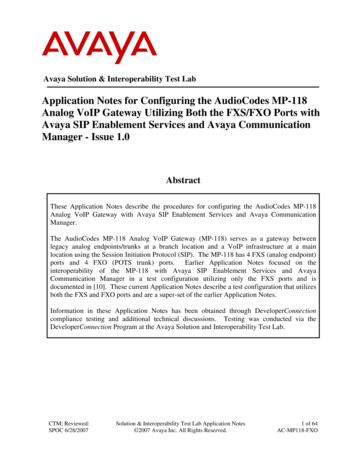
1. IntroductionThese Application Notes describe the procedures for configuring the AudioCodes MP-118 AnalogVoIP Gateway with Avaya SIP Enablement Services (SES) and Avaya Communication Manager.The AudioCodes MP-118 Analog VoIP Gateway (MP-118) serves as a gateway between legacyanalog endpoints/trunks at a branch location and a VoIP infrastructure at a main location using theSession Initiation Protocol (SIP). The MP-118 has 4 FXS (analog endpoint) ports and 4 FXO(POTS trunk) ports. The FXO ports are intended to be used for local inbound and outbound PSTNaccess for the users located at the branch. Users at the main location will obtain PSTN access fromthe main location. Thus, a call placed from each location dialed with the same destination digitstring will be routed differently based on where the call originates. This requires the use of theMultiple Locations feature on Avaya Communication Manager. The FXO ports are also used as afailover path if the data WAN is unavailable and SIP calls cannot be made. The data WAN beingunavailable and causing a failover can be due to three types of failures at the branch: a failure of theWAN link, a failure of the LAN providing access to the WAN or power loss of the MP-118. In thecase of power loss, the FXS ports are connected directly to the corresponding FXO ports (i.e., FXSport 1 is connected to FXO port 1, FXS port 2 is connected to FXO port 2, etc.).The FXO ports of the MP-118 will typically connect to POTS trunks from the PSTN which do notprovide any far-end disconnect indication. This may cause some undesirable behavior whenincoming trunk calls interact with some features like voicemail and conferencing. This is not alimitation of the MP-118 but a limitation of the functionality provided by the trunk. For a moredetailed discussion of this topic, see the test results in Section 6.2.The MP-118 registers with the Avaya SES as a SIP endpoint for each FXS or FXO port which isenabled. On the Avaya SES, the FXS ports are configured as users with media server extensions andthe FXO ports are configured as users without media server extensions. Thus, when calls are routedto Avaya Communication Manager, calls from the FXS ports appear as calls from extensions andcalls from the FXO ports appear as trunk calls.1.1. ConfigurationFigure 1 illustrates the configuration used in these Application Notes. In the sample configuration,two sites are connected via an IP network. The main site has an Avaya SES and an Avaya S8300Server running Avaya Communication Manager in an Avaya G700 Media Gateway. Endpointsinclude an Avaya 4600 Series IP Telephone (with SIP firmware), an Avaya 4600 Series IPTelephone (with H.323 firmware), an Avaya 6408D Digital Telephone, and a fax machine. AnISDN-PRI trunk connects the media gateway to the PSTN.The branch site has an AudioCodes MP-118 Analog VoIP Gateway with two analog telephones, anda fax machine. The branch site also has two Avaya 4600 Series IP Telephones (with SIP firmware).The MP-118 connects the branch site to the PSTN via an FXO (POTS) trunk. The other three FXOports were not connected. At the branch site, all SIP telephones and analog endpoints (MP-118 FXSports) are registered directly to Avaya SES and are administered as Outboard Proxy SIP (OPS)stations on Avaya Communication Manager. The PSTN trunk (MP-118 FXO port) is registered withCTM; Reviewed:SPOC 6/28/2007Solution & Interoperability Test Lab Application Notes 2007 Avaya Inc. All Rights Reserved.2 of 64AC-MP118-FXO
the SES but does not have an OPS station administered on Avaya Communication Manager. TheSIP telephones and the MP-118 use the IP network gateway as the default gateway. The MP-118only supports the operation of the analog endpoints and is not required for the SIP telephones. As aresult, if the data WAN is unavailable, the MP-118 allows the analog telephones to keep functioningbut the SIP telephones will not.The PSTN numbers assigned to the ISDN-PRI trunk at the main site are mapped to telephoneextensions at the main site. The PSTN number assigned to the POTS line at the branch site ismapped to an extension at the branch site.Figure 1: MP-118 Test ConfigurationCTM; Reviewed:SPOC 6/28/2007Solution & Interoperability Test Lab Application Notes 2007 Avaya Inc. All Rights Reserved.3 of 64AC-MP118-FXO
1.2. OperationAs mentioned previously, PSTN calls are routed based on the dialed digits as well as where the calloriginates. The Multiple Location feature and Automatic Route Selection (ARS) are used to providethis functionality. In addition, two SIP trunk groups are created between Avaya CommunicationManager and Avaya SES. The first trunk group is the initial SIP trunk group required of any SIPinstallation. It is associated with a SIP signaling group with the far-end domain set to the domain ofthe Avaya SES. The second trunk group is associated with a signaling group that uses the IP addressof the MP-118 as the far-end domain. This second domain information is passed to Avaya SES in theSIP signaling messages for calls using this second trunk group. This information allows the AvayaSES to route these calls to the MP-118.The call flow for an inbound and outbound call from the MP-118 is described below using thisconfiguration. It should be noted that even though the call originates and terminates on the MP-118,the call is sent to Avaya Communication Manager for processing. This allows AvayaCommunication Manager to apply access and routing criteria, as well as make available a wide rangeof PBX features to the call.Outbound call to the PSTN using the MP-118 FXO ports:1. An analog telephone connected to the MP-118 at the branch dials an ARS access code aPSTN number.2. The MP-118 initiates a SIP call to the Avaya SES with the SIP domain specified in theAvaya SES. This is the same SIP domain with which the endpoint registered (e.g.,business.com).3. The Avaya SES recognizes the call is from a registered user in its own domain which has amedia server extension assigned to it. Thus, Avaya SES routes the call automatically toAvaya Communication Manager.4. Based on the access code, Avaya Communication Manager uses ARS to route the call.Based on the location where the call originates, the Avaya Communication Manager willselect the proper ARS table unique to that location. This ARS table will point to a routepattern specific for that location.5. The route pattern will point to the SIP trunk group that is unique for that location which hasthe far-end domain set to the IP address of the MP-118.6. Based on this route pattern, Avaya Communication Manager routes the call back to theAvaya SES using this new trunk group. This has the effect of changing the SIP domain inthe SIP signaling messages to the IP address of the MP-118 instead of business.com.7. The Avaya SES receives the call and determines it is not for its own domain (business.com)so forwards it to the new domain (the MP-118 IP address).8. The MP-118 receives the call with the PSTN number and routes it to an available trunk.Inbound call from the PSTN using the MP-118 FXO ports:1. A PSTN caller dials a PSTN number that is associated with one of the POTS trunksconnected to the MP-118. The MP-118 maps this incoming call to an extension which canbe located at either site. This example assumes the mapped extension is one of the analogtelephones connected to the MP-118. The MP-118 will initiate a SIP call to the Avaya SESfor this extension.CTM; Reviewed:SPOC 6/28/2007Solution & Interoperability Test Lab Application Notes 2007 Avaya Inc. All Rights Reserved.4 of 64AC-MP118-FXO
2. The Avaya SES recognizes the call is for a registered user in its own domain which has amedia server extension assigned to it. Thus, Avaya SES routes the call automatically toAvaya Communication Manager.3. The Avaya Communication Manager receives the call and determines that the destinationextension is an OPS station associated with the SIP trunk connected to the Avaya SES. TheAvaya Communication Manager then routes the call back to the Avaya SES.4. The Avaya SES then routes the call to the registered IP address for that extension (the MP118).2. Equipment and Software ValidatedThe following equipment and software/firmware were used for the sample configuration provided:EquipmentAvaya S8300 Server with Avaya G700 MediaGatewayAvaya SIP Enablement Services (SES)Avaya 4602SW IP TelephoneAvaya 4620SW IP TelephonesAvaya 4625SW IP TelephoneAvaya 6408D Digital TelephoneAnalog TelephonesAnalog Fax MachinesWindows PCsAudioCodes MP-118 Analog VoIP GatewaySoftware/FirmwareAvaya Communication Manager 3.1.3(R013x.01.3.640.2)3.1.1SIP version 2.2.2H.323 version 2.7Windows XP Professional5.00A.011.0083. Configure Avaya Communication ManagerThis section describes the Avaya Communication Manager configuration. It is divided into threeparts. The first part is the initial SIP configuration required of any SIP installation. The second partdescribes the configuration needed for multiple location support and call routing based onorigination location. The third part includes the configuration of OPS stations.The following configuration of Avaya Communication Manager was performed using the SystemAccess Terminal (SAT). After the completion of the configuration in this section, perform a savetranslation command to make the changes permanent.CTM; Reviewed:SPOC 6/28/2007Solution & Interoperability Test Lab Application Notes 2007 Avaya Inc. All Rights Reserved.5 of 64AC-MP118-FXO
3.1. Initial SIP ConfigurationThis section describes the initial configuration required on the Avaya Communication Manager tosupport SIP.Step1.DescriptionUse the display system-parameters customer-options command to verify thatsufficient SIP trunk capacity exists. On Page 2, verify that the number of SIP trunkssupported by the system is sufficient for the number of SIP trunks needed. Each SIPcall between two SIP endpoints (whether internal or external) requires two SIP trunksfor the duration of the call. Thus, a call from a SIP telephone to another SIP telephonewill use two SIP trunks. A call between a non-SIP telephone and a SIP telephone willonly use one trunk. In this solution, each analog endpoint at the branch counts as a SIPtelephone.The license file installed on the system controls the maximum permitted. If a requiredfeature is not enabled or there is insufficient capacity, contact an authorized Avayasales representative to make the appropriate changes.display system-parameters customer-optionsOPTIONAL FEATURESPageIP PORT CAPACITIESMaximum Administered H.323 Trunks:Maximum Concurrently Registered IP Stations:Maximum Administered Remote Office Trunks:Maximum Concurrently Registered Remote Office Stations:Maximum Concurrently Registered IP eCons:Max Concur Registered Unauthenticated H.323 Stations:Maximum Video Capable H.323 Stations:Maximum Video Capable IP Softphones:Maximum Administered SIP Trunks:Maximum Number of DS1 Boards with Echo Cancellation:Maximum TN2501 VAL Boards:Maximum G250/G350/G700 VAL Sources:Maximum TN2602 Boards with 80 VoIP Channels:Maximum TN2602 Boards with 320 VoIP Channels:Maximum Number of Expanded Meet-me Conference Ports:10020000000100USED1000000002400500100010002 of10(NOTE: You must logoff & login to effect the permission changes.)CTM; Reviewed:SPOC 6/28/2007Solution & Interoperability Test Lab Application Notes 2007 Avaya Inc. All Rights Reserved.6 of 64AC-MP118-FXO
Step2.DescriptionIn order to support SIP the following features must be enabled. Use the displaysystem-parameters customer-options command to verify that the following fieldshave been set to y.Page 4: Enhanced EC500? yPage 4: ISDN-PRI? yPage 4: IP trunks? yIn addition, the compliance test used Automatic Route Selection (ARS) and theMultiple Locations feature to route PSTN bound calls (11 digit numbers) between thebranch and main sites. Thus, the following features must also be enabled.Page 3: ARS? yPage 5: Multiple Locations? yIf a required feature is not enabled, contact an authorized Avaya sales representative tomake the appropriate changes.3.Use the change node-names ip command to assign the node name and IP address forthe Avaya SES. In this case, SES and 10.75.5.6 are being used, respectively. Thenode name SES will be used throughout the other configuration forms of AvayaCommunication Manager. In this example, procr and 10.75.5.2 are the name and IPaddress assigned to the Avaya S8300 Server.change node-names ipNameSESdefaultmyaudixprocrCTM; Reviewed:SPOC 6/28/2007Page1001010IP Address.75 .5 .6.0 .0 .0.75 .5 .7.75 .5 .2IP NODE NAMESName1 of1IP Address.Solution & Interoperability Test Lab Application Notes 2007 Avaya Inc. All Rights Reserved.7 of 64AC-MP118-FXO
Step4.DescriptionUse the change ip-network-region n command, where n is the number of the regionto be changed, to define the connectivity settings for all VoIP resources and IPendpoints within the region. Select an IP network region that will contain the AvayaSES server. The association between this IP network region and the Avaya SES serverwill be done on the Signaling Group form as shown in Step 7. In the case of thecompliance test, the same IP network region that contains the Avaya S8300 Server andAvaya IP Telephones was selected to contain the Avaya SES server. By default, theAvaya S8300 Server and IP telephones are in IP network region 1.On the IP Network Region form:The Location field is set to 1. This associates this IP network region withlocation 1.The Authoritative Domain field is configured to match the domain nameconfigured on Avaya SES. In this configuration, the domain name isbusiness.com. This name will appear in the “From” header of SIP messagesoriginating from this IP region.Enter a descriptive name for the Name field.By default, IP-IP Direct Audio (shuffling) is enabled to allow audio traffic tobe sent directly between IP endpoints without using media resources in theAvaya G700 Media Gateway. This is true for both intra-region and inter-regionIP-IP Direct Audio. Shuffling can be further restricted at the trunk level on theSignaling Group form.The Codec Set is set to the number of the IP codec set to be used for callswithin this IP network region. If different IP network regions are used for theAvaya S8300 Server and the Avaya SES server, then Page 3 of each IPNetwork Region form must be used to specify the codec set for inter-regioncommunications.The Audio PHB Value is 46, which translate to a DiffServ header value of0xb8.The default values can be used for all other fields.change ip-network-region 1Page1 of19IP NETWORK REGIONRegion: 1Location: 1Authoritative Domain: business.comName: defaultMEDIA PARAMETERSIntra-region IP-IP Direct Audio: yesCodec Set: 1Inter-region IP-IP Direct Audio: yesUDP Port Min: 2048IP Audio Hairpinning? nUDP Port Max: 3327DIFFSERV/TOS PARAMETERSRTCP Reporting Enabled? yCall Control PHB Value: 46RTCP MONITOR SERVER PARAMETERSAudio PHB Value: 46Use Default Server Parameters? yVideo PHB Value: 26802.1P/Q PARAMETERSCall Control 802.1p Priority: 6Audio 802.1p Priority: 6Video 802.1p Priority: 5AUDIO RESOURCE RESERVATION PARAMETERSH.323 IP ENDPOINTSRSVP Enabled? nH.323 Link Bounce Recovery? yIdle Traffic Interval (sec): 20Keep-Alive Interval (sec): 5Keep-Alive Count: 5CTM; Reviewed:SPOC 6/28/2007Solution & Interoperability Test Lab Application Notes 2007 Avaya Inc. All Rights Reserved.8 of 64AC-MP118-FXO
Step5.DescriptionUse the change ip-codec-set n command, where n is the codec set value specified inStep 4, to enter the supported audio codecs for calls routed to Avaya SES. Multiplecodecs can be listed in priority order to allow the codec to be negotiated during callestablishment. The list should include the codecs the enterprise wishes to supportwithin the normal trade-off of bandwidth versus voice quality. The example belowshows the values used in the compliance test.change ip-codec-set 1Page1 of2IP Codec SetCodec Set: 1AudioCodec1: G.711MU2: G.729AB3:6.SilenceSuppressionnnFramesPer Pkt22PacketSize(ms)2020On Page 2, the FAX Mode field must be set to t.38-standard to support the faxmachines. The Modem field should be set to off. The screen below shows the settingused for the fax testing.change ip-codec-set 1Page2 of2IP Codec SetAllow Direct-IP Multimedia? nFAXModemTDD/TTYClear-channelCTM; Reviewed:SPOC tion & Interoperability Test Lab Application Notes 2007 Avaya Inc. All Rights Reserved.9 of 64AC-MP118-FXO
Step7.DescriptionUse the add signaling-group n command, where n is the number of an unusedsignaling group, to create the SIP signaling group as follows:Set the Group Type field to sip.The Transport Method field will default to tls (Transport Layer Security).TLS is the only link protocol that is supported for communication betweenAvaya SES and Avaya Communication Manager.Specify the Avaya S8300 Server (node name procr) and the Avaya SES Server(node name SES) as the two ends of the signaling group in the Near-end NodeName and the Far-end Node Name fields, respectively. These field values aretaken from the IP Node Names form shown in Step 3. For alternativeconfigurations that use a C-LAN board, the near (local) end of the SIP signalinggroup will be the C-LAN board instead of the Avaya S8300 Server.Ensure that the recommended TLS port value of 5061 is configured in theNear-end Listen Port and the Far-end Listen Port fields.In the Far-end Network Region field, enter the IP network region valueassigned in the IP Network Region form in Step 4. This defines which IPnetwork region contains the Avaya SES server. If the Far-end NetworkRegion field is different from the near-end network region, the preferred codecwill be selected from the IP codec set assigned for the inter-region connectivityfor the pair of network regions.Enter the domain name of Avaya SES in the Far-end Domain field. In thisconfiguration, the domain name is business.com. This domain is specified inthe Uniform Resource Identifier (URI) of the SIP “To” header in the INVITEmessage.The Direct IP-IP Audio Connections field is set to y.The DTMF over IP field must be set to the default value of rtp-payload for aSIP trunk. This value enables Avaya Communication Manager to send DTMFtransmissions using RFC 2833.The default values for the other fields may be used.add signaling-group 1Page1 of1SIGNALING GROUPGroup Number: 1Group Type: sipTransport Method: tlsNear-end Node Name: procrNear-end Listen Port: 5061Far-end Node Name: SESFar-end Listen Port: 5061Far-end Network Region: 1Far-end Domain: business.comBypass If IP Threshold Exceeded? nDTMF over IP: rtp-payloadDirect IP-IP Audio Connections? yIP Audio Hairpinning? nSession Establishment Timer(min): 120CTM; Reviewed:SPOC 6/28/2007Solution & Interoperability Test Lab Application Notes 2007 Avaya Inc. All Rights Reserved.10 of 64AC-MP118-FXO
Step8.DescriptionAdd a SIP trunk group by using the add trunk-group n command, where n is thenumber of an unused trunk group. For the compliance test, trunk group number 1 waschosen.On Page 1, set the fields to the following values:Set the Group Type field to sip.Choose a descriptive Group Name.Specify an available trunk access code (TAC) that is consistent with theexisting dial plan.Set the Service Type field to tie.Specify the signaling group associated with this trunk group in the SignalingGroup field as previously specified in Step 7.Specify the Number of Members supported by this SIP trunk group. Asmentioned earlier, each SIP call between two SIP endpoints (whether internalor external) requires two SIP trunks for the duration of the call. Thus, a callfrom a SIP telephone to another SIP telephone will use two SIP trunks. A callbetween a non-SIP telephone and a SIP telephone will only use one trunk.The default values may be retained for the other fields.add trunk-group 1Page1 of21TRUNK GROUPGroup Number:Group Name:Direction:Dial Access?Queue Length:Service Type:1SES Trk Grptwo-wayn0tieGroup Type: sipCOR: 1Outgoing Display? nTN: 1CDR Reports: yTAC: 101Night Service:Auth Code? nSignaling Group: 1Number of Members: 249.On Page 3:Verify the Numbering Format field is set to public. This field specifies theformat of the calling party number sent to the far-end.The default values may be retained for the other fields.add trunk-group 1TRUNK FEATURESACA Assignment? nPage3 of21Measured: noneMaintenance Tests? yNumbering Format: publicPrepend ' ' to Calling Number? nReplace Unavailable Numbers? nCTM; Reviewed:SPOC 6/28/2007Solution & Interoperability Test Lab Application Notes 2007 Avaya Inc. All Rights Reserved.11 of 64AC-MP118-FXO
Step10.DescriptionUse the change public-unknown-numbering 0 command to define the full callingparty number to be sent to the far-end. Add an entry for the trunk group defined inStep 8. In the example shown below, all calls originating from a 5-digit extensionbeginning with 3 and routed across trunk group 1 will be sent as a 5 digit callingnumber. This calling party number will be sent to the far-end in the SIP “From”header.change public-unknown-numbering 0NUMBERING - PUBLIC/UNKNOWN FORMATTotalExt ExtTrkCPNCPN Ext ExtTrkLen CodeGrp(s)PrefixLen Len CodeGrp(s)5 35 311.199Page1 of2TotalCPNLenCPNPrefix55Create a route pattern that will use the SIP trunk that connects to Avaya SES. Thisroute pattern will be used as a default route for SIP calls in Step 12. Some transferscenarios using alphanumeric handles (i.e., user names) instead of extensions require adefault route pattern. These call scenarios were not tested as part of the compliancetest, however, the creation of this default route pattern is included here forcompleteness.To create a route pattern, use the change route-pattern n command, where n is thenumber of an unused route pattern. Enter a descriptive name for the Pattern Namefield. Set the Grp No field to the trunk group number created for the SIP trunk. Setthe Facility Restriction Level (FRL) field to a level that allows access to this trunk forall users that require it. The value of 0 is the least restrictive level. The default valuesmay be retained for all other fields.change route-pattern 1Pattern Number: 3Pattern Name: SIPSCCAN? nSecure SIP? nGrp FRL NPA Pfx Hop Toll No. InsertedNoMrk Lmt List Del DigitsDgts1: 102:3:4:5:6:1:2:3:4:5:6:BCC VALUE TSC CA-TSC0 1 2 3 4 WRequestITC BCIE Service/Feature PARMyyyyyyrestrestrestrestrestrestCTM; Reviewed:SPOC 6/28/2007yyyyyyyyyyyyyyyyyyyyyyyynnnnnnnnnnnnPage1 . Numbering LARDgts FormatSubaddressnonenonenonenonenonenoneSolution & Interoperability Test Lab Application Notes 2007 Avaya Inc. All Rights Reserved.12 of 64AC-MP118-FXO
Step12.DescriptionUse the change locations command to assign the default SIP route pattern to thelocation. This location uses the default name of Main and is shown in the examplebelow. Enter the route pattern number from the previous step in the Proxy Sel. Rte.Pat. field. The default values may be retained for all other fields.change locationsPage1 of4LOCATIONSARS Prefix 1 Required For 10-Digit NANP Calls? yLoc. NameNo.1:Main2:3:13.Timezone RuleOffset 00:000::NPAARSFACAttdFACPrefixProxy Sel.Rte. Pat.1ARS is used to route calls to the PSTN. If the Multiple Location feature is enabled,ARS supports multiple ARS Digit Analysis Tables. A separate table is supported foreach location as well as a general table which is used if a matching entry cannot befound in the location specific table. In the compliance test, the location 1 table wasblank so that location 1 (the main site) would use the general table for ARS routing.PSTN numbers that begin with 1732 were used for testing.Use the change ars analysis n command to add an entry in the general table for thedialed string beginning with n. The general table is shown below as indicated by theLocation field being set to all. In the example shown, PSTN numbers that begin with1732 and 11 digits long use route pattern 2. Route pattern 2 routes calls to the ISDNPRI trunk between the main site and the PSTN shown in Figure 1. The configurationof the PRI trunk is beyond the scope of these Application Notes.change ars analysis 1732PageARS DIGIT ANALYSIS TABLELocation: allDialedString1732174175176177CTM; Reviewed:SPOC 6/28/2007TotalMin nyCallTypefnpafnpafnpafnpafnpa1 ofPercent Full:NodeNum23ANIReqdnnnnnSolution & Interoperability Test Lab Application Notes 2007 Avaya Inc. All Rights Reserved.13 of 64AC-MP118-FXO
Step14.DescriptionTo map a PSTN number to a station at the main or branch office, use the change inccall-handling-trmt trunk-group n command, where n is the trunk group numberconnected to the PSTN from the Avaya G700 Media Gateway. The compliance testused trunk group 2 to connect to the PSTN. This trunk group configuration is notshown in these Application Notes. The example below shows two incoming 11-digitnumbers being deleted and replaced with the extension number of the desired station.change inc-call-handling-trmt trunk-group 2INCOMING CALL HANDLING TREATMENTService/CalledCalledDel InsertFeatureLenNumbertie11 173255512401130104tie11 173255512411130105CTM; Reviewed:SPOC 6/28/2007Solution & Interoperability Test Lab Application Notes 2007 Avaya Inc. All Rights Reserved.Page1 of314 of 64AC-MP118-FXO
3.2. Multiple Location SupportThis section describes the configuration necessary to define the physical branch location as a secondlocation within Avaya Communication Manager with separate routing tables from the main site.These steps are not necessary if routing based on the call origination location is not required. In thecase where it is not necessary to route calls based on the call origination location, the two physicallocations could still be represented by a single logical location within Avaya CommunicationManager.Step1.DescriptionUse the change locations command to define a second location and assign the defaultSIP route pattern to the location. In the compliance test, the second location is namedBranch. Enter the same default route pattern number that is used for location 1 namedMain in the Proxy Sel. Rte. Pat. field. The default values may be retained for all otherfields.change locationsPage1 of4LOCATIONSARS Prefix 1 Required For 10-Digit NANP Calls? yLoc. NameNo.1:Main2:Branch3:2.Timezone RuleOffset 00:000 00:000:NPAARSFACAttdFACPrefixProxy Sel.Rte. Pat.11Use the change ip-network-region 2 command to define an IP network region forlocation 2 which represents the branch site. Use the same values shown in Section 3.1,Step 4 for IP network region 1 with the following exceptions. Set the Location field to2 and the Name field to a descriptive name for the branch site.change ip-network-region 2Page1 of19IP NETWORK REGIONRegion: 2Location: 2Authoritative Domain: business.comName: BranchMEDIA PARAMETERSIntra-region IP-IP Direct Audio: yesCodec Set: 1Inter-region IP-IP Direct Audio: yesUDP Port Min: 2048IP Audio Hairpinning? nUDP Port Max: 3327DIFFSERV/TOS PARAMETERSRTCP Reporting Enabled? yCall Control PHB Value: 46RTCP MONITOR SERVER PARAMETERSAudio PHB Value: 46Use Default Server Parameters? yVideo PHB Value: 26802.1P/Q PARAMETERSCall Control 802.1p Priority: 6Audio 802.1p Priority: 6Video 802.1p Priority: 5AUDIO RESOURCE RESERVATION PARAMETERSH.323 IP ENDPOINTSRSVP Enabled? nH.323 Link Bounce Recovery? yIdle Traffic Interval (sec): 20Keep-Alive Interval (sec): 5Keep-Alive Count: 5CTM; Reviewed:SPOC 6/28/2007Solution & Interoperability Test Lab Application Notes 2007 Avaya Inc. All Rights Reserved.15 of 64AC-MP118-FXO
Step3.DescriptionOn Page 3, define the codec set to be used when placing calls between IP networkregion 2 and IP network region 1 (shown in Section 3.1, Step 6). Locate the entry inthe table for src rgn 2 and dst rgn 1 and enter the following values.codec set: 1direct WAN: yTotal WAN-BW-limits: :NoLimitVideo WAN-BW-limits: :NoLimitUse default values for all other fields.On Page 3, define the codec set to be used when placing calls between IP networkregion 2 and IP network region 1. Use the same values as shown in Section 3.1, Step5.change ip-network-region 2Page3 of19Inter Network Region Connection Managementsrcrgn2222dst codec directTotalrgn setWAN imitDynCAC IGARnIntervening-regions4.Repeat the previous step for IP network region 1 shown in Section 3.1, Step 4. Locatethe entry in the table for src rgn 1 and dst rgn 2 and enter the same values as sh
Communication Manager to apply access and routing criteria, as well as make available a wide range of PBX features to the call. Outbound call to the PSTN using the MP-118 FXO ports: 1. An analog telephone connected to the MP-118 at the branch dials an ARS access code a PSTN number. 2.