Transcription
Dipl.-Ing. Arnd Meyer,ErlangenWheel sets orindependently rotatingwheels – from theoryto practicesiemens.com/mobility1
AbstractBogies with independently rotating wheels (IRW) seem to be onlya compromise because there is a lack of space for an axle. This paper explains the theory of track guiding by IRW and shows that IRW have someadvantages over conventional wheelsets when these are used in tramwaysystems with their tight curves. These considerations are then backedup by field data, demonstrating that trams with IRW offer excellent ride quality and low levels of wheel/rail wear – if the particu larities of thisprinciple are considered.1. Introduction“Axle or no axle, that is the question!” Thismisquotation of Shakespeare aptly sums upwhat has to be considered for the guidanceconcept of tramway running gears. Whereasmain-line railways almost exclusively makeuse of bogies with stiff wheelsets, there isdisagreement in the tram sector. As tempting as the possibilities of independently rotating wheels (IRW) are for low floors allthe way through the passenger compartment, there is equally great skepticismabout giving up the wheel set axle principlethat has been tried and tested in almost200 years of service.This paper should help, on a factual basis,to decide which guidance principle representsthe best compromise for actual conditionsof use. Whereas the surprisingly complextheory of the movement of independentlyrotating wheels was highlighted in [1] and[2], this paper establishes the relationshipwith the overall vehicle and presents resultsgained from practice. As good as our theoretical understanding of track guidance maybe, only practice can show whether thecompromise between the different requirements has succeeded. Using the exampleof the Siemens Avenio low-floor tram forMunich, this paper shows how a successfulimplementation with a high quality ridecomfort and low wear can appear in practice.22. Requirements for running gearsIf different concepts are to be assessed,the requirements must first be clarified.The focus here shall be on requirementsthat differentiate between concepts. For example, reliable guidance is a fundamentalprerequisite and features in every approvedvehicle. Wear behavior and ride comfort,however, are strongly influenced by thetrack guidance concept.2.1 Low wearThe re-profiling and replacement of tiresdue to wear is one of the most expensive individual items in vehicle maintenance.It is clear that the guidance principle hasa considerable influence on this. Particularattention will be paid to this subject in thefollowing.2.2 High level of ride comfortInfluenced by the design criteria of themain-line railways, vibrations in the z-direction (vehicle vertical axis) are key to the assessment of ride comfort. In the case oftrams, however, due to the frequency ofchanges in the track curvature, the comfortin the y-direction (vehicle transverse axis) isat least as important. It is essential here todemonstrate how and to what extent this isinfluenced by the guidance concept.
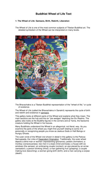
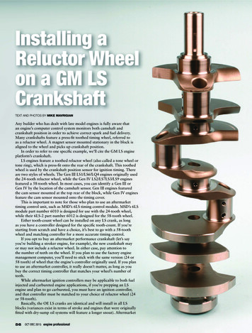
3. Assessment of the guidanceof wheelsets and IRWs3.1 What is guidance?Guidance is the specification of the directionof movement of vehicles by the guideway.This requires that the bogies must auto matically be able to free themselves from incorrect orientations. Possible incorrect orientations are a lateral offset, a misalignment within the track or the combinationof the two (Fig. 1). The wheel-rail contactforces necessary for the centering can begeometrical profile forces or frictional forces.Frictional forces occur in the case of a rollingwheel when there is a relative movement –a slip – between the wheel and rail contactsurfaces. This may be in the longitudinal direction, as in the case of a driven or brakedwheel (Fig. 2, right) or in the lateral direction.A slip in the lateral direction occurs whenthe wheel, as shown in Fig. 2, left, is notaligned parallel to the rail. The overallmovement in the contact point is not totallyaligned with the rolling direction, andthus, the lateral component results in slip.Longitudinal and lateral friction forces canbe used for guidance, but are associatedwith wear, as slip and force both point inthe same direction and thus perform work –wear work.Geometrical profile forces are understoodto mean the normal force at the rail-wheelcontact point. If this force has a componentin the lateral direction (designated Sy inFig. 3), this may be used for guidance.As the main direction of wheel movementfollows the rail in the longitudinal directionof the track, Sy is perpendicular to this andthus does not perform any work. Guidancewith geometrical profile forces is thereforepractically free from wear.Laterally displaced bogieMisaligned bogieFig. 1: Possible incorrect positions of the running gear on the trackLateral wheel slipLongitudinal wheel slipFig. 2: Friction forces in transverse and longitudinal direction at the wheel/rail contact pointv: Running speedFx, Fy: Friction forces3.2 Running on straight track3.2.1 The wheel setThe guidance mechanisms of the wheel seton straight tracks are generally well known.If a wheelset is offset laterally, the wheel radii at the contact point of the wheels aredifferent. Due to the rigid rotational speedcoupling, one wheel becomes the drivingwheel and the other becomes the brakingwheel. This leads to a “steering movement”that guides the wheel set back to the trackcentre. The movement continues beyondthe centerline, until a situation arises thatis the mirror image of the starting position –and the process begins again (see Fig. 4).Figure 3: Breakdown of the geometrical profile forces at the wheel/rail contact pointQ: Wheel loadN: Normal force in the contact surfaceSy, Sz: geometrical profile forces in y and z directionγ: Contact surface inclination3
This repeated movement is called “sinusoidalor hunting motion” [3] and was describedfor the first time by Johannes Klingel in1883.Fig. 4: Hunting motion of the wheel setFx: Longitudinal friction forceIt is clear that this mechanism alone is sufficient to correct not only a lateral offset, butalso a misalignment within the rail. Thisfunctions just as well for a single wheel setas for two wheel sets combined to forma bogie.“Hunting motion” on straight tracks resultsin a largely evenly distributed abrasion ofthe wheel treads, whereby however onlylongitudinal friction forces are “used”, whichare prone to cause wear. The axle movementof the wheel set is transferred to the entirevehicle and thus affects the ride comfort.In addition, the stability of the hunting oscillation depends on the running speed. Foreach design there is a “critical speed” abovewhich the running becomes unstable andthe vehicle inevitably derails. This speedcan be influenced by a variety of design parameters, so that it does not pose a hazardin practice. The effect, however, forces compromises to be made in the design to thedisadvantage of ride quality and wheel-railwear.Fig. 5: Balance of forces on laterally offset pair of single wheelsN: Normal force in the contact surfaceSy: Geometrical profile forces in y directionγ: Contact surface inclinationdelta tan(gamma): Centering factorFig. 6: Release of IRW from lateral offset and misalignment due to geometrical profile forcesSy: Geometrical profile forces in y direction43.2.2 The independently rotating wheelThe guidance of IRWs is based on completelydifferent modes of action in which thewheel profile geometry plays a decisive role.Whereas a conical profile is sufficient for thewheel set hunting oscillation, the geometryin the case of independently rotating wheelsmust exhibit an increasing gradient fromthe wheel tread to the wheel flange. Fig 5shows that a lateral offset of the pair ofwheels results in unequally large Sy forceson the left and right wheels, so that a centering effect is created. The magnitude of thecentering force is a function of the lateraloffset. The diagram represents the centeringfactor “delta tan(gamma)”. This, multipliedby the mean wheel load, produces the centering force acting on the pair of wheels.On railways using IRWs the centering forceis responsible for the release not only froma lateral offset, but also from a misalignmentof the bogie (see Fig. 6). The geometricalprofile forces Sy act vertically to the runningdirection and are therefore practically freefrom wear.
The hollow profile geometry necessary forthe guidance of IRWs offers further advantages over conical profiles. As far back asthe early 1970s, the UIC-ORE StandardizedProfile S1002 [4] was developed for mainline railways. The aim of this developmentwas to guarantee a profile form that wouldremain as constant as possible over the service life, despite the unavoidable wear.Although nobody thought of IRWs duringthe development, the S1002 would havebeen quite suitable for achieving reasonableguidance with IRWs.Due to the lack of a rigid rotational speedcoupling between the IRWs, there is in practice no hunting oscillation and thus noresulting “critical speed” or negative impacton ride comfort. Interestingly, Prof. Dellmannand Dr. Abdelfattah demonstrate in [1] and[2] that a pair of independently rotatingwheels also performs hunting oscillationsimilar to that of a wheel set. The examinations relate however to an individual pairof independently rotating wheels without acarbody supported on them. If one adds tothe model a connection to the running gearand the mass and mass inertia of a car body,the effect is lost – as is to be observed inpractice.Fig. 7: Wheel radius difference between left and right wheel with lateral offset in trackγ: Lateral offset in trackDelta R: Difference in radius of the wheelsWheel diameter 600 mmMeter gaugeIt should be remembered that the centeringeffect exclusively from the geometrical profile forces is less than that of a wheelset. When designing the running gear, therefore, great importance must be attachedto the exact parallelism of the “axles” as wellas of the wheels. If this is s uccessful, the unwanted single-sided wheel flange contactof IRWs does not arise either.3.2.3 The comparisonWheel sets represent a functioning guidanceconcept that has been known for almost200 years which, however, on the basis ofthe hunting oscillation, induces unwantedvibrations into the vehicle. IRWs are not subject to this effect and thus allow very calmrunning with low wear on straight tracks.A low level of wear, however, presupposesparticular attention being paid to axle andwheel parallelism and a suitable wheel profile in the design of the IRW running gear.Fig. 8: Wheel radius difference that is necessary for rolling free from longitudinal slip,in relation to curve radius.dr: Difference in wheel radiusR: Curve radius5
Adhesion coefficientSlipFig. 9: Friction force slip function for the longitudinal direction accordingto a measurement determined by Deutsche Bahn (Source [5])3.3 Running in a curve3.3.1 The wheel setDespite the rigid rotational speed couplingbetween the rotation of inner and outercurve wheels, wheel sets can roll withoutslip on large radii curves. This is possible because the lateral offset towards the outerrail of the curve causes a wheel radius difference Delta R to build up (see Fig. 7),which means that the circumferential speedat the contact point for the outer wheel isgreater than that of the inner wheel. Thisproperty – the automatic steering in curves– makes the wheel set the (almost) undisputed guidance element for main-line railways. One way in which tram networks differfrom main-line railways, however, are intheir significantly tighter curve radii. Radiiof 20 m are frequently encountered andeven 15 m radii are to be found. The mechanism of the wheel sets, however, no longerfunctions with these small curve radii. Fig. 8specifies for a typical tram system whichwheel radius difference is necessary in orderto enable the wheels to roll without longitudinal slip. By adopting a reasonable wheel/rail pairing the maximum possible difference is 4 mm. At this point, contact occursbetween the wheel flange and the rail.These 4 mm, however, only permit slip-freerunning on a 80 m radius curve. Even the“popular” 25 m radius curve requires a14 mm difference. It is clear that longitu dinal slip is the rule rather than exceptionwhen negotiating tramway curves withwheels sets – longitudinal slip that i nevitablyleads to wear. This can be quantified bymeans of an example:Running on a curve with R 30 m under theconditions shown in Fig. 8 geometricallyproduces a longitudinal slip of 1%. Accordingto Fig. 9 on a dry rail, this results in a friction force coefficient of 0.3. With a wheelload of 40 kN (VDV 2/3 loading) a frictionalforce of 12 kN is acting on every wheel!Torque per motor in NmTorque without wheel radius differenceTorque 600 mmTorque 596 mmMotor speedFig. 10: Torque-speed characteristic of the Avenio motors when controlled via a common traction converter with or without wheel radius differences at the contact pointsdM: Differential torque between right and left motor6
3.3.2 The independently rotating wheelThe mechanism that allows IRWs to steerautomatically in curves is the same that releases them from misalignment on astraight track (see Fig. 6). Whether the running gear is misaligned relative to the track,or the track turns under the running gear(entry to curve), is unimportant. IRWs haveno rigid mechanical rotational speed couplingand are therefore in principle not affectedby the longitudinal slip that occurs in tightcurves – provided they are not connected bymeans of an “electrical shaft”. The right andleft wheels on IRWs are frequently controlledby the same traction converter and thereforereceive a stator phase sequence with anidentical rotational speed. If the rotationalspeed of the wheel were linked rigidly tothe phase sequence, this would producethe same conditions as in the mechanicalcoupling. With the asynchronous machinesnormally used, this rigid coupling does notexist, but instead it behaves more like a rotational damper between the left andright wheel. The effect of this “rotationaldamper” should now be quantified.In the following IRWs with longitudinaldrive coupling from Siemens are considered.Longitudinally coupled IRWs were developed for the Combino fleet of vehicles andadopted virtually unchanged for the AvenioM platform (Ulm, Germany). The runninggear of the Avenio platform (Munich, TheHague, Qatar) has also adopted this triedand tested system, the connection of therunning gear to the carbody being adaptedto the different requirements of a single- articulated vehicle as opposed to thoseof a multi-articulated vehicle. For the sakeof simplicity, the running gear of all threefamilies of vehicles are referred to below as“Avenio running gear”. If the specific vehicletype is relevant to the consideration, this isreferred to in the text.The tram is run on a curve with R 30 mwith the lateral acceleration specifiedin the BOStrab alignment guidelines ofaq 0.65 m/s² and thus with a runningspeed of 16 km/h. As shown in Fig. 8, awheel radius difference of drnec 10 mm isnecessary in order to pass through the curvewith the same rotational speeds at the leftand right wheels. For the wheel/rail pairingunder consideration here, however, onlya maximum difference of drposs 4 mm ispossible. Six millimeters are therefore missing (drmiss 6 mm), which leads to a loadtorque between the wheels. Fig. 10 showsthe magnitude of this torque for a radiusdifference of 2 mm at the maximum motorFig. 11: Operating principle of the longitudinal drive when bogie is misaligned in the trackSy: Geometrical profile forces in y directionFx: Longitudinal geometrical profile forcesMotor bogieFelongTrailer bogieFdrivFelongMotor bogieFelongFelongFdrivFig. 12: Principle of “vehicle stretching” to support the centering of the trailer bogie, usingthe example of the Avenio MFdriv: Average driving force of the motor bogiesFelong: Superimposed stretching forcetorque. Taking into account the gear ratio,the wheel diameter and the fact that twowheels are driven by one motor (longitudinaldrive of the Avenio), this gives a longitudinalforce at the wheel/rail contact point ofFx,max,2 1.8 kN per wheel. In our example,the effective radius difference is 6 mm,so that the value for 2 mm is extrapolatedto three times the value on a simplified linear basis. At the maximum motor torquethis would produce a longitudinal force ofFx,max,6 5.4 kN per wheel. Level running onthe curve with R 30 m, however, does notdemand the maximum motor torque, butonly about 20% of it. The majority of thetractive resistance is generated by the curveresistance. This arises mainly from the lateralslip of the wheels due to the crab positionof the running gear in tight curves. This isa phenomenon that affects all running gearin which the wheels cannot position themselves completely radially in curves – regardless of whether they are wheel setsor IRWs. On obtaining 20% of the maximumtorque, the longitudinal force is reduced –again interpolated on a simplified linear basis – likewise to one fifth and thus toFx 1.1 kN. Running in tight curves withoutlongitudinal slip is not generally possible,even with driven or braked IRWs.7
FrequencyFig. 13: Measuring points (red dots) for the ride comfort of the Avenio Munichemptyuncomfortableaveragecomfortablevery comfortableladen4. Measures for centeringthe running gearIRWs exhibit a smaller centering effect thanwheel sets. This fact must be considered inthe design of the vehicle and running gear,if the above-mentioned advantages in termsof wear behavior are not to be negated.Three different measures are described below which are used on Siemens tram vehicles.Average ride comfortempty and ladenemptyFig. 15: Frequency distribution of the NMV characteristics according to EN 12299in the ride comfort measurements of the Avenio Munich8uncomfortableaveragecomfortableladenvery comfortableFrequencyFig. 14: Frequency distribution of the CCy characteristics according to EN 12299in the ride comfort measurements of the Avenio MunichAverage ride comfort emptyAverage ride comfort laden3.3.3 The comparisonThe wheel set principle fails in the case oftight curve radii that are typical of tram networks. The possible wheel radius differenceis insufficient by a long way to prevent rolling of the wheels without longitudinal slip.Even taking into consideration an “electricshaft”, a significantly reduced longitudinalslip occurs in the case of IRWs. In a curvewith radius R 30 m the longitudinal slipforce for the wheel set is 12 kN and therefore greater by a factor of 10 than for theIRWs at 1.1 kN!4.1 Omission of articulation dampersArticulation dampers, which are used to attenuate the yaw movement between twocar sections, are frequently encountered ontramway vehicles. These dampers, however,also slow down the tangential positioningof the carbodies after entering or leaving acurve and thus also – especially in the caseof multi-articulated vehicles – the tangentialpositioning of the running gear. The unavoidable dry friction component of the damperscan even result in a persistently incorrectorientation and thus a rail one-sided flangecontact by the running gear. Especially inthe case of vehicles with IRWs, therefore, articulation dampers are to be avoided. Theabsence of “hunting motion” with this running gear – assuming there is a well attunedrunning gear connection – makes this easilypossible. Siemens trams show no tendencytoward yaw vibrations, even without articulation dampers.
OperatorVehicle typeNumberof vehiclesMD/BDGauge [mm]Tire servicelife [km]Reprofilinginterval [km]BernmobilCombino36MD1000MB: 280,000TB: 260,000MB: 40,000TB: 40,000MPKPoznanCombino14MD1435MB: 217,135TB: 209,630MB: 25,500TB: 38,500VAGFreiburgCombino18BD1000MB: 450,000TB: 450,000MB: 60,000TB: : 260,000TB: 260,000MB: 35,000TB: 35,000GVBAmsterdamCombino155MD/BD1435MB: 225,000TB: 250,000MB: 32,000TB: 32,000AVGAugsburgCombino41MD1000MB: 207,500TB: 207,500MB: 45,000TB: 45,000Table 1: Tire service life periods of the Combino bogies of various operatorsMD – Monodirectional vehicleMB – Motor bogieBD – Bidirectional vehicleTB – Trailer bogie4.2 The longitudinal driveOne particular feature supports the centering of the motor bogies on Siemens trams:the longitudinal drive. With longitudinaldrive, both wheels on one side of the bogieare driven by just one motor and are thus –with the exception of an elastic coupling –coupled with a fixed rotational speed.Fig. 11 shows the effect on the guidance.If this bogie is misaligned within the track,the wheels on one side are running on different diameters. Due to the rotationalspeed coupling, one wheel thus becomesthe driving wheel and the other becomesthe braking wheel. It can be seen from Fig. 11that this results in a V-orientation of theaxle supports, provided the longitudinal rigidity of the primary suspension permitsthis. This V-orientation causes the bogieto “steer” back to the tangential positions.The geometrical profile forces are supportedin their centering action. The l ongitudinaldrive thus represents an effective elementin the guidance of IRWs.4.3 Vehicle stretchingThe described effect of the longitudinal driveis, of course, not present in trailer bogies.The expense of an “artificial” rotationalspeed coupling is not economical and alsonot necessary. A centering effect can alsobe achieved, simply by extending the drivecontrol: the “stretching software”. In thisprocedure, a slightly higher torque is applied to the forward-mounted drives thanto those at the rear (see Fig. 12). In theequilibrium of forces this produces a forceFelong, which stretches the train and thus favors a tangential orientation of the trailerbogie. The optimum ratio of stretching forceto drive force is obtained from the compromise between increased drive slip at themotor bogies and reduced lateral slip dueto the improved tangential orientation ofthe trailing bogie. The principle is used notonly for drives, but also for brakes, but inthis case with the opposite prefixes.9
5. Practical experiencesThe theoretical considerations set outabove paint a picture that represents IRWsas “better” in every respect for tramway systems, not only in terms of ride comfort(vibration comfort), but also in terms ofwear behavior. Theoretical considerations,however, are compelled to reduce reality tothe (hopefully correctly identified) dominantinfluencing factors. In practice, these areoverlaid by countless other influences, theimpact of which is often difficult to estimate.It is therefore always necessary to offset thetheoretically achieved findings against reality.In the following sections, the practical valuesfor ride comfort and wheel wear are highlighted for the Avenio and Combino. Bothseries of vehicles are equipped with identicalrunning gear in terms of the guidance principle. Both have independent wheels withlongitudinal drive.5.1 Ride comfortThe Avenio vehicles have been in passengerservice in Munich since September 2014.During commissioning, exhaustive test runswere carried out to determine the level ofride comfort. On 13 track sections in theMunich network, specified jointly with theacceptance authority, a total of 13 test runswere performed with an empty vehicle and12 runs with a fully laden vehicle. Seven positions in the vehicle were equipped withaccelerometers (see Fig. 13), enabling 175measurements to be recorded (13*7 12*7 175). These measurements were analyzedaccording to EN 12299 [6] and in each casethe continuous comfort level CCy and themean comfort level NMV were determined.CCy represents the vibration comfort exclusively in the lateral direction and NMV combines the comfort values of all three spatialdirections. CCy is particularly meaningful inthe assessment of the guidance concept,as it mainly has effects on the lateral movements of the vehicle. In EN 12299 the identifiers CCy and NMV are characterized by theevaluations “very comfortable”, “comfortable”, “average” and “slightly uncomfortable”and “uncomfortable”. The frequencies of thevalues determined for the Avenio Munichare shown in the histograms below (Figs. 14and 15).10The CCy value determined across all measurements is less than 0.12 m/s² – well withinthe limit for “very comfortable” which standsat 0.2 m/s². The distribution of the measuredvalues is astonishingly narrow. Only two ofthe 175 measurements lie just outside thetop mark. The NMV that were determined arealso clearly within the limit for “very comfortable”. As the vibrations in a vertical directionare also included in these key characteristics,the results reflect the familiar effect that avehicle with a full payload offers better vertical vibration comfort than an empty one.The designation of the ride quality of theAvenio Munich as “very comfortable” as defined by EN 12299 was impressively provenby the measurements. The “independentlyrotating wheels with longitudinal drive” running gear concept is not the only parameterinfluencing the vibration comfort, but certainly contributes toward it.5.2 Wheel wearThe achievable service life of wheels for avehicle fleet is a good indicator of the wearbehavior of the running gear. As the routingof the network and the operator’s maintenance strategy also have a considerable influence, only a statistic that covers thelargest possible number of networks ismeaningful. For this statistic (see Table 1)the vehicles of the Combino fleet are considered, as these are operated in a sufficientnumber of networks. The figures given werenot compiled by Siemens AG, but were submitted by the operators. The vehicles oftypes NF8U, NF8 and NF10 use the unmodified bogies of the Combino in the runninggear modules; the end modules areequipped with small wheel bogies.From the compiled data it is clear to seethat IRWs facilitate a long service life for thewheels. The direct comparison with conventional wheel set vehicles is left to the reader.As Siemens AG does not operate any lowfloor trams with conventional wheel sets,no such information is possible on our part.Those familiar with the service lives of othervehicles will however notice that the valuesfor the Siemens running gear are excellent.
6. SummaryThis paper opened with the question:“[Wheel set] axle, or no [wheel set] axle?”.Even the subsequent observations cannotprovide a definitive answer. But what canbe shown is the following: In theory, both wheel sets and IRWsexhibit strengths and weaknessesconditional upon the different principleswhen they are exposed to the particulardesign criteria of tram networks. There are structural and design optionsto compensate for the weaknesses of bothIRWs and wheel sets. Practice shows that the Siemens vehicleswith IRWs offer levels of ride comfort andwear behavior that set the standards.In conclusion it may be said that the guidanceconcept alone is not the deciding factor forthe quality of running gear, but the technicaldesign – either with or without an axle.References:[1] Dellmann, T.; Abdelfattah, B.:Vergleich der dynamischen Eigenschaften von Radsatz und Losradpaar –Ein theoretischer Beitrag zu einer fastvergessenen Technik. (Comparison ofthe dynamic properties of wheel setsand independently rotating pairs ofwheels – A theoretical contribution toan almost forgotten technology) ZEVrail136 (2012) 10, pp. 380-390[2] Dellmann, T.; Losradfahrwerke – eineParameterstudie für das Losradpaar.(Bogies with independently rotatingwheels – a parameter study for the independent pair of wheels) ZEVrail 139(2015) 5, pp. 183-195[3] Knothe, K.; Stiche, S.:Schienenfahrzeugdynamik (VDI-Buch)(Rail vehicle dynamics (VDI Book)),Springer-Verlag Berlin Heidelberg 2003[4] DIN EN 13715:Railway applications – Wheel sets andbogies – Wheels – Wheel profiles.Beuth Verlag GmbH. Berlin 2011.[5] Miluczky, A.:Die Gesetzmäßigkeiten des Fahrwerklaufs erprobter Multigelenkniederflur stadtbahnwagen (The principles of therunning gear operation of proven multiarticulated low-floor tram cars), Dissertation, RWTH Aachen, Aachen 2008[6] DIN EN 12299:Railway applications – Ride comfortfor passengers – Measurement andevaluation. Beuth Verlag GmbH,Berlin August 2009Dipl.-Ing. Arnd Meyer (47)Studied mechanical engineering specializing in railvehicles at RWTH Aachen University until 1996. Subsequently a member of the scientific staff at theInstitute for Rail Vehicles and Transportation Technology at RWTH Aachen University, specializing in vehicle dynamics and electronically aided guidance.Since 2004 employed at Siemens AG, Railway Technology, first in the field of vehicle dynamics andsince 2013 in technical project management fortramway systems.Address:Siemens AG, MO UT EN LR TENägelsbachstr. 3391052 Erlangen, GermanyE-mail: arnd.meyer@siemens.com11
Published bySiemens AG 2016Siemens AGMobility DivisionOtto-Hahn-Ring 681739 MunichGermanycontact.mobility@siemens.comArticle No. MOUT-T10029-00-7600Printed in GermanyDispo 21720 SIMC-0000-47758TH 325-160669 T 08160.5Subject to changes and errors.The information given in this document only contains generaldescriptions and/or performance features which may not alwaysspecifically reflect those described, or which may undergomodification in the course of further development of the products.The requested performance features are binding only when theyare expressly agreed upon in the concluded contract.Avenio is aregistered trademark of Siemens AG. Any unauthorizeduse is prohibited. All other designations in this document may representtrademarks whose use by third parties for their own purposes mayviolate the proprietary rights of the owner.
3.2.1 The wheel set The guidance mechanisms of the wheel set on straight tracks are generally well known. If a wheelset is offset laterally, the wheel radii at the contact point of the wheels are different. Due to the rigid rotational speed coupling, one wheel becomes the driving wheel and the other becomes the braking wheel.