Transcription
ThinkSystem SN550 Compute NodeMaintenance ManualMachine Type: 7X16
NoteBefore using this information and the product it supports, be sure to read and understand the safetyinformation and the safety instructions, which are available afety documentation/pdf files.htmlIn addition, be sure that you are familiar with the terms and conditions of the Lenovo warranty for your server,which can be found kupFirst Edition (August 2017) Copyright Lenovo 2017.LIMITED AND RESTRICTED RIGHTS NOTICE: If data or software is delivered pursuant to a General ServicesAdministration “GSA” contract, use, reproduction, or disclosure is subject to restrictions set forth in Contract No.GS-35F-05925
ContentsSafety . . . . . . . . . . . . . . . . . . iiiSafety inspection checklist . . . . . . . . . . . ivChapter 1. Introduction . . . . . . . . . 1Specifications . . . . . . . . . . . . . .Firmware updates . . . . . . . . . . . . .Configuring the LAN over USB interfacemanually . . . . . . . . . . . . . . .Installing the LAN over USB Windows devicedriver . . . . . . . . . . . . . . . .Tech Tips . . . . . . . . . . . . . . . .Security advisories . . . . . . . . . . . .Power on the compute node . . . . . . . . .Power off the compute node . . . . . . . . . . 2. . 4. . 7.788810Chapter 2. Compute nodecomponents . . . . . . . . . . . . . . 11Power, controls, and indicators. . . . . . .Compute node controls, connectors, andLEDs . . . . . . . . . . . . . . .System-board layout . . . . . . . . .KVM cable . . . . . . . . . . . . .Parts list . . . . . . . . . . . . . . .11.11131617.Chapter 3. Hardware replacementprocedures . . . . . . . . . . . . . . . 21Installation Guidelines . . . . . . . . . . .System reliability guidelines . . . . . . .Working inside the server with the power on .Handling static-sensitive devices . . . . .Returning a device or component . . . . .Updating the compute node configuration .Compute node replacement . . . . . . . . .Remove the compute node from thechassis . . . . . . . . . . . . . . .Install the compute node in the chassis . . .2.5-inch hot-swap drive replacement . . . . .Remove a 2.5-inch hot-swap drive . . . .Install a 2.5-inch hot-swap drive . . . . .2.5-inch drive backplane replacement . . . . .Remove the 2.5-inch drive backplane . . .Install a 2.5-inch drive backplane . . . . .Air baffle replacement . . . . . . . . . . .Remove the air baffle . . . . . . . . . .Install the air baffle . . . . . . . . . . .Adapter-retention assembly replacement . . . .Remove the adapter-retention assembly . . Copyright Lenovo all the adapter-retention assembly . . .Bezel replacement. . . . . . . . . . . . .Remove the bezel . . . . . . . . . . .Install the bezel . . . . . . . . . . . .Chassis bulkhead replacement . . . . . . . .Remove the bulkhead . . . . . . . . .Install the bulkhead . . . . . . . . . .CMOS battery - CR2032 replacement . . . . .Remove the CMOS battery - CR2032 . . .Install the CMOS battery - CR2032 . . . .Compute node cover replacement . . . . . .Remove the compute node cover . . . . .Install the compute node cover . . . . . .DIMM replacement . . . . . . . . . . . .Remove a DIMM. . . . . . . . . . . .Install a DIMM . . . . . . . . . . . .Fabric connector replacement . . . . . . . .Remove a fabric connector . . . . . . .Install a fabric connector . . . . . . . .Flash power module replacement . . . . . . .Remove the flash power module . . . . .Install the flash power module . . . . . .Front handle replacement . . . . . . . . . .Remove the front handle . . . . . . . .Install the front handle . . . . . . . . .ID label plate replacement. . . . . . . . . .Remove the ID label plate . . . . . . . .Install the ID label plate . . . . . . . . .I/O expansion adapter replacement . . . . . .Remove an I/O expansion adapter. . . . .Install an I/O expansion adapter. . . . . .M.2 backplane replacement . . . . . . . . .Remove the M.2 backplane . . . . . . .Install the M.2 backplane . . . . . . . .M.2 drive replacement . . . . . . . . . . .Remove an M.2 drive . . . . . . . . . .Adjust the position of the retainer on the M.2backplane . . . . . . . . . . . . . .Install an M.2 drive . . . . . . . . . . .Processor and heat sink replacement . . . . .Remove a processor and heat sink . . . .Install a processor and heat sink . . . . .RFID tag replacement . . . . . . . . . . .Remove the RFID tag . . . . . . . . . .Install the RFID tag . . . . . . . . . . .RAID adapter replacement . . . . . . . . .Remove a RAID adapter. . . . . . . . 45555565757586060616262.63646666707575767878i
Install a RAID adapter. . . . . . . . .Storage cage replacement . . . . . . . .Remove the storage cage . . . . . . .Install the storage cage . . . . . . . .System-board assembly replacement . . . .Remove and replace the system-boardassembly . . . . . . . . . . . . .Update the Universal Unique Identifier(UUID). . . . . . . . . . . . . . .Update the DMI/SMBIOS data . . . . .Enable TPM/TCM . . . . . . . . . .Enable UEFI Secure Boot . . . . . . .Trusted Cryptographic Module (TCM)replacement . . . . . . . . . . . . . .Remove the Trusted Cryptographic Module(TCM) . . . . . . . . . . . . . . .Install the Trusted Cryptographic Module(TCM) . . . . . . . . . . . . . . .7981818282. .82.86888991. .92. .92Before you call . . . . . . . . . . . . . . . 117Collecting service data . . . . . . . . . . . . 118Contacting Support . . . . . . . . . . . . . 119. .93Appendix B. Notices. . . . . . . . . . 121Chapter 4. Problem determination . . 95Event logs . . . . . . . . . . . . . .Light path diagnostics . . . . . . . . .Viewing the light path diagnostics LEDsLight path diagnostics LEDs . . . . .System-board LEDs . . . . . . . .General problem determination procedures .Troubleshooting by symptom . . . . . .ii. 95. 97. 97. 99. 99. 100. 101ThinkSystem SN550 Compute Node Maintenance ManualHard disk drive problems . . . .Intermittent problems . . . . . .Memory problems . . . . . . .Network problems . . . . . . .Observable problems . . . . . .Optional-device problems . . . .Performance problems . . . . .Power on and power off problems .Software problems . . . . . . .101102103103110111113113114Appendix A. Getting help andtechnical assistance . . . . . . . . . . 117Trademarks . . . . . . . . . . . . . .Important notes . . . . . . . . . . . . .Particulate contamination . . . . . . . . .Telecommunication regulatory statement . . .Electronic emission notices . . . . . . . .Taiwan BSMI RoHS declaration . . . . .Taiwan import and export contact information .122122122123123124124Index . . . . . . . . . . . . . . . . . . 127
SafetyBefore installing this product, read the Safety Information.Antes de instalar este produto, leia as Informações de Segurança.Læs sikkerhedsforskrifterne, før du installerer dette produkt.Lees voordat u dit product installeert eerst de veiligheidsvoorschriften.Ennen kuin asennat tämän tuotteen, lue turvaohjeet kohdasta Safety Information.Avant d'installer ce produit, lisez les consignes de sécurité.Vor der Installation dieses Produkts die Sicherheitshinweise lesen.Prima di installare questo prodotto, leggere le Informazioni sulla Sicurezza.Les sikkerhetsinformasjonen (Safety Information) før du installerer dette produktet.Antes de instalar este produto, leia as Informações sobre Segurança. Copyright Lenovo 2017iii
Antes de instalar este producto, lea la información de seguridad.Läs säkerhetsinformationen innan du installerar den här produkten.Safety inspection checklistUse the information in this section to identify potentially unsafe conditions with your server. As each machinewas designed and built, required safety items were installed to protect users and service technicians frominjury.Important: Electrical grounding of the server is required for operator safety and correct system function.Proper grounding of the electrical outlet can be verified by a certified electrician.Use the following checklist to verify that there are no potentially unsafe conditions:1. Make sure that the power is off and the power cord is disconnected.2. Check the power cord. Make sure that the third-wire ground connector is in good condition. Use a meter to measure thirdwire ground continuity for 0.1 ohm or less between the external ground pin and the frame ground. Make sure that the power cord is the correct type.To view the power cords that are available for the server:a. Go to:http://lesc.lenovo.comb. In the Customize a Model pane:1) Click Select Options/Parts for a Model.2) Enter the machine type and model for your server.c. Click the Power tab to see all line cords. Make sure that the insulation is not frayed or worn.3. Check for any obvious non-Lenovo alterations. Use good judgment as to the safety of any non-Lenovoalterations.4. Check inside the server for any obvious unsafe conditions, such as metal filings, contamination, water orother liquid, or signs of fire or smoke damage.5. Check for worn, frayed, or pinched cables.ivThinkSystem SN550 Compute Node Maintenance Manual
6. Make sure that the power-supply cover fasteners (screws or rivets) have not been removed or tamperedwith. Copyright Lenovo 2017v
viThinkSystem SN550 Compute Node Maintenance Manual
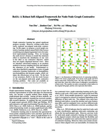
Chapter 1. IntroductionEach ThinkSystem SN550 compute node supports up to two 2.5-inch hot-swap Serial Attached SCSI (SAS),Serial ATA (SATA) or Non-Volatile Memory express (NVMe) hard disk drives.When you receive your Lenovo ThinkSystem SN550 Type 7X16 compute node, refer to the Setup Guide toset up the compute node, install optional devices, and perform the initial configuration of the compute node.Meanwhile, the Maintenance Manual contains information to help you solve problems that might occur inyour Lenovo ThinkSystem SN550 Type 7X16 compute node. It describes the diagnostic tools that come withthe compute node, error codes and suggested actions, and instructions for replacing failing components.The compute node comes with a limited warranty. For details about the warranty, uments/ht100742For details about your specific warranty, okupNotes:1. The first generation Chassis Management Module (CMM1; 68Y7030) is not supported by theThinkSystem SN550 compute node.2. The second generation Chassis Management Module (CMM2; 00FJ669) must be at firmware level 1.6.1or above to support the ThinkSystem SN550 compute node. This applies to both CMMs that areinstalled in the chassis.3. The illustrations in this document might differ slightly from your model.Identifying your compute nodeWhen you contact Lenovo for help, the machine type, model, and serial number information helps supporttechnicians to identify your compute node and provide faster service.Record information about the compute node in the following table.Table 1. Record of the system informationProduct nameMachine Type (s)Lenovo ThinkSystemSN550 Type 7X167X16Model numberSerial numberThe model number and serial number are on the ID label on the front of the compute node and the chassis,as shown in the following illustration.Note: The illustrations in this document might differ slightly from your hardware. Copyright Lenovo 20171
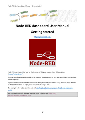
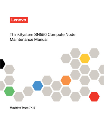
Figure 1. ID label on the front of the nodeTable 2. ID label on the front of the node1 ID labelCustomer information tabsThe customer information tabs contain system-related information such as firmware level, administratoraccounts and so forth.Figure 2. Location of customer information tabsSpecificationsThe following information is a summary of the features and specifications of the compute node. Dependingon the model, some features might not be available, or some specifications might not apply.2ThinkSystem SN550 Compute Node Maintenance Manual
Table 3. SpecificationsSpecificationDescriptionSize Height: 55.5 mm (2.2 in) Depth: 492.7 mm (19.4 in) Width: 215.5 mm (8.5 in)WeightApproximately 4.7 kg (10.4 lb) to 7.0 kg (15.5 lb), depending on your configuration.Processor (depending on themodel)Processor: Up to two multi-core Intel Xeon processors.Note: Use the Setup utility to determine the type and speed of the processors in thecompute node.For a list of supported processors, see: http://www.lenovo.com/serverproven/Memory 24 dual inline memory module (DIMM) connectors Type: Low-profile (LP) double-data rate (DDR4) DRAM Supports 8 GB, 16 GB, 32 GB and 64 GB DIMMs with up to 1.5 TB of totalmemory on the system board.Note: Future support is planned for the 128GB 3DS RDIMM. The total memory onthe system board may reach up to 3TB. Support for RDIMMs and LRDIMMs (combining is not supported)2.5-inch drive/backplane Supports up to two small form factor (SFF) drive bays. Drive bay can be eitherSATA only, SAS/SATA, or NVMe/SATA, depending on the model. Supported 2.5-inch drives:– Serial Attached SCSI (SAS)/Serial Advanced Technology Attachment (SATA)hot-swap hard disk drives/solid-state drives– Non-Volatile Memory Express (NVMe) solid-state drivesM.2 drive/backplaneThinkSystem M.2 with Mirroring Enablement Kit contains dual M.2 backplanesupports up to two identical M.2 drives.Supports 3 different physical sizes of M.2 drives: 42 mm (2242) 60 mm (2260) 80 mm (2280)RAID adapter RAID 530-4i adapter RAID 930-4i-2GB adapterIntegrated functions One baseboard management controller (BMC) with integrated VGA controller(XClarity Controller or XCC) Light path diagnostics Automatic server restart (ASR) Additional RAID levels supported when an optional RAID controller is installed One external USB 3.0 port Serial over LAN (SOL) Wake on LAN (WOL) when an optional I/O adapter with WOL capability is installed.Predictive failure analysis(PFA) alerts Processors Memory DrivesChapter 1. Introduction3
Table 3. Specifications (continued)SpecificationDescriptionSecurityFully compliant with NIST 800-131A. The security cryptography mode set by themanaging device (CMM or Lenovo XClarity Administrator) determines the securitymode in which the compute node operates.EnvironmentThe ThinkSystem SN550 compute node complies with ASHRAE Class A2specifications. Depending on the hardware configuration, some models comply withASHRAE Class A3 specifications. System performance may be impacted whenoperating temperature is outside ASHRAE A2 specification or fan failed condition.The Lenovo ThinkSystem SN550 compute node is supported in the followingenvironment: Air temperature:– Operating:– ASHRAE Class A2: 10 C - 35 C (50 F - 95 F); decrease the maximumambient temperature by 1 C for every 300 m (984 ft) increase in altitudeabove 900 m (2,953 ft)– ASHRAE Class A3: 5 C - 40 C (41 F - 104 F); decrease the maximumambient temperature by 1 C for every 175 m (574 ft) increase in altitudeabove 900 m (2,953 ft)– Compute node off: 5 C to 45 C (41 F to 113 F)– Shipment/Storage: -40 C to 60 C (-40 F to 140 F) Maximum altitude: 3,050 m (10,000 ft) Relative Humidity (non-condensing):– Operating:– ASHRAE Class A2: 8% - 80%, maximum dew point: 21 C (70 F)– ASHRAE Class A3: 8% - 85%, maximum dew point: 24 C (75 F)– Shipment/Storage: 8% - 90% Particulate contaminationAttention: Airborne particulates and reactive gases acting alone or in combinationwith other environmental factors such as humidity or temperature might pose arisk to the server. For information about the limits for particulates and gases, see“Particulate contamination” on page 122.Notes: Future support is planned for the single M.2 backplane function in the UEFI Setup page. Currently,users are unable to enable this functionality. This functionality is found in the following paths in the UEFIsetup page. F1 Setup System Settings Device and I/O Ports Enable/Disable Onboard Device(s) F1 Setup System Settings Device and I/O Ports Enable/Disable Adapter Option ROMSupport F1 Setup System Settings Device and I/O Ports Set Option ROM Execution OrderFirmware updatesSeveral options are available to update the firmware for the server.You can use the tools listed here to update the most current firmware for your server and the devices that areinstalled in the server.Note: Lenovo typically releases firmware in bundles called UpdateXpress System Packs (UXSPs). To ensurethat all of the firmware updates are compatible, you should update all firmware at the same time. If you areupdating firmware for both the Lenovo XClarity Controller and UEFI, update the firmware for Lenovo XClarityController first.4ThinkSystem SN550 Compute Node Maintenance Manual
Important terminology In-band update. The installation or update is performed using a tool or application within an operatingsystem that is executing on the server’s core CPU. Out-of-band update. The installation or update is performed by the Lenovo XClarity Controller collectingthe update and then directing the update to the target subsystem or device. Out-of-band updates have nodependency on an operating system executing on the core CPU. However, most out-of-band operationsdo require the server to be in the S0 (Working) power state. On-Target update. The installation or update is initiated from an Operating System executing on theserver’s operating system. Off-Target update. The installation or update is initiated from a computing device interacting directly withthe server’s Lenovo XClarity Controller. UpdateXpress System Packs (UXSPs). UXSPs are bundled updates designed and tested to provide theinterdependent level of functionality, performance, and compatibility. UXSPs are server machine-typespecific and are built (with firmware and device driver updates) to support specific Windows Server, RedHat Enterprise Linux (RHEL) and SUSE Linux Enterprise Server (SLES) operating system distributions.Machine-type-specific firmware-only UXSPs are also available.See the following table to determine the best Lenovo tool to use for installing and setting up the firmware:ToolLenovo update e Commandline interfaceSupportsUXSPs Limited to core systemfirmware only.Lenovo XClarityController Supports core systemfirmware and mostadvanced I/O optionfirmware updatesLenovo XClarityEssentials OneCLI Supports all coresystem firmware, I/Ofirmware, and installedoperating systemdriver updatesChapter 1. Introduction5
In-bandupdateToolLenovo XClarityEssentialsUpdateXpressOut-ofbandupdate eCommandline interfaceSupportsUXSPs Supports all coresystem firmware, I/Ofirmware, and installedoperating systemdriver updatesLenovo XClarityAdministrator Supports core systemfirmware and I/Ofirmware updatesThe latest firmware can be found at the following servers/thinksystem/sn550/7X16/downloads Lenovo XClarity Provisioning ManagerFrom Lenovo XClarity Provisioning Manager, you can update the Lenovo XClarity Controller firmware, theUEFI firmware, and the Lenovo XClarity Provisioning Manager software.Note: By default, the Lenovo XClarity Provisioning Manager Graphical User Interface is displayed whenyou press F1. If you have changed that default to be the text-based system setup, you can bring up theGraphical User Interface from the text-based system setup interface.Additional information about using Lenovo XClarity Provisioning Manager to update firmware is ic/LXPM/platform update.html Lenovo XClarity ControllerIf you need to install a specific update, you can use the Lenovo XClarity Controller interface for a specificserver.Notes:– To perform an in-band update through Windows or Linux, the operating system driver must be installedand the Ethernet-over-USB (sometimes called LAN over USB) interface must be enabled.Additional information about configuring Ethernet over USB is available novo.systems.management.xcc.doc/NN1ia cconfiguringUSB.html– If you update firmware through the Lenovo XClarity Controller, make sure that you have downloadedand installed the latest device drivers for the operating system that is running on the server.Specific details about updating firmware using Lenovo XClarity Controller are available novo.systems.management.xcc.doc/NN1ia cmanageserverfirmware.html Lenovo XClarity Essentials OneCLI6ThinkSystem SN550 Compute Node Maintenance Manual
Lenovo XClarity Essentials OneCLI is a collection of command line applications that can be used tomanage Lenovo servers. Its update application can be used to update firmware and device drivers foryour servers. The update can be performed within the host operating system of the server (in-band) orremotely through the BMC of the server (out-of-band).Specific details about updating firmware using Lenovo XClarity Essentials OneCLI is available tr cli lenovo/onecli c update.html Lenovo XClarity Essentials UpdateXpressLenovo XClarity Essentials UpdateXpress provides most of OneCLI update functions through a graphicaluser interface (GUI). It can be used to acquire and deploy UpdateXpress System Pack (UXSP) updatepackages and individual updates. UpdateXpress System Packs contain firmware and device driverupdates for Microsoft Windows and for Linux.You can obtain Lenovo XClarity Essentials UpdateXpress from the following n/solutions/ht503692 Lenovo XClarity AdministratorIf you are managing multiple servers using the Lenovo XClarity Administrator, you can update firmware forall managed servers through that interface. Firmware management is simplified by assigning firmwarecompliance policies to managed endpoints. When you create and assign a compliance policy to managedendpoints, Lenovo XClarity Administrator monitors changes to the inventory for those endpoints and flagsany endpoints that are out of compliance.Specific details about updating firmware using Lenovo XClarity Administrator are available novo.lxca.doc/update fw.htmlConfiguring the LAN over USB interface manuallyTo perform a firmware update through the operating system using Lenovo XClarity Essentials OneCLI, theLenovo XClarity Controller must be configured to use the LAN over USB interface. The firmware updatepackage attempts to perform the setup automatically, if needed. If the automatic setup fails or if you prefer toset up the LAN over USB manually, use one of the following procedures.Additional information about using the Lenovo XClarity Controller to enable LAN over USB is available novo.systems.management.xcc.doc/NN1ia cconfiguringUSB.htmlInstalling the LAN over USB Windows device driverWhen you install a Windows operating system, there might be an unknown RNDIS device in the DeviceManager. Lenovo provides a Windows INF file that identifies this device.Complete the following steps to install ibm rndis server os.inf:Note: You only have to perform these steps if the compute node is running a Windows operating system andthe ibm rndis server os.inf file has not been previously installed. The file only has to be installed once. It isrequired by Windows operating systems to detect and use the LAN over USB functionality.Step 1.Click Administrative Tools Computer Management Device Manager and find the RNDISDevice. Click Properties Driver Reinstall driver. Point the server to the \Windows\infdirectory where it can find the ibm rndis server os.inf file and install the device.Step 2.Click Administrative Tools Device Manager. Right-click Network adapters and select Scanfor hardware changes. A small pop-up confirms that the Ethernet device is found and installed.The New Hardware Wizard starts automatically.Chapter 1. Introduction7
Step 3.When you are prompted Can Windows connect to Windows Update to search for software?, select No,not this time. Click Next to continue.Step 4.When you are prompted What do you want the wizard to do?, select Install from a list or specificlocation (Advanced). Click Next to continue.Step 5.When you are prompted Please choose your search and installation options, select Don't search. Iwill choose the driver to install. Click Next to continue.Step 6.When you are prompted Select a hardware type, and then click Next, select Network adapters.Click Next to continue.Step 7.When you are prompted with the statement Completing the Found New Hardware Wizard, click Finish.A new local area connection appears. If the message This connection has limited or noconnectivity is displayed, ignore this message.Step 8.Return to the Device Manager. Lenovo USB Remote NDIS Network Device appears underNetwork Adapters.Step 9.Use the Lenovo XClarity Controller interface to view or set the IP address for the LAN adapter.Additional information about using the Lenovo XClarity Controller to configure LAN over USB isavailable novo.systems.management.xcc.doc/NN1ia cconfiguringUSB.htmlTech TipsLenovo continually updates the support website with the latest tips and techniques that you can use to solveissues that you might have with your compute node. These Tech Tips (also called retain tips or servicebulletins) provide procedures to work around issues related to the operation of your compute node.To find the Tech Tips available for your compute node:1. Go to http://datacentersupport.lenovo.com and navigate to the support page for your compute node.2. Click How-tos & Solutions.Expand Symptom to choose a category for the type is problem that you are having.Security advisoriesLenovo is committed to developing products and services that adhere to the highest security standards inorder to protect our customers and their data. When potential vulnerabilities are reported, it is theresponsibility of the Lenovo Product Security Incident Response Team (PSIRT) to investigate and provideinformation to our customers so they may put mitigation plans in place as we work toward providingsolutions.The list of current advisories is available at the following oduct security/homePower on the compute nodeUse this information for details about power on the compute node.After you connect the compute node to power through the Lenovo Flex System chassis, the compute nodecan be started in any of the following ways.8ThinkSystem SN550 Compute Node Maintenance Manual
Important: If an Attention label is on the front panel of the compute node above the power button, read it;then, remove the label and discard it before turning on the compute node. You can press the power button on the front of the compute node to start the compute node. The powerbutton works only if local power control is enabled for the compute node. Local power control is enabledand disabled through the CMM power command and the CMM web interface.– For more information about the CMM power command, see the Flex System Chassis ManagementModule: Command-Line Interface Reference Guide at enovo.acc.cmm.doc/cli command power.html.– From the CMM web interface, select Compute Nodes from the Chassis Management menu. Formore information, see the "Flex System Chassis Management Module: User's Guide" at enovo.acc.cmm.doc/cmm user guide.html. All fields andoptions are described in the CMM web interface online help.Notes:1. Wait until the power LED on the compute node flashes slowly before you press the power button.While the Lenovo XClarity Controller in the compute node is initializing and synchronizing with theChassis Management Module, the power LED flashes rapidly, and the power button on the computenode does not respond. The time required for a compute node to initialize varies by systemconfiguration; however, the power LED blink rate slows when the compute node is ready to be turnedon.2. While the compute node is starting, the power LED on the front of the compute node is lit and doesnot flash. If a power failure occurs, the Lenovo Flex System chassis and the compute node can be configuredthrough the CMM power command and the CMM web interface to start automatically when power isrestored.– For more information about the CMM power command, see the Flex System Chassis ManagementModule: Command-Line Interface Reference Guide at enovo.acc.cmm.doc/cli command power.html.– From the CMM web interface, select Compute Nodes from the Chassis Management menu. Formore information, see the "Flex System Chassis Management Module: User's Guide" at enovo.acc.cmm.doc/cmm user guide.html. All fields andoptions are described in the CMM web interface online help. You can turn on the compute node through the CMM power command, the CMM web interface and theLenovo XClarity Administrator application (if installed).– For more information about the CMM power command, see the Flex System Chassis ManagementModule: Command-Line Interface Reference Guide at enovo.acc.cmm.doc/cli command power.html.– From the CMM web interface, select Compute Nodes from the Chassis Management menu. Formore information, see the "Flex System Chassis Management Module: User's Guide" at enovo.acc.cmm.doc/cmm user guide.html. All fields andoptions are des
Returning a device or component . . . . . . 23 Updating the compute node configuration . . 23 Compute node replacement . . 2 ThinkSystem SN550 Compute Node Maintenance Manual. Table 3. Specifications Specification Description Size Height: 55.5 mm (2.2 in) Depth: 492.7 mm (19.4 in)