Transcription
SULLAIR INDUSTRIALAIR COMPRESSOR3000, 3700, 4500,3000V, 3700V, 4500V30, 37 & 45 KW/40, 50 & 60HPAir-Cooled Standard & 24 KTPART NUMBER:02250155-601KEEP FORFUTUREREFERENCE SULLAIR CORPORATIONStarting Serial Number:Manual Brought to You By: IndustrialAirPower.com003-139556O PERATO R’S M ANU AL AND PARTS LIST
AIR CARESEMINAR TRAININGSullair Air Care Seminars are courses that provide hands-on instruction in the proper operation, maintenanceand service of Sullair equipment. Individual seminars on Industrial compressors and compressor electricalsystems are presented at regular intervals throughout the year at a dedicated training facility at Sullair'scorporate headquarters in Michigan City, Indiana.Instruction includes discussion of the function and installation of Sullair service parts, troubleshooting of themost common problems, and actual equipment operation. The seminars are recommended for maintenanceand service personnel.For detailed course outlines, schedule and cost information contact:Sullair Corporate Training Department: 1-888-SULLAIR or219-879-5451 (ext. 5363)www.sullair.com- Or Write Sullair Corporation3700 E. Michigan Blvd.Michigan City, IN 46360Attn: Service Training Department
SULLAIR 3700 Operator’s Manual and Parts ListTABLE OF CONTENTS1 - SAFETY . 1General. 1Personal Protective Equipment . 1Pressure Release. 2Fire and Explosion. 2Moving Parts . 3Hot Surfaces, Sharp Edges and Sharp Corners . 3Toxic and Irritating Substances . 3Electrical Shock. 4Lifting. 4Entrapment. 52 - DESCRIPTION. 7Introduction. 7Description of Components . 8Sullair Compressor Unit, Functional Description. 8Compressor Cooling and Lubrication System, FunctionalDescription . 10Compressor Discharge System, Functional Description . 10Control System, Functional Description . 11START MODE - 0 TO 50 PSIG(0 TO 3.5 BAR). 11FULL LOAD MODE - 50 TO 100 PSIG (3.4 TO 6.9 BAR). 12MODULATING MODE - 100 TO 110 PSIG (6.9 TO 7.6 BAR) . 12UNLOAD MODE - IN EXCESS OF 110 PSIG (7.6 BAR) . 13LOAD/NO LOAD CONTROL . 13AUTOMATIC OPERATION . 13Air Inlet System, Functional Description. 133 - SPECIFICATIONS . 15Table of Specifications . 15Lubrication Guide . 17 SULLAIR 3700 Operator’s Manual and Parts Listiii
Application Guide . 17Lubrication Change Recommendations and Maintenance Fluid Filter and Separator. 184 - INSTALLATION. 25Mounting of Compressor . 25Ventilation and Cooling . 25Air-Cooled Compressors . 25Service Air Piping .Pipe Sizing .Use of Auxiliary Receiver / Sump.Isolation Valve(s).Fluid Containment .2626262627Coupling Alignment Check . 27Fluid Level Check. 27Electrical Preparation . 27Motor Rotation Direction Check . 28Fan Motor Rotation Check . 285 - WS Controller . 29Controller Layout . 29Controller Keypad. 29LED Display. 29LED Lights. 316 - MAINTENANCE . 33General. 33Daily Operation. 33Maintenance After Initial 50 Hours of Operation . 33Maintenance Every 2000 Hours . 33Fluid Maintenance . 34Filter Maintenance. 34Fluid Filter Element Replacement . 34Air Filter Maintenance . 34Air Filter Element Replacement. 35Separator Maintenance .Separator Element Replacement .Oil Return/Sight Glass Maintenance .Pressure Regulator Adjustment .Water Condensate Drain Maintenance .Control Line Strainer .Shaft Coupling Maintenance .35353536363637Troubleshooting - Introduction. 37Troubleshooting Guide . 38iv3700 Operator’s Manual and Parts List SULLAIR
TABLE OF CONTENTS7 - PARTS LISTS. 41Procedure For Ordering Parts . 41Recommended Spare Parts List . 43Compressor, Frame and Drive - 3000 and 3700 Models . 44Compressor, Frame and Drive - 4500 Model . 46Air Inlet System . 48Air Piping - Air-Cooled. 50Fluid Piping - Air-Cooled . 52Cooling and Lubrication System - Air-Cooled 18"/60HzFan, Standard Cooler . 54Discharge, Sump and Piping System. 56Moisture Drain . 58Pneumatic Control System - Standard . 60Pneumatic Control System - With Sequencing . 62Control System and Electric Parts - 230/460WYE-Delta. 64Enclosure - Air-Cooled . 66Decal Section - Air-Cooled . 68 SULLAIR 3700 Operator’s Manual and Parts Listv
This Page Intentionally Left Blankvi3700 Operator’s Manual and Parts List SULLAIR
SULLAIR 3700 Operator’s Manual and Parts ListSection 1SAFETYInstall, use and operate the compressor only in fullcompliance with all pertinent OSHA regulations and/orany applicable Federal, State, and Local codes,standards and regulations.NOTEDO NOT modify the compressor and/or controls in anyway except with written factory approval.OPERATOR IS REQUIRED TOREAD ENTIRE INSTRUCTIONMANUAL.SU 00000051.1 GENERALSullair Corporation and its subsidiaries design andmanufacture all of their products so they can beoperated safely. However, the responsibility for safeoperation rests with those who use and maintain theseproducts. The following safety precautions are offered asa guide which, if conscientiously followed, will minimizethe possibility of accidents throughout the useful life ofthis equipment.The compressor should be operated only by those whohave been trained and delegated to do so, and who haveread and understood this Operator’s Manual. Failure tofollow the instructions, procedures and safetyprecautions in this manual may result in accidents andinjuries.While not specifically applicable to all types ofcompressors with all types of prime movers, most of theprecautionary statements contained herein areapplicable to most compressors and the conceptsbehind these statements are generally applicable to allcompressors.1.2 PERSONAL PROTECTIVEEQUIPMENTPrior to installing or operating the compressor, owners,employers and users should become familiar with, andcomply with, all applicable OSHA regulations and/or anyapplicable Federal, State and Local codes, standards,and regulations relative to personal protectiveequipment, such as eye and face protective equipment,respiratory protective equipment, equipment intended toprotect the extremities, protective clothing, protectiveshields and barriers and electrical protective equipment,as well as noise exposure administrative and/orengineering controls and/or personal hearing protectiveequipment.NEVER start the compressor unless it is safe to do so.DO NOT attempt to operate the compressor with aknown unsafe condition. Tag the compressor and renderit inoperative by disconnecting and locking out all powerat source or otherwise disabling its prime mover soothers who may not know of the unsafe condition cannotattempt to operate it until the condition is corrected. SULLAIR 3700 Operator’s Manual and Parts List1
SECTION 11.3 PRESSURE RELEASEA. Install an appropriate flow-limiting valve betweenthe service air outlet and the shut-off (throttle)valve, either at the compressor or at any otherpoint along the air line, when an air hoseexceeding 13mm inside diameter is to beconnected to the shut-off (throttle) valve, toreduce pressure in case of hose failure, perOSHA Standard 29 CFR 1926.302(b)(7) and/orany applicable Federal, State and Local codes,standards and regulations.B. When the hose is to be used to supply a manifold,install an additional appropriate flow-limiting valvebetween the manifold and each air hoseexceeding 13mm inside diameter that is to beconnected to the manifold to reduce pressure incase of hose failure.C. Provide an appropriate flow-limiting valve at thebeginning of each additional 23m of hose in runsof air hose exceeding 13mm inside diameter toreduce pressure in case of hose failure.D. Flow-limiting valves are listed by pipe size andflow-rated. Select appropriate valves accordingly,in accordance with their manufacturer’srecommendations.E. DO NOT use air tools that are rated below themaximum rating of the compressor. Select airtools, air hoses, pipes, valves, filters and otherfittings accordingly. DO NOT exceedmanufacturer’s rated safe operating pressures forthese items.F. Secure all hose connections by wire, chain orother suitable retaining device to prevent tools orhose ends from being accidentally disconnectedand expelled.G. Open fluid filler cap only when compressor is notrunning and is not pressurized. Shut down thecompressor and bleed the sump (receiver) to zerointernal pressure before removing the cap.H. Vent all internal pressure prior to opening any line,fitting, hose, valve, drain plug, connection or othercomponent, such as filters and line oilers, andbefore attempting to refill optional air line anti-icersystems with antifreeze compound.I. Keep personnel out of line with and away from thedischarge opening of hoses or tools or otherpoints of compressed air discharge.J. Use air at pressures less than 2.1 bar for cleaningpurposes, and then only with effective chipguarding and personal protective equipment perOSHA Standard 29 CFR 1910.242 (b) and/or anyapplicable Federal, State, and Local codes,standards and regulations.2K. DO NOT engage in horseplay with air hoses asdeath or serious injury may result.1.4 FIRE AND EXPLOSIONA. Clean up spills of lubricant or other combustiblesubstances immediately, if such spills occur.B. Shut off the compressor and allow it to cool. Thenkeep sparks, flames and other sources of ignitionaway and DO NOT permit smoking in the vicinitywhen checking or adding lubricant or whenrefilling air line anti-icer systems with antifreezecompound.C. DO NOT permit fluids, including air line anti-icersystem antifreeze compound or fluid film, toaccumulate on, under or around acousticalmaterial, or on any external surfaces of the aircompressor. Wipe down using an aqueousindustrial cleaner or steam clean as required. Ifnecessary, remove acoustical material, clean allsurfaces and then replace acoustical material.Any acoustical material with a protective coveringthat has been torn or punctured should bereplaced immediately to prevent accumulation ofliquids or fluid film within the material. DO NOTuse flammable solvents for cleaning purposes.D. Disconnect and lock out all power at source priorto attempting any repairs or cleaning of thecompressor or of the inside of the enclosure, ifany.E. Keep electrical wiring, including all terminals andpressure connectors in good condition. Replaceany wiring that has cracked, cut, abraded orotherwise degraded insulation, or terminals thatare worn, discolored or corroded. Keep allterminals and pressure connectors clean andtight.F. Keep grounded and/or conductive objects such astools away from exposed live electrical parts suchas terminals to avoid arcing which might serve asa source of ignition.G. Remove any acoustical material or other materialthat may be damaged by heat or that may supportcombustion and is in close proximity, prior toattempting weld repairs.H. Keep suitable fully charged Class BC or ABC fireextinguisher or extinguishers nearby whenservicing and operating the compressor.I. Keep oily rags, trash, leaves, litter or othercombustibles out of and away from thecompressor.J. DO NOT operate the compressor without properflow of cooling air or water or with inadequate flowof lubricant or with degraded lubricant.3700 Operator’s Manual and Parts List SULLAIR
SAFETYK. DO NOT attempt to operate the compressor inany classification of hazardous environmentunless the compressor has been speciallydesigned and manufactured for that duty.A DANGER1.5 MOVING PARTSA. Keep hands, arms and other parts of the bodyand also clothing away from couplings, fans andother moving parts.B. DO NOT attempt to operate the compressor withthe fan, coupling or other guards removed.C. Wear snug-fitting clothing and confine long hairwhen working around this compressor, especiallywhen exposed to hot or moving parts.D. Keep access doors, if any, closed except whenmaking repairs or adjustments.E. Make sure all personnel are out of and/or clear ofthe compressor prior to attempting to start oroperate it.F. Disconnect and lock out all power at source andverify at the compressor that all circuits are deenergized to minimize the possibility of accidentalstart-up, or operation, prior to attempting repairsor adjustments. This is especially important whencompressors are remotely controlled.G. Keep hands, feet, floors, controls and walkingsurfaces clean and free of fluid, water or otherliquids to minimize the possibility of slips and falls.1.6 HOT SURFACES, SHARP EDGESAND SHARP CORNERSA. Avoid bodily contact with hot fluid, hot coolant, hotsurfaces and sharp edges and corners.B. Keep all parts of the body away from all points ofair discharge.C. Wear personal protective equipment includinggloves and head covering when working in, on oraround the compressor.D. Keep a first aid kit handy. Seek medicalassistance promptly in case of injury. DO NOTignore small cuts and burns as they may lead toinfection.INHALATION HAZARD!Death or serious injury can result frominhaling compressed air without usingproper safety equipment. See OSHAstandards and/or any applicable Federal,State, and Local codes, standards andregulations on safety equipment.SU 0000006B. DO NOT use air line anti-icer systems in air linessupplying respirators or other breathing airutilization equipment and DO NOT discharge airfrom these systems into unventilated or otherconfined areas.C. Operate the compressor only in open oradequately ventilated areas.D. Locate the compressor or provide a remote inletso that it is not likely to ingest exhaust fumes orother toxic, noxious or corrosive fumes orsubstances.E. Coolants and lubricants used in this compressorare typical of the industry. Care should be taken toavoid accidental ingestion and/or skin contact. Inthe event of ingestion, seek medical treatmentpromptly. Wash with soap and water in the eventof skin contact. Consult Material Safety DataSheet for information pertaining to fluid of fill.F. Wear goggles or a full face shield when addingantifreeze compound to air line anti-icer systems.G. If air line anti-icer system antifreeze compoundenters the eyes or if fumes irritate the eyes, theyshould be washed with large quantities of cleanwater for fifteen minutes. A physician, preferablyan eye specialist, should be contactedimmediately.H. DO NOT store air line anti-icer system antifreezecompound in confined areas.1.7 TOXIC AND IRRITATINGSUBSTANCESA. DO NOT use air from this compressor forrespiration (breathing) except in full compliancewith OSHA Standards 29 CFR 1910 and/or anyapplicable Federal, State or Local codes orregulations. SULLAIR 3700 Operator’s Manual and Parts List3
SECTION 1I. The antifreeze compound used in air lineantifreeze systems contains methanol and istoxic, harmful or fatal if swallowed. Avoid contactwith the skin or eyes and avoid breathing thefumes. If swallowed, induce vomiting byadministering a tablespoon of salt, in each glassof clean, warm water until vomit is clear, thenadminister two teaspoons of baking soda in aglass of clean water. Have patient lay down andcover eyes to exclude light. Call a physicianimmediately.1.8 ELECTRICAL SHOCKA. This compressor should be installed andmaintained in full compliance with all applicableFederal, State and Local codes, standards andregulations, including those of the NationalElectrical Code, and also including those relativeto equipment grounding conductors, and only bypersonnel that are trained, qualified anddelegated to do so.B. Keep all parts of the body and any hand-held toolsor other conductive objects away from exposedlive parts of electrical system. Maintain dryfooting, stand on insulating surfaces and DO NOTcontact any other portion of the compressor whenmaking adjustments or repairs to exposed liveparts of the electrical system. Make all suchadjustments or repairs with one hand only, so asto minimize the possibility of creating a currentpath through the heart.C. Attempt repairs in clean, dry and well lighted andventilated areas only.D. DO NOT leave the compressor unattended withopen electrical enclosures. If necessary to do so,then disconnect, lock out and tag all power atsource so others will not inadvertently restorepower.E. Disconnect, lock out, and tag all power at sourceprior to attempting repairs or adjustments torotating machinery and prior to handling anyungrounded conductors.A DANGERAll field equipment must be tested forelectrostatic fields prior to servicing ormaking contact with the machine usingthe following or equivalent testequipment: 90-600 VAC: Volt detector such as FlukeModel 1AC-A 600-7000 VAC: Voltage detector such asFluke Networks Model C9970It is the responsibility of eachorganization to provide/arrange trainingfor all their associates expected to test forelectrostatic fields.SU 00000201.9 LIFTINGA. If the compressor is provided with a lifting bail,then lift by the bail provided. If no bail is provided,then lift by sling. Compressors to be air-lifted byhelicopter must not be supported by the lifting bailbut by slings instead. In any event, lift and/orhandle only in full compliance with OSHAstandards 29 CFR 1910 subpart N and/or anyapplicable Federal, State, and Local codes,standards and regulations.B. Inspect points of attachment for cracked weldsand for cracked, bent, corroded or otherwisedegraded members and for loose bolts or nutsprior to lifting.C. Make sure entire lifting, rigging and supportingstructure has been inspected, is in good conditionand has a rated capacity of at least the weight ofthe compressor. If you are unsure of the weight,then weigh compressor before lifting.D. Make sure lifting hook has a functional safetylatch or equivalent, and is fully engaged andlatched on the bail or slings.E. Use guide ropes or equivalent to prevent twistingor swinging of the compressor once it has beenlifted clear of the ground.F. DO NOT attempt to lift in high winds.G. Keep all personnel out from under and away fromthe compressor whenever it is suspended.H. Lift compressor no higher than necessary.I. Keep lift operator in constant attendancewhenever compressor is suspended.J. Set compressor down only on a level surfacecapable of safely supporting at least its weightand its loading unit.43700 Operator’s Manual and Parts List SULLAIR
SAFETYK. When moving the compressor by forklift truck,utilize fork pockets if provided. Otherwise, utilizepallet if provided. If neither fork pockets or palletare provided, then make sure compressor issecure and well balanced on forks beforeattempting to raise or transport it any significantdistance.L. Make sure forklift truck forks are fully engagedand tipped back prior to lifting or transporting thecompressor.M. Forklift no higher than necessary to clearobstacles at floor level and transport and corner atminimum practical speeds.N. Make sure pallet-mounted compressors are firmlybolted or otherwise secured to the pallet prior toattempting to forklift or transport them. NEVERattempt to forklift a compressor that is not securedto its pallet, as uneven floors or sudden stops maycause the compressor to tumble off, possiblycausing serious injury or property damage in theprocess.1.10 ENTRAPMENTA. If the compressor enclosure, if any, is largeenough to hold a man and if it is necessary toenter it to perform service adjustments, informother personnel before doing so, or else secureand tag the access door in the open position toavoid the possibility of others closing and possiblylatching the door with personnel inside.B. Make sure all personnel are out of compressorbefore closing and latching enclosure doors. SULLAIR 3700 Operator’s Manual and Parts List5
SECTION 1This Page Intentionally Left Blank63700 Operator’s Manual and Parts List SULLAIR
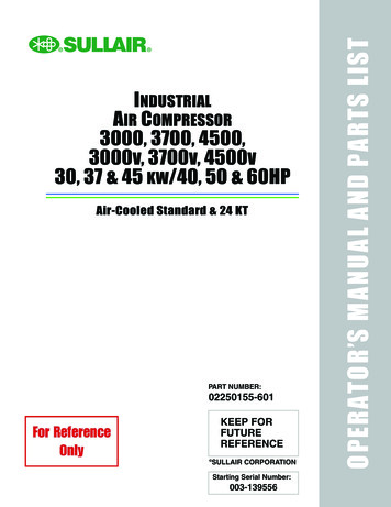
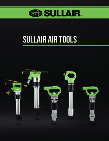
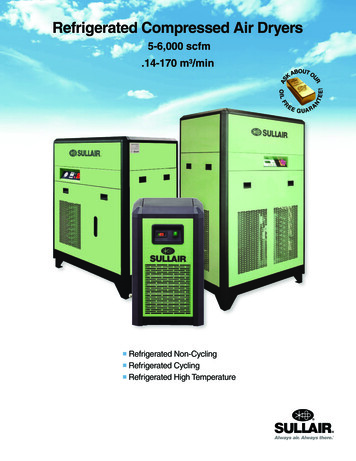
SULLAIR 3700 Operator’s Manual and Parts ListSection 2DESCRIPTION2.1 INTRODUCTIONCompared to other types of compressors, the Sullairrotary screw is unique in mechanical reliability, with “nowear” and “no inspection” required of the working partswithin the compressor unit.Your new Sullair flood-lubricated rotary screw aircompressor will provide you with a unique experience inimproved reliability and simplified maintenance.Read Section 6, MAINTENANCE to see howsurprisingly easy it is to keep your air compressor in topoperating condition.Figure 2-1 3!? 1.2.3.4.5.6.7.Fluid FilterMoisture SeparatorSump TankFluid Fill Sight GlassFluid FillStarter BoxController8.9.10.11.12.13.E-Stop ButtonCompressor UnitCooler Fan MotorCoolerMotorAir Inlet FilterFigure 2-1Overall Component Layout - Air-Cooled Model SULLAIR 3700 Operator’s Manual and Parts List7
SECTION 22.2 DESCRIPTION OF COMPONENTSRefer to Figure 2-1 and Figure 2-2. The componentsand assemblies of the air compressor are clearly shown.The complete package includes compressor, electricmotor, starter, compressor inlet system,compressor discharge system, compressorlubrication and cooling system, capacity controlsystem, microprocessor controller, aftercooler, acombination separator and trap, all mounted on aheavy gauge steel frame.On air-cooled models, a fan draws air into the enclosureover the fan and main motors through the combinedaftercooler and fluid cooler thereby removing thecompression heat from the compressed air and thecooling fluid, and forces it out the top of the machine.On water-cooled models, a shell and tube heatexchanger is mounted on the compressor frame. Fluid ispiped into the heat exchanger where compression heatis removed from the fluid. Another similar heatexchanger cools the compressed air.Both air-cooled and water-cooled versions have easilyaccessible items such as the fluid filter air/oil separatorand control valves. The inlet air filter is also easilyaccessible for servicing.Sullair recommends that a 24KT sample be taken at thefirst filter change and sent to the factory for analysis.This is a free service. The sample kit with instructionsand self-addressed container is to be supplied by yourSullair dealer at start-up. The user will receive ananalysis report with recommendations.Fluid is injected into the compressor unit hoses andmixes directly with the air as the rotors turn,compressing the air. The fluid flow has three basicfunctions:1. As coolant, it controls the rise of air temperaturenormally associated with the heat of compression.2. Seals the clearance paths between the rotors andthe stator and also between the rotors themselves.3. Acts as a lubricating film between the rotors allowingone rotor to directly drive the other, which is an idler.After the air/fluid mixture is discharged from thecompressor unit, the fluid is separated from theair. At this time, the air flows through anaftercooler and separator then to your serviceline while the fluid is being cooled in preparationfor reinjection.2.3 SULLAIR COMPRESSOR UNIT,FUNCTIONAL DESCRIPTIONSullair air compressors feature the Sullair compressorunit, a single-stage, positive displacement, floodlubricated-type compressor. This unit providescontinuous compression to meet your needs.NOTEWith a Sullair compressor, there is nomaintenance or inspection of the internalparts of the compressor unit permitted inaccordance with the terms of thewarranty.SU 0000021The 3700 Series compressors are factory-filled withSullube lubricant. For more information on fluid fill,consult Section 3, SPECIFICATIONS.Sullair 24KT compressors are filled with a fluid thatrarely needs to be changed. Use only Sullair 24KT fluidin the event that a fluid change is required.CAUTIONMixing of other lubricants within thecompressor unit will void all warranties.SU-000002283700 Operator’s Manual and Parts List SULLAIR
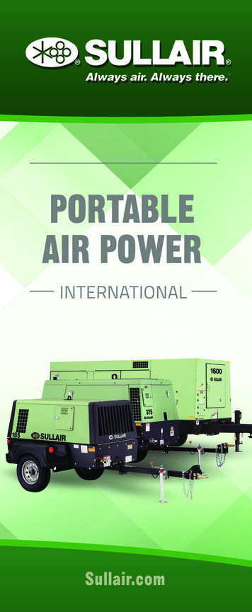
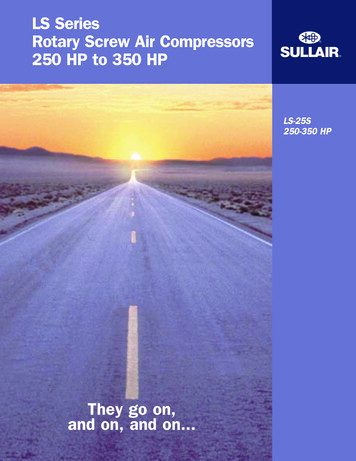
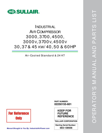
DESCRIPTIONFigure 2-2COOLING / LUBRICATIONSYSTEMDISCHARGE SYSTEMSA 0000009Figure 2-2Air-Cooled Cooling/Lubrication and Discharge System SULLAIR 3700 Operator’s Manual and Parts List9
SECTION 22.4 COMPRESSOR COOLING ANDLUBRICATION SYSTEM,FUNCTIONAL DESCRIPTIONRefer to Figure 2-2. The Cooling and LubricationSystem (air-cooled version) consists of a fan, fanmotor, radiator-type aftercooler/fluid cooler, full flowfluid filter, thermal valve, and interconnecting hoses.For water-cooled models, two shell and tube heatexchangers and a water-flow regulating valve aresubstituted for the radiator-type cooler listed above. Thepressure in the receiver/sump causes fluid flow byforcing the fluid from the high pressure area of the sumpto an area of lower pressure in the compressor unit.Fluid flows from the bottom of the receiver/sump to thethermal valve. The thermal valve is fully open when thefluid temperature is below 185 F (85 C) [200 F (93 C)for 24KT] and pressures are rated at or above 150 psig.The fluid passes through the thermal valve, the mainfilter and directly to the compressor unit where itlubricates, cools and seals the rotors and thecompression chamber.As the discharge temperature rises above 185 F (85 C),due to the heat of compression, the thermal valv
keep for future reference operator's manual and parts list sullair part number: sullair corporation starting serial number: 003-139556 industrial air compressor 3000, 3700, 4500, 3000v, 3700v, 4500v 30, 37 & 45 kw/40, 50 & 60hp air-cooled standard & 24 kt