Transcription
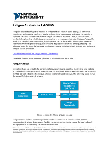
FATIGUE FAILURE AND TESTING METHODSBachelor’s thesisMECHANICAL ENGINEERING AND PRODUCTION TECHNOLOGYRiihimäki, 15/05/2013ABASS ADEYINKA AZEEZ
Fatigue Failure and Testing MethodsABSTRACTRiihimäkiMechanical Engineering and Production TechnologyMechatronicsAuthorABASS ADEYINKA AZEEZYear 2013Bachelor’s thesisFATIGUE FAILURE AND TESTING METHODABSTRACTThe aim of this thesis work is to discuss the principle of fatigue failure, research the state of the art fatigue testing methods and finally design a verification fatigue test set-up to evaluate the performance of the newly developed dynamic testing machine in the mechatronics laboratory of HAMKUniversity of applied sciences.A comprehensive study of the underlying principle, stages and numerousfactors that makes fatigue such a complex phenomenon was carried out.This was closely followed by research work on the standard fatigue testingmethods and statistical analysis of fatigue test results.Based on the knowledge gained from the research work stated above, afour-point fully reversed bending set-up design was developed to put intotest the functionality of the dynamic testing machine once it is ready to runand also a planned fatigue test suitable for laboratory exercise in a materialscience or engineering design class was developed.KeywordsFatigue Failure, Fatigue Testing Methods and 4-point bending set-up.Pages32 p. appendix1
Fatigue Failure and Testing MethodsBACHALOR THESISTable of Contents1 INTRODUCTION . 32 FATIGUE AS A PHENOMENON IN THE MATERIAL . 42.1 General . 42.2 Different phases of fatigue life . 52.2.1 Crack initiation (Ni) . 62.2.2 Crack growth Np . 62.2.3 Rapid fracture . 62.3 Fatigue Properties of Materials . 62.4 Design for fatigue failure . 82.4.1 Corrected fatigue strength . 82.4.2 Selection of materials for fatigue resistance . 93 FATIGUE TESTING METHODS . 113.1 Classification based on the sequence of stress amplitudes . 113.1.1 Constant-amplitude test . 113.1.2 Variable-amplitude tests . 123.2 Classification based on the nature of the test-piece . 133.2.1 Specimens . 133.2.2 Component . 143.3 General Classification of Fatigue Testing . 153.3.1 Material type test . 153.3.2 Structural type test . 163.3.3 Actual service type test . 164 FATIGUE TESTING MACHINE . 174.1 Classification of fatigue testing machine . 174.2 General purpose testing machine . 174.2.1 Classification based on type of stressing method . 174.3 Components of a fatigue testing machine . 204.4 The testing machine of HAMK University, mechatronic laboratory . 214.5 Design of the testing support structure . 225 COLLECTION, ANALYSIS AND PRESENTATION OF FATIGUE DATA. 245.1 Analysis and determination of finite life . 255.2 Staircase method . 256 A PLANNED FATIGUE TEST . 276.1 General . 276.2 Fatigue test exercise . 287 CONCLUSION . 292
Fatigue Failure and Testing Methods1INTRODUCTIONA perusal of the broken parts in almost any scrap will show that a high number of failures occur at stresses below the yield strength of the part s materials. This complexphenomenon is known as “Fatigue”. Fatigue is responsible for up to 90% of the inservice part failure which occur in industry.In the 19th century, it was considered mysterious that a fatigue fracture did not showvisible plastic deformation, this lead to an erroneous believe that fatigue was merely anengineering problem. Well, they were not so wrong since the power of microscopicequipment of that time was quite limited, also during this century few fatigue tests werecarried out by notable researchers; most popular was the work of August Wöhler, wholater come up with the idea of stress-lifetime curve (S-N Curve).A major breakthrough in the understanding of the process of fatigue failure happened inthe 20th century. Thanks to more powerful tools such as computer, powerful microscopic instrument, advance numerical analysis methods and much more research work (asmuch as 100,000 references was cited by John Mann in one of his works), fatigue beganto be viewed not as an engineering problem but as both material and design phenomenon.Despite the large amount of research carried out on fatigue failure, its true nature stillremains unknown and damage, cracks or even complete failure due to cycling loads areconstantly been reported. If the problem still exists after 100 years of research in theprevious century, there is something to be explained.The idea behind this thesis work is not to provide answers to the unanswered questions, but to tackle the problem from a different perspective. This includes explainingthe complex nature of fatigue failure, introduce basic idea of engineering design againstfatigue failure, explain the known techniques of fatigue testing, set-up a verification testfor the servo-hydraulic dynamic testing machine (still under construction) in the mechatronics laboratory of HAMK University of Applied Sciences and also plan a laboratoryfatigue test exercise suitable for a machine design or material science courseware.3
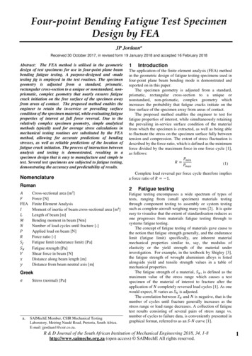
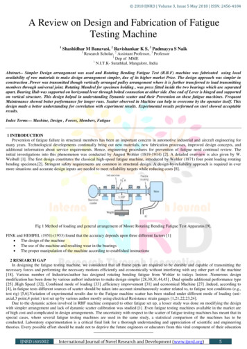
Fatigue Failure and Testing Methods22.1FATIGUE AS A PHENOMENON IN THE MATERIALGeneralFatigue is the condition whereby a material cracks or fails because of repeated (cyclic)stresses applied below the ultimate strength of the material. Fatigue failure often occursquite suddenly with catastrophic result.When a structure is loaded, a crack will be nucleated (crack nucleation) on a microscopically small scale, this crack then grows (crack growth), then finally complete failure ofthe specimen. The whole process constitutes the fatigue life of the component in question. According to Jaap Schijve, Reasonable fatigue prediction for design or analysiscan only be done if fatigue is viewed not only as an engineering problem but also a material phenomenon that is a process involving an invisible micro scale crack initiationtill a macro scale fatigue failure.To this ends, the underlying stages of fatigue life of a component will be discussed aswell as important fatigue properties of common materials and also the basic principle ofdesign against fatigue failure.Figure 1Survey of the various aspects of fatigue of structures [3].4
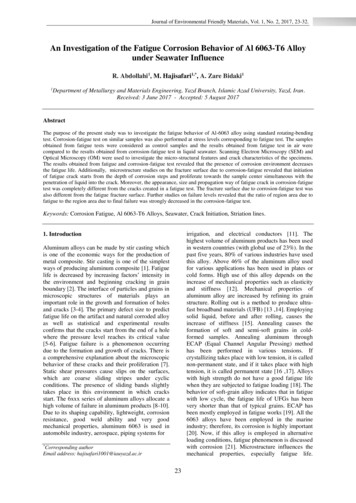
Fatigue Failure and Testing Methods2.2Different phases of fatigue lifeMicroscopic investigation in the 20th century has revealed that the nucleation of fatiguecracks occurs at a very early stage of fatigue life. The crack starts as a slip band within agrain. The cyclic slip occurs as a result of cyclic shear stress, this slip leads to formationof slip steps, in the present of oxygen, the freshly exposed surface of the material in slipsteps get oxidized, which prevents slip reversal. The slip reversal in this case occurs insome adjacent slip plane, thereby leading to formation of extrusions and intrusions onthe surface of the material as shown in the figure below.Figure 2Formation of intrusion and extrusion marks on the material surfaceThe fatigue life is generally divided into three stages/periodsFigure 3Different phases of the fatigue lifeThe fatigue life (Nf) of a component is defined by the total number of stress cycles required to cause failure. Fatigue life can be separated into three stages where:Nf Ni Np(1)5
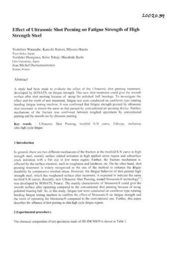
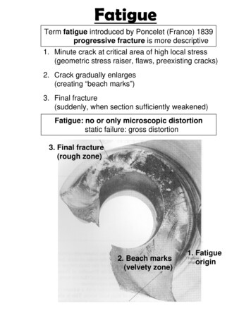
Fatigue Failure and Testing Methods2.2.1 Crack initiation (Ni)This is the number of cycles required to initiate a crack. It generally results from dislocation pile-ups and imperfections such as surface roughness, voids, scratch etc. hence;in this period fatigue is a material surface phenomenon.The stress concentration factor, Kt is another factor to be considered in crack initiationprediction.2.2.2 Crack growth NpThis is the number of cycles required to grow the crack in a stable manner to a criticalsize, generally controlled by stress level. Since most common material contains flaws,the prediction of crack growth is the most studied aspect of fatigue. Crack growth resistance, when the crack penetrates into the material, depends on the material as a bulkproperty. It is no longer a surface phenomenon. The stress intensity factor is an important factor for fatigue growth prediction.2.2.3 Rapid fractureVery rapid critical crack growth occurs when the crack length reaches a critical value.Since rapid fracture occurs quickly, there is no rapid fracture term in the fatigue lifeexpression.The fracture toughness KIC of the material is the primary factor for rapid fracture prediction or design against fracture.2.3Fatigue Properties of MaterialsFatigue is generally understood as the gradual deterioration of a material which is subjected to cyclic loads. In fatigue testing, a specimen is subjected to periodically varyingconstant amplitude stress. The applied stresses may alternate between equal positive andnegative value from zero to maximum positive or negative value, or between equal positive and negative values or between unequal positive and negative values.A series of fatigue tests are made on a number of specimens of the material at differentstress levels. The stress endured is then plotted against the number of cycle sustained.By choosing lower and lower stresses, a value may be found which will not producefailure, regardless of the number of applied cycle. This stress value is called the fatiguelimit of the material or the endurance limit. The plot of the two terms is called stresscycle diagram or S-N diagram. The fatigue limit may be established for most steels between 2 and 10 million cycles. Non-ferrous metals such as aluminum usually show noclearly defined fatigue limit. (Mark s Standard-Handbook/Strength of Materials).6
Fatigue Failure and Testing MethodsFigure 4S-N Curve of a ferrous and non-ferrous metalSurface defects, such as roughness or scratches and notches or shoulders all reduce thefatigue strength of a part. Various metals differ widely in their susceptibility to the effect of roughness and concentrations or notch sensitivity. For a given material subjectedto a prescribed state of stress and type of loading, notch sensitivity can be viewed as theability of that material to resist the concentration of stress incidental to the presence of anotch.Corrosion and galling (due to rubbing of mating surfaces) can cause great reduction offatigue strength, sometimes amounting to as much as 90% of the original endurancelimit. Although any corroding agent will promote severe corrosion fatigue, there is somuch difference between the effects of sea water or tap water from different localities.This among others explains the complex nature of fatigue phenomenon. Shot-penning,nitriding and cold work usually improve fatigue properties.No very good overall correlation exists between fatigue properties and any other mechanical property of a material. The best correlation is between the fatigue limit undercompletely reversed stress and the ordinary tensile strength. For many ferrous metals,the fatigue limit is approximately 0.40 to 0.60 times the tensile strength. For non-ferrousmetal, it is approximately 0.20 to 0.50 times the tensile strength.7
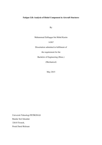
Fatigue Failure and Testing MethodsFigure 52.4Fatigue strength and tensile strength of common materialsDesign for fatigue failure2.4.1 Corrected fatigue strengthIt can be said that since fatigue properties of a material is easily influenced by manyfactors (size, surface, test method, environment and probability). The S-N curve obtained from laboratory tests has to be related to real-life design condition by modifyingit with some factors and least the laboratory results should not be used directly with noquestion.Laboratory endurance strength (Se’) of the materials obtain from S-N diagram (or thelikes) are therefore corrected for actual conditions by using correction factors like;Se Ka x Kb x Kc x Kd x Ke x Kf x Se’8(2)
Fatigue Failure and Testing MethodsWhere,Ka Surface Correction factorKb Size Correction factorKc Reliability Correction factorKd Temperature Correction factorKe Stress concentration Correction factorKf Miscellaneous Correction factorSe’ Endurance Strength of material specimen under laboratory conditionSe Endurance Strength of material specimen under actual running condition2.4.2 Selection of materials for fatigue resistanceIn many applications, the behavior of a component in service is influence by severalother factors besides the properties of the material used in its manufacture. This is particularly true for the cases where the component or structure is subjected to fatigue loading, the fatigue resistance can be greatly influenced by the service environment, surfacecondition of the part, method of fabrication and design details. In some cases, the role ofthe material in achieving satisfactory fatigue life is secondary to the above parameters,as long as the material is free from major flaws. Commonly used material type for design against fatigue is elaborated below with their basic characteristics.Steel and cast iron1. Steels are widely used as structural materials for fatigue application as they offer highfatigue strength and good process-ability at relatively low cost.2. The optimum steel structure for fatigue is tempered martensite, since it provides maximum homogeneity.3. Steel with high hardenability gives high strength with relatively mild quenching andhence, low residual stresses, which is desired in fatigue applications.4. Normalized structure, with their finer structure give better fatigue resistance thancoarse pearlite structure obtained by annealing.Nonferrous alloys1. Unlike ferrous alloys, the nonferrous alloys, with the exception of titanium, do notnormally have clear endurance limit.9
Fatigue Failure and Testing Methods2. Aluminum alloys usually combine corrosion resistance, light weight, and reasonablefatigue resistance3. Fine grained inclusion-free alloys are most suited for fatigue applications.Plastics1. The viscoelasticity of plastics makes their fatigue behavior more complex than that ofmetals.2. Fatigue behavior of plastics is affected by the type of loading, small changes in temperature and environment and method of fabrication3. Because of their low thermal conductivity, hysteretic heating can build up in plasticscausing them to fail in thermal fatigue or to function at reduces stiffness level.4. The amount of heat generated increases with increasing stress and test frequency.Composite materials1. The failure modes of reinforced materials in fatigue are complex and can be affectedby the fabrication process when difference in shrinkage between fibers and matrix induce internal stresses.2. However from practical experiences, some fiber reinforced plastics are known to perform better in fatigue than some metal3. The advantage of fiber-reinforced plastics is even more apparent when compared to aper weight basis.4. As with static strength, fiber orientation affects the fatigue strength of fiber reinforcedcomposite.5. In unidirectional composites, the fatigue strength is significantly lower in directionsother than the fiber orientation.6. Reinforcing with continuous unidirectional fibers is more effective than reinforcingwith short random fibers.10
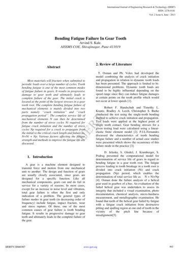
Fatigue Failure and Testing Methods3FATIGUE TESTING METHODSThe objective of a fatigue test is generally speaking to determine the fatigue life and/orthe danger point, i.e. the location of failure of a test-piece subjected to a prescribed sequence of stress amplitude.By simplifying and idealizing the test conditions, it would be possible to vary one or afew of the factors, which influence the fatigue life and to state their effects.Even if these conditions are fulfilled, there will always remain a number of unknownand uncontrollable factors which produce a large scatter in fatigue life even of test-piecewhich are considered to be identical.There are 2 basics for a classification of the different methods of fatigue testing.1. The sequence of stress amplitude.2. The nature of the test-piece.3.1Classification based on the sequence of stress amplitudes3.1.1 Constant-amplitude testThis is the simplest sequence of amplitude obtained by applying reversals of stress ofconstant-amplitude to the test-piece until failure occurs. Different specimens of the testseries may be subjected to different stress amplitude but for each individual item, theamplitude will never be varied.Figure 6Schematic Illustrating Cyclic Loading Parameters [Fuch & Stephens, 1980].11
Fatigue Failure and Testing MethodsThe following parameters are utilized to identify fluctuating stress cycles:Mean Stress,SmSm Smax Smin2(3)Stress Range, SrSr Smax Smin(4)Stress Amplitude, SaSa Smax Smin2(5)Stress Ratio, RR SminSmax(6)Depending upon the choice of stress levels, constant-amplitude tests may be classifiedinto three typesRoutine testIn routine test, the applied stresses are chosen in such a way that all specimens are expected to fail after a moderate number of cycles say 104 to 107, a few run-outs, althoughnot intended may be allowed.Short-life testThe stress levels are suited above the yield stress and some of the specimens are expected to fail statically at the application of the load.Long-life testIn this type of testing method, the stress levels are suited below or just above the fatigue limit and a fraction of the specimen does not fail after a pre-assigned number ofcycles about 106 to 107 cycles.3.1.2 Variable-amplitude testsMore complicated sequences of amplitude are required in order to simulate the stressesto which a specimen is subjected in actual service. A realistic simulation is very complicated.In order to discover laws in relation to the accumulation of fatigue damage in a specimen subjected to stress reversals of different amplitudes, the sequence of stress ampli-12
Fatigue Failure and Testing Methodstudes may be simplified. Independent of the pattern used, such tests is known as variable-amplitude tests.Figure 7Variable amplitude fatigue stress loadingVariable-amplitude tests can be further divided into:Cumulative damage testThese are tests where the objective is to investigate cumulative damage theory, in whichcase the sequences are frequently simplified.Service simulating testThese are tests which uses a more elaborate pattern (close to real service loading) forsimulating purpose.3.2Classification based on the nature of the test-pieceIt will suffice to divide the test-piece into two categories3.2.1 SpecimensThe term “specimen” is generally used in the sense of a test-piece of simple shape, frequently standardized, of small size and prepared carefully and with good surface finish.The purpose of the simplification is not to make it less expensive but more to reduce thevariability of the product and to keep different influential factors under control.Test-pieces of this type are generally intended for testing the material and for stating itsfatigue properties; they are also used extensively for research purposes.13
Fatigue Failure and Testing MethodsFigure 8Fatigue Test Specimens: (a) Rotating Bending, (b) Cantilever Flat Sheet (c)buttoned axial dog-bone, (d) threaded axial dog-bone, (e) torsion, (f) combined stress, (g) axial Cracked sheet, (h) part-through crack,(i) Compact tension and (j) three point bend specimen [Fuch & Stephens, 1980].Even if the simplified specimen may simulate many of the properties of actual machineparts, there are two factors pertaining to the component which are not represented in thespecimen i.e. design and fabrication. For this reason, it is indispensable to carry out actual tests with components in exactly the same condition as used in actual service.3.2.2 ComponentIt is used to signify any machine part, actual structure, machine and assembly includingelements simulating actual components.14
Fatigue Failure and Testing MethodsFigure 93-point bending test of a circuit board [2]Figure 10 Service testing of a whole car model3.3General Classification of Fatigue TestingBased on the three categories above, fatigue testing maybe divided base on the objectiveof the test, the three categories are:3.3.1 Material type testTest of the material type are useful for a comparison of the behavior of different materials subjected to repeated stresses, of the effects of various manufacturing processes, ofthe behavior of material in various environment, of various simple geometrical factorssuch as different sizes and shapes, of notches and different surface finishes.15
Fatigue Failure and Testing MethodsIt could also be used for elaborating the effect of surface treatment such as casehardening, decarburization, nitriding, shot-peening and plating on the fatigue propertiesof different materials.3.3.2 Structural type testThis type of test may be useful for a comparison of components made from differentmaterials, of different design and of structure fabricated by different procedures. Theymay also be used for revealing stress concentration and for developing better designs orbetter fabrication procedures.3.3.3 Actual service type testThey are tests usually used as reliability test or quality test, mainly for fault finding orverifying a new component in the machine or structure.Fatigue tests completely different in type from the above mentioned tests are thosewhich have as an objective a study of the initiation and propagation of fatigue cracks,this requires complex knowledge of fracture mechanics and microscopic view of material structure and it is beyond the scope of this thesis work.16
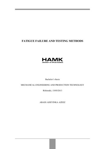
Fatigue Failure and Testing Methods4FATIGUE TESTING MACHINEA fatigue testing machine may be classified from different viewpoints such as purposeof the test, type of stressing, means of producing the load, operation characteristics, typeof load etc.The purpose of the investigation is the most important item for thee research and ofcourse, this is known when starting the investigation. Hence, it makes sense to base theclassification on the purpose of the test.4.1Classification of fatigue testing machineBase on the purpose of the test, fatigue testing machine can be divided into the following:1. General purpose fatigue testing machine2. Special purpose fatigue testing machine3. Equipment for testing parts and assembliesIn this work, the general purpose class will be expanded further as this is the widelyused type, most especially in academic environment.4.2General purpose testing machineThe general purpose testing machine can be further divided into two broad categories.They are the following:4.2.1 Classification based on type of stressing methodRotating bending testing machineThe type of S-N curve created by this machine is identified as a rotating-bending, stresscontrolled fatigue data curve. The rotating bending test machine is used to create an S-Ncurve by turning the motor at a constant revolution per minutes, or frequency. To createa failure on the specimen, a constant-stationary force is applied on the specimen, whichcreates a constant bending moment. A stationary moment applied to a rotating specimencauses the stress at any point on the outer surface of the specimen to go from zero to amaximum tension stress, back to zero and finally to a compressive stress. Thus, thestress state is one that is completely reversed in nature.17
Fatigue Failure and Testing MethodsFigure 11 Rotating Bending Testing Machine [Callister, 1994].Reciprocating bending test machineThe type of S-N curve produced is identified as a tension-compression, strain controlledfatigue data curve. This machine type is capable of zero mean cyclic stresses by positioning the specimen clamping vice with respect to the mean displacement position ofthe crank drive.Figure 12 Reciprocating Bending Testing Machine [Collins, 1981].Axial loading (push-pull) type fatigue testerIn this type the specimen is not exposed to bending but to pure axial (tensile or compressive) loading. Specimen is held at two ends and loaded cyclically between two extreme (maximum and minimum) values.18
Fatigue Failure and Testing MethodsFigure 13 Direct-Force Fatigue Testing Machine [Collins, 1981].The axial loading (push-pull) tester employing conversion attachments are also capableof bending and torsion fatigue testing when necessary, most commercial universal fatigue testing machines have this feature.Figure 14 Universal-tester .html]Other possible types, though not commonly used for simplified testing are:1. Torsion loading fatigue tester.2. Combined bending and torsion fatigue tester.3. Bi-axial and tri-axial loading fatigue tester.Classification based on source of stressing19
Fatigue Failure and Testing MethodsThe following classification of fatigue testing machine is based on the principle behindthe source of the test-force. Load produced by:1. Mechanical deflection2. Dead weight or constant spring force3. Centrifugal force4. Electromagnetic force5. Hydraulic force6. Pneumatic forceThe choice of load source depends on numerous factors such as the needed frequency,amount of forces required, available control system, cost, and how close the test is to besimplified to the actual working loading in service.4.3Components of a fatigue testing machineAll type of fatigue testing machine is composed of the following structural components:1. Load-producing mechanismThis generates the alternating load (displacement) to which in some cases a steady loadis added.2. Load-transmitting memberThis includes grips, guide fixtures, flexure joints etc. by which the load produced istransmitted in such a way as to produce the desired stress distribution within the specimen.3. Measuring devicesThis permit the setting of the nominal upper and lower load limits.4. Control devicesThis component controls the load throughout the test and sometimes automatically corrects changes in force or displacement arising during the test using feedback techniques.5. Counter and shut-off apparatusThis counts the number of stress reversals imposed on the specimen and stop the testingmachine after a given number of cycles, at complete fracture of the specimen or at somepre-assigned change in deformation or frequency.20
Fatigue Failure and Testing Methods6. FrameworkIt supports the various parts of the machine and if necessary is arranged to reduce thevibratory energy transmitted to the foundation.In conclusion, the purpose of a fatigue testing machine is to apply to the specimen analternating load producing a well-defined stress distribution. The distribution should bereproducible within narrow limits, a requirement which includes that the load should bereproduced with sufficient accuracy and it should be transmitted to the test-piece without undue scatters. Hence a careful and correct calibration and checking of the testingmachine is an indispensable condition for obtaining reliable results from any fatiguetesting machine.4.4The testing machine of HAMK University, mechatronic laboratoryThe testing machine (still under construction) is a universal testing machine which canbe used for tensile test, compressive test and fatigue testing. The hydraulic can produceforces up to 16KN and a frequency of maximum 10Hz.The machine is a servo-controlled hydraulic testing machine. It is controlled with phoenix programmable logic controller and can support wide ranges of load cell both foraxial force test and bending tests.A full description of the capability of the tester and its components specification including its user manual is available as a separate document.Figure 15 Dynamic testing mach
test the functionality of the dynamic testing machine once it is ready to run and also a planned fatigue test suitable for laboratory exercise in a material science or engineering design class was developed. Keywords Fatigue Failure, Fatigue Testing Methods and 4-point bending set-up. Pages 32 p. appendix