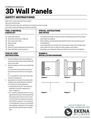
Transcription
INSTALLATION INSTRUCTIONS FOR*MSS9* & *CSS9*SINGLE-STAGE GAS FURNACE(Type FSP CATEGORY IV Director Non Direct Vent Air Furnace)These furnaces comply with requirements embodied in the American National Standard / National Standard of Canada ANSI Z21.47·CSA-2.3Gas Fired Central Furnaces.ONLY PERSONNEL THAT HAVE BEEN TRAINED TO INSTALL, ADJUST, SERVICE ORREPAIR (HEREINAFTER, “SERVICE”) THE EQUIPMENT SPECIFIED IN THIS MANUALSHOULD SERVICE THE EQUIPMENT. THE MANUFACTURER WILL NOT BE RESPONSIBLEFOR ANY INJURY OR PROPERTY DAMAGE ARISING FROM IMPROPER SERVICE ORSERVICE PROCEDURES. IF YOU SERVICE THIS UNIT, YOU ASSUME RESPONSIBILITYFOR ANY INJURY OR PROPERTY DAMAGE WHICH MAY RESULT. IN ADDITION, INJURISDICTIONS THAT REQUIRE ONE OR MORE LICENSES TO SERVICE THE EQUIPMENTSPECIFIED IN THIS MANUAL, ONLY LICENSED PERSONNEL SHOULD SERVICE THEEQUIPMENT. IMPROPER INSTALLATION, ADJUSTMENT, SERVICING OR REPAIR OFTHE EQUIPMENT SPECIFIED IN THIS MANUAL, OR ATTEMPTING TO INSTALL, ADJUST,SERVICE OR REPAIR THE EQUIPMENT SPECIFIED IN THIS MANUAL WITHOUT PROPERTRAINING MAY RESULT IN PRODUCT DAMAGE, PROPERTY DAMAGE, PERSONALINJURY OR DEATH .TABLE OF CONTENTSInstaller:Affix all manualsadjacent to the unit.As a professional installer you have an obligation to knowthe product better than the customer. This includes all safetyprecautions and related items.Prior to actual installation, thoroughly familiarize yourselfwith this Instruction Manual. Pay special attention to allsafety warnings. Often during installation or repair it ispossible to place yourself in a position which is morehazardous than when the unit is in operation.Remember, it is your responsibility to install the productsafely and to know it well enough to be able to instruct acustomer in its safe use.Safety is a matter of common sense.a matter of thinkingbefore acting. Most dealers have a list of specific goodsafety practices.follow them.The precautions listed in this Installation Manual are intendedas supplemental to existing practices. However, if there isa direct conflict between existing practices and the contentof this manual, the precautions listed here take precedence.RECOGNIZE THIS SYMBOLAS A SAFETY PRECAUTION.*NOTE:Please contact your distributor or our website forthe applicable Specification Sheet referred to in this manual.SAFETY CONSIDERATIONS . 3SHIPPING INSPECTION . 4ELECTROSTATIC DISCHARGE (ESD) PRECAUTIONS . 4TO THE INSTALLER . 5PRODUCT APPLICATION . 5LOCATION REQUIREMENTS & CONSIDERATIONS . 6CLEARANCES AND ACCESSIBILITY . 7EXISTING FURNACE REMOVAL . 8THERMOSTAT LOCATION . 8COMBUSTION & VENTILATION AIR REQUIREMENTS . 8INSTALLATION POSITIONS . 9HORIZONTAL APPLICATIONS & CONSIDERATIONS . 9FURNACE SUSPENSION . 9FRONT COVER PRESSURE SWITCH TUBE LOCATION . 9DRAIN TRAP AND LINES . 9LEVELING . 9ALTERNATE ELECTRICAL AND GAS LINE CONNECTIONS . 10DRAIN PAN . 10FREEZE PROTECTION . 10PROPANE GAS/HIGH ALTITUDE INSTALLATIONS . 10VENT/FLUE PIPE & COMBUSTION AIR PIPE . 10DUAL CERTIFICATION: NON-DIRECT/DIRECT VENT . 11MATERIALS AND JOINING METHODS . 11PROPER VENT/FLUE AND COMBUSTION AIR PIPING PRACTICES . 11TERMINATION LOCATIONS . 12CANADIAN VENT PIPE & COMBUSTION AIR PIPE REQUIREMENTS . 13STANDARD FURNACE CONNECTIONS . 13VENT/INTAKE TERMINATIONS FOR INSTALLATION OF MULTIPLE DIRECTVENT FURNACES . 18CONCENTRIC VENT TERMINATION . 18SIDE WALL VENT KIT . 18CONDENSATE DRAIN LINES & DRAIN TRAP . 18GENERAL DRAIN INFORMATION . 19FIELD SUPPLIED DRAIN . 19UPFLOW MODEL INSTALLED VERTICALLY . 195151 San Felipe Suite 500Houston, TX 77056www.goodmanmfg.com www.amana-hac.comIOG-2009L01/2018 2014-2018 Goodman Manufacturing Company, L.P.is a registered trademark of Maytag Corporation or its related companiesand is used under license. All rights reserved.
DRAIN EXITING RIGHT SIDE . 19DRAIN EXITING LEFT SIDE . 20UPFLOW MODEL INSTALLED HORIZONTALLY WITH RIGHT SIDE DOWN 20UPFLOW MODEL INSTALLED HORIZONTALLY WITH LEFT SIDE DOWN . 21UPFLOW MODEL INSTALLED HORIZONTALLY WITH LEFT SIDE DOWN ALTERNATE . 21COUNTERFLOW MODEL INSTALLED VERTICALLY . 22DRAIN EXITING LEFT SIDE (SEE FIGURE 26) . 22DRAIN EXITING RIGHT SIDE (SEE FIGURE 27) . 22COUNTERFLOW MODEL INSTALLED HORIZONTALLY WITH RIGHT SIDEDOWN (SEE FIGURE 28) . 23COUNTERFLOW MODEL INSTALLED HORIZONTALLYWITH LEFT SIDE DOWN . 23ELECTRICAL CONNECTIONS . 24WIRING HARNESS . 24115 VOLT LINE CONNECTIONS . 24JUNCTION BOX RELOCATION . 2524 VOLT THERMOSTAT WIRING . 25SINGLE-STAGE HEATING THERMOSTAT APPLICATION . 25FOSSIL FUEL APPLICATIONS . 25TWINNING . 26GAS SUPPLY AND PIPING . 26HIGH ALTITUDE DERATE . 27PROPANE GAS CONVERSION . 27GAS PIPING CONNECTIONS . 27PROPANE GAS TANKS AND PIPING . 29CIRCULATING AIR & FILTERS . 30DUCT WORK - AIR FLOW . 30CHECKING DUCT STATIC . 30BOTTOM RETURN AIR OPENING [UPFLOW MODELS] . 31FILTERS - READ THIS SECTION BEFORE INSTALLINGTHE RETURN AIR DUCT WORK . 31HORIZONTAL INSTALLATIONS . 32STARTUP PROCEDURE & ADJUSTMENT . 32DRAIN TRAP PRIMING . 32FURNACE OPERATION . 32GAS SUPPLY PRESSURE MEASUREMENT . 33GAS MANIFOLD PRESSURE MEASUREMENT AND ADJUSTMENT . 34GAS INPUT RATE MEASUREMENT (NATURAL GAS ONLY) . 34TEMPERATURE RISE . 34CIRCULATOR BLOWER SPEEDS . 35BLOWER HEAT OFF DELAY TIMINGS . 35NORMAL SEQUENCE OF OPERATION . 35POWER UP . 35HEATING MODE . 35COOLING MODE . 35FAN ONLY MODE . 36OPERATIONAL CHECKS . 36SAFETY CIRCUIT DESCRIPTION . 36INTEGRATED CONTROL MODULE . 36PRIMARY LIMIT . 36AUXILIARY LIMIT . 36ROLLOUT LIMIT . 36PRESSURE SWITCHES . 36FLAME SENSOR . 36TROUBLESHOOTING . 36ELECTROSTATIC DISCHARGE (ESD) PRECAUTIONS . 36DIAGNOSTIC CHART . 37RESETTING FROM LOCKOUT . 37MAINTENANCE . 37ANNUAL INSPECTION . 37FILTERS . 37BURNERS . 38INDUCED DRAFT AND CIRCULATOR BLOWERS . 38CONDENSATE TRAP AND DRAIN SYSTEM (QUALIFIED SERVICER ONLY) 38FLAME SENSOR (QUALIFIED SERVICER ONLY) . 38FLUE PASSAGES (QUALIFIED SERVICER ONLY) . 38BEFORE LEAVING AN INSTALLATION . 38REPAIR AND REPLACEMENT PARTS . 38TROUBLESHOOTING CHART . 39TROUBLESHOOTING CHART . 40AIRFLOW . 41-42*MSS92*** & *CSS92***A* . 41*MSS96*** & *CSS96***A* . 42WIRING DIAGRAM . 43*MSS92*** & *CSS92***A* . 43WIRING DIAGRAM . 44*MSS96*** & *CSS96***A*(WITH PCBBF138 CONTROL) . 44WIRING DIAGRAM . 45*MSS96*** & *CSS96***A*(WITH PCBBF140 CONTROL) . 45SPECIAL INSTRUCTIONS FOR PRODUCTS INSTALLEDIN THE STATE OF MASSACHUSETTS . 472
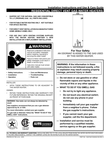
SAFETY CONSIDERATIONSWARNINGAdhere to the following warnings and cautions when installing, adjusting, altering, servicing, or operating the furnace.To ensure proper installation and operation, thoroughly readthis manual for specifics pertaining to the installation andapplication of this product.TO PREVENT PERSONAL INJURY OR DEATH DUE TO IMPROPERINSTALLATION , ADJUSTMENT, ALTERATION, SERVICE OR MAINTENANCE,REFER TO THIS MANUAL . FOR ADDITIONAL ASSISTANCE ORINFORMATION , CONSULT A QUALIFIED INSTALLER , SERVICER AGENCY ORTHE GAS SUPPLIER .This furnace is manufactured for use with natural gas. Itmay be field converted to operate on L.P. gas by using theappropriate L.P. conversion kit listed in the PROPANE GAS/HIGH ALTITUDE INSTALLATIONS section of this manualWARNINGIF THE INFORMATION IN THESE INSTRUCTIONS IS NOT FOLLOWEDEXACTLY, A FIRE OR EXPLOSION MAY RESULT CAUSING PROPERTYDAMAGE , PERSONAL INJURY OR LOSS OF LIFE.DO NOT STORE OR USE GASOLINE OR OTHER FLAMMABLE VAPORS ANDLIQUIDS IN THE VICINITY OF THIS OR ANY OTHER APPLIANCE .WHAT TO DO IF YOU SMELL GAS: D O NOT TRY TO LIGHT ANY APPLIANCE. D O NOT TOUCH ANY ELECTRICAL SWITCH; DO NOT USE ANY PHONEIN YOUR BUILDING . IMMEDIATELY CALL YOUR GAS SUPPLIER FROM A NEIGHBOR’ SPHONE. FOLLOW THE GAS SUPPLIER’S INSTRUCTIONS. IF YOU CANNOT REACH YOUR GAS SUPPLIER, CALL THE FIREDEPARTMENT.INSTALLATION AND SERVICE MUST BE PERFORMED BY A QUALIFIEDINSTALLER, SERVICE AGENCY OR THE GAS SUPPLIER.Install this furnace only in a location and position as specified in LOCATION REQUIREMENTS & CONSIDERATIONS section and INSTALLATION POSITIONS section of this manual.Provide adequate combustion and ventilation air to the furnace as specified in COMBUSTION & VENTILATION AIR REQUIREMENTS section of this manual.Combustion products must be discharged to the outdoors.Connect this furnace to an approved vent system only, asspecified in VENT/FLUE PIPE & COMBUSTION AIR PIPE section of this manual.Never test for gas leaks with an open flame. Use a commercially available soap solution made specifically for the detection of leaks to check all connections, as specified in GASSUPPLY AND PIPING section of this manual.WARNINGTHIS PRODUCT CONTAINS OR PRODUCES A CHEMICAL OR CHEMICALSWHICH MAY CAUSE SERIOUS ILLNESS OR DEATH AND WHICH AREKNOWN TO THE STATE OF C ALIFORNIA TO CAUSE CANCER , BIRTHDEFECTS OR OTHER REPRODUCTIVE HARM .Always install a furnace to operate within the furnace’s intended temperature-rise range with a duct system which hasexternal static pressure within the allowable range, as specified on the furnace rating plate and OPERATIONAL CHECKSsection of these instructions.WARNINGHEATING UNIT SHOULD NOT BE UTILIZED WITHOUT REASONABLE,ROUTINE, INSPECTION , MAINTENANCE AND SUPERVISION . IF THEWhen a furnace is installed so that supply ducts carry aircirculated by the furnace to areas outside the space containing the furnace, the return air shall also be handled by duct(s)sealed to the furnace casing and terminating outside thespace containing the furnace.BUILDING IN WHICH ANY SUCH DEVICE IS LOCATED WILL BE VACANT,CARE SHOULD BE TAKEN THAT SUCH DEVICE IS ROUTINELY INSPECTED,MAINTAINED AND MONITORED . IN THE EVENT THAT THE BUILDINGMAYBE EXPOSED TO FREEZING TEMPERATURES AND WILL BE VACANT ,A gas-fired furnace for installation in a residential garagemust be installed as specified in the LOCATION REQUIREMENTS AND CONSIDERATIONS section of this manual.ALL WATER -BEARING PIPES SHOULD BE DRAINED , THE BUILDING SHOULDBE PROPERLY WINTERIZED , AND THE WATER SOURCE CLOSED . IN THEEVENT THAT THE BUILDING MAY BE EXPOSED TO FREEZINGTEMPERATURES AND WILL BE VACANT , ANY HYDRONIC COIL UNITSThis furnace may be used as a construction site heater onlyif certain conditions are met. These conditions are listed inthe PRODUCT APPLICATION section of this manual.SHOULD BE DRAINED AS WELL AND , IN SUCH CASE , ALTERNATIVE HEATSOURCES SHOULD BE UTILIZED.CAUTIONWARNINGFROZEN AND BURST WATER PIPE HAZARDFAILURE TO PROTECT AGAINST THE RISK OF FREEZING MAY RESULT INPROPERTY DAMAGE.SPECIAL PRECAUTIONS MUST BE MADE IF INSTALLING FURNACE IN ANAREA WHICH MAY DROP BELOW FREEZING. THIS CAN CAUSE IMPROPEROPERATION OR DAMAGE TO EQUIPMENT. IF THE FURNACEENVIRONMENT HAS THE POTENTIAL OF FREEZING, THE DRAIN TRAP ANDDRAIN LINE MUST BE PROTECTED. THE USE OF ACCESSORY DRAIN TRAPHEATERS, ELECTRIC HEAT TAPE AND/OR RV ANTIFREEZE ISRECOMMENDED FOR THESE INSTALLATIONS.TO PREVENT POSSIBLE PROPERTY DAMAGE , PERSONAL INJURY ORDEATH DUE TO ELECTRICAL SHOCK , THE FURNACE MUST BE LOCATED TOPROTECT THE ELECTRICAL COMPONENTS FROM WATER .Drain trap must be primed at time of installation. Trap isinternally partitioned; add water to both inlet ports until water appears at both sides of the outlet opening. Failure toprime trap at time of installation may have a negative effect on combustion quality and pressure switch action.3
RISQUE D'EMPOISONNEMENT AU MONOXYDE DE CARBONEAdvertencia especial para la instalación de calentadores ó manejadorasde aire en áreas cerradas como estacionamientos ó cuartos de servicio.Las emisiones de monóxido de carbono pueden circular a travésdel aparato cuando se opera en cualquier modo.CO can cause serious illness including permanent braindamage or death.B10259-216Cette ventilation est nécessaire pour éviter le danger d'intoxicationau CO pouvant survenir si un appareil produisant du monoxydede carbone continue de fonctionner au sein de la zone confinée.El monóxido de carbono puede causar enfermedades severascomo daño cerebral permanente ó muerte.B10259-216Le monoxyde de carbone peut causer des maladies graves telles quedes dommages permanents au cerveau et meme la mort. B10259-216SHIPPING INSPECTIONAll units are securely packed in shipping containers tested according to International Safe Transit Association specifications.The carton must be checked upon arrival for external damage. Ifdamage is found, a request for inspection by carrier’s agentmust be made in writing immediately.WARNINGSHOULD OVERHEATING OCCUR OR THE GAS SUPPLY FAIL TO SHUT OFF,TURN OFF THE MANUAL GAS SHUTOFF VALVE EXTERNAL TO THEFURNACE BEFORE TURNING OFF THE ELECTRICAL SUPPLY.The furnace must be carefully inspected on arrival for damageand bolts or screws which may have come loose in transit. In theevent of damage the consignee should:1. Make a notation on delivery receipt of any visible damageto shipment or container.2. Notify carrier promptly and request an inspection.3. With concealed damage, carrier must be notified as soonas possible - preferably within five days.4. File the claim with the following support documents withina nine month statute of limitations. Original or certified copy of the Bill of Lading, orindemnity bond. Original paid freight bill or indemnity in lieu thereof. Original or certified copy of the invoice, showing tradeand other discounts or reductions. Copy of the inspection report issued by carrier’srepresentative at the time damage is reported to carrier.WARNINGPOSSIBLE PROPERTY DAMAGE , PERSONAL INJURY OR DEATH DUE TOFIRE, EXPLOSION , SMOKE, SOOT, CONDENSATION , ELECTRICAL SHOCKOR CARBON MONOXIDE MAY RESULT FROM IMPROPER INSTALLATION,REPAIR OPERATION, OR MAINTENANCE OF THIS PRODUCT.electrostatic potential, these steps will help avoid exposingthe integrated control module to electrostatic discharge. Thisprocedure is applicable to both installed and non-installed(ungrounded) furnaces.1. Disconnect all power to the furnace. Do not touch theintegrated control module or any wire connected to thecontrol prior to discharging your body’s electrostaticcharge to ground.2. Firmly touch a clean, unpainted, metal surface of thefurnaces near the control. Any tools held in a person’shand during grounding will be discharged.3. Service integrated control module or connecting wiringfollowing the discharge process in step 2. Use caution notto recharge your body with static electricity; (i.e., do notmove or shuffle your feet, do not touch ungroundedobjects, etc.). If you come in contact with an ungroundedobject, repeat step 2 before touching control or wires.4. Discharge your body to ground before removing a newcontrol from its container. Follow steps 1 through 3 ifinstalling the control on a furnace. Return any old or newcontrols to their containers before touching any ungroundedobject.The carrier is responsible for making prompt inspection of damage and for a thorough investigation of each claim. The distributor or manufacturer will not accept claims from dealers for transportation damage.ELECTROSTATIC DISCHARGE (ESD) PRECAUTIONSNOTE: Discharge your body’s static electricity before touchingunit. An electrostatic discharge can adversely affect electricalcomponents.Use the following precautions during furnace installation and servicing to protect the integrated control module from damage. Byputting the furnace, the control, and the person at the same4
TO THE INSTALLERIn the U.S.A., this furnace may be used as a construction siteheater ONLY if all of the following conditions are met: The vent system is permanently installed per theseinstallation instructions. A room thermostat is used to control the furnace. Fixedjumpers that provide continuous heating CANNOT beused and can cause long term equipment damage. Bimetal thermostats, or any thermostat affected byvibration, must not be used during construction. Return air ducts are provided and sealed to the furnace. A return air temperature range between 60ºF (16ºC)and 80ºF (27ºC) is maintained. Air filters are installed in the system and replaced dailyduring construction and upon completion of construction. The input rate and temperature rise are set per thefurnace rating plate. The furnace must be installed as a two pipe system,using 100% outside air for combustion duringconstruction. The furnace heat exchanger, components, ductsystem, air filters and evaporator coils arethoroughly cleaned following final construction cleanup by a qualified person. All furnace operating conditions (including ignition, inputrate, temperature rise and venting) are verifiedaccording to these installation instructions. Furnace doors must be in place on the furnace whilethe furnace is operating in any mode. Damage or repairs due to failure to comply withthese requirements are not covered under thewarranty.Before installing this unit, please read this manual thoroughly tofamiliarize yourself with specific items which must be adheredto, including but not limited to: unit maximum external staticpressure, gas pressures, BTU input rating, proper electrical connections, circulating air temperature rise, minimum or maximum CFM, and motor speed connections.PRODUCT APPLICATIONThis furnace is primarily designed for residential home-heatingapplications. It is NOT designed or certified for use in mobilehomes, trailers or recreational vehicles. Neither is it designedor certified for outdoor applications. The furnace must be installed indoors (i.e., attic space, crawl space, or garage areaprovided the garage area is enclosed with an operating door).This furnace can be used in the following non-industrial commercial applications:Schools, Office buildings, Churches, Retail stores, Nursinghomes, Hotels/motels, Common or office areasIn such applications, the furnace must be installed with the following stipulations: It must be installed per the installation instructionsprovided and per local and national codes. It must be installed indoors in a building constructed onsite. It must be part of a ducted system and not used in afree air delivery application. It must not be used as a “make-up” air unit. It must be installed as a two-pipe systems forcombustion air. All other warranty exclusions and restrictions apply Thisfurnace is an ETL dual-certified appliance and isappropriate for use with natural or propane gas (NOTE:If using propane, a propane conversion kit is required).NOTE: The Commonwealth of Massachusetts requires that thefollowing additional requirements must also be met: Gas furnaces must be installed by a licensed plumber orgas fitter. A T-handle gas cock must be used. If the unit is to be installed in an attic, the passagewayto and the service area around the unit must haveflooring.Dual certification means that the combustion air inlet pipe isoptional and the furnace can be vented as a:Non-direct vent (single pipe) central forced air furnacein which combustion air is taken from the installationarea or from air ducted from the outside or,Direct vent (dual pipe) central forced air furnace inwhich all combustion air supplied directly to the furnaceburners through a special air intake system outlined inthese instructions.To ensure proper furnace operation, install, operate and maintain the furnace in accordance with these installation andoperation instructions, all local building codes and ordinances.In their absence, follow the latest edition of the National FuelGas Code (NFPA 54/ANSI Z223.1), and/or CAN/CSA B149.1-15Installation Codes, local plumbing or waste water codes, and otherapplicable codes.Gas furnaces manufactured on or after May 1, 2017 are notpermitted to be used in Canada for heating of buildings orstructures under construction.WARNINGTO PREVENT PROPERTY DAMAGE , PERSONAL INJURY OR DEATH DUE TOFIRE, DO NOT INSTALL THIS FURNACE IN A MOBILE HOME, TRAILER , ORRECREATIONAL VEHICLE.5
A copy of the National Fuel Gas Code (NFPA 54/ANSI Z223.1)can be obtained from any of the following: American National Standards Institute23 West 43rd Street, 4th FloorNew York, NY 10036National Fire Protection Association1 Batterymarch ParkQuincy, MA 02169-7471 CSA International8501 East Pleasant ValleyIndependence, OH 441311 The rated heating capacity of the furnace should be greater thanor equal to the total heat loss of the area to be heated. The totalheat loss should be calculated by an approved method or in accordance with “ASHRAE Guide” or “Manual J-Load Calculations”published by the Air Conditioning Contractors of America. A copy of the CAN/CSA B149.1-15 Installation Codes can alsobe obtained from: CSA International178 Rexdale BoulevardEtobicoke, Ontario, Canada M9W 1R3LOCATION REQUIREMENTS & CONSIDERATIONSFollow the instructions listed below and the guidelines providedin the Combustion and Ventilation Air Requirements section whenselecting a furnace location. WARNINGTO PREVENT POSSIBLE EQUIPMENT DAMAGE , PROPERTY DAMAGE,PERSONAL INJURY OR DEATH , THE FOLLOWING BULLET POINTS MUST BEOBSERVED WHEN INSTALLING THIS UNIT.WARNINGPOSSIBLE PROPERTY DAMAGE , PERSONAL INJURY OR DEATH DUE TOFIRE, EXPLOSION , SMOKE, SOOT, CONDENSATION , ELECTRICAL SHOCKOR CARBON MONOXIDE MAY RESULT FROM IMPROPER INSTALLATION,REPAIR OPERATION, OR MAINTENANCE OF THIS PRODUCT. Centrally locate the furnace with respect to theproposed or existing air distribution system.Ensure the temperature of the return air entering thefurnace is between 55 F and 100 F when the furnace isheating.Provide provisions for venting combustion productsoutdoors through a proper venting system. Specialconsideration should be given to vent/flue pipe routingand combustion air intake pipe when applicable. Referto Vent/Flue Pipe and Combustion Air Pipe -TerminationLocations for appropriate termination locations and todetermine if the piping system from furnace totermination can be accomplished within the guidelinesgiven. NOTE: The length of flue and/or combustion 6air piping can be a limiting factor in the location of thefurnace.Locate the furnace so condensate flows downwards tothe drain. Do not locate the furnace or its condensatedrainage system in any area subject to below freezingtemperatures without proper freeze protection. Referto Condensate Drain Lines and Trap for further details.Ensure adequate combustion air is available for thefurnace. Improper or insufficient combustion air canexpose building occupants to gas combustion productsthat could include carbon monoxide. Refer toCombustion and Ventilation Air Requirements.Set the furnace on a level floor to enable propercondensate drainage. If the floor becomes wet or dampat times, place the furnace above the floor on a concretebase sized approximately 1-1/2" larger than the baseof the furnace. Refer to the Horizontal Applicationsand Considerations for leveling of horizontal furnaces.Ensure upflow or horizontal furnaces are not installeddirectly on carpeting, or any other combustible material.The only combustible material allowed is wood.A special accessory subbase must be used for uprightcounterflow unit installations over any combustiblematerial (including wood). Refer to subbase instructionsfor installation details. (NOTE: A subbase will not berequired if an air conditioning coil is located beneaththe furnace between the supply air opening and thecombustible floor.Exposure to contaminated combustion air will result insafety and performance-related problems. Do not installthe furnace where the combustion air is exposed to thefollowing substances:permanent wave solutionschlorinated waxes or cleanerschlorine-basedcarbon tetrachloridewater softening chemicalsswimming pool chemicalsdeicing salts or chemicalshalogen type refrigerantsprinting inkscleaning solutions (such as perchloroethylene)paint removersvarnisheshydrochloric acidcements and gluesantistatic fabric softeners for clothes dryersmasonry acid washing materialsSeal off a non-direct vent furnace if it is installednear an area frequently contaminated by any of theabove substances. This protects the non-direct ventfurnace from airborne contaminants. To ensure thatthe enclosed non-direct vent furnace has an adequatesupply of combustion air, vent from a nearbyuncontaminated room or from outdoors. Refer tothe Combustion and Ventilation Air Requirementsfor details.
If the furnace is used in connection with a cooling coilunit, install the furnace upstream or in parallel with thecooling coil unit. Premature heat exchanger failure willresult if the cooling unit is placed ahead of the furnace.For vertical (upflow or downflow) applications, theminimum cooling coil width shall not be less thanfurnace width minus 1”. Additionally, a coil installedabove an upflow furnace or under a counterflowfurnace may be the same width as the furnace ormay be one size larger than the furnace. Example:a “C” width coil may be installed with a “B” widthfurnace.For upflow applications, the front of the coil andfurnace must face the same direction.If the furnace is installed in a residential garage,position the furnace so that the burners and ignitionsource are located not less than 18 inches (457 mm)above the floor. Protect the furnace from physicaldamage by vehicles.If the furnace is installed horizontally, ensure the accessdoors are not on the “up/top” or “down/bottom” sideof the furnace.Do not connect this furnace to a chimney flue thatserves a separate appliance designed to burn solidfuel.On Counterflow Installations, the air conditioningcoil must be downstream on the supply (positive)side of the furnace heat exchanger.Counterflow Installation over a noncombustiblefloor. Before setting the furnace over the plenumopening, ensure the surface around the opening issmooth and level. A tight seal should be madebetween the furnace base and floor by using asilicone rubber caulking compound or cement grout.Counterflow Installation over a combustible floor. Ifinstallation over a combustible floor becomes necessary,use an accessory subbase (see Specification Sheetapplicable for your model for details.) A special accessorysubbase must be used for upright counterflow unitinstallations over any combustible material includingwood. Refer to subbase instructions for installationdetails. Follow the instructions with the subbase forproper installation. Do not install the furnace directlyon carpeting, tile, or other combustible material otherthan wood flooring. (NOTE: The subbase will not berequired if an air conditioning coil is installed betweenthe supply air opening on the furnace and the floor.)*M SS[92 & 96]
ing, adjusting, altering, servicing, or operating the furnace. To ensure proper installation and operation, thoroughly read this manual for specifics pertaining to the installation and application of this product. This furnace is manufactured for use with natural gas. It may be field converted to operate on L.P. gas by using the