Transcription
cesTechnical InformationEngyCal RS33Steam calculatorFor recording and billing the steam mass andenergy flow in applications with saturated steam orsuperheated steamTransparent energy consumption helps you save onenergy costsApplication Recording and billing energy quantities in steam applicationsTypical applications are in: the food industry the chemical industry the pharmaceutical industry power plants building services and plant engineering and construction.Your benefits Compensation of differential pressure flow measurement Fast commissioning thanks to easy operation in selectable language and plain-textdisplay Remote readout via Ethernet and fieldbuses Calculation according to international steam tables Integrated data logging Tariff counter for requirements-specific metering Standard models are suitable for connecting and supplying all common flow transmitters, temperature sensors and pressure sensors Deficit counter for transparency in case of error or alarm Detailed data logging of current and counter values and of error messages, off-limitconditions and changes to operating parameters Industry-compliant compact housing for field or wall mounting, panel mounting ortop-hat rail mounting Electronic alignment of the temperature sensor with the arithmetic unit (sensortransmitter matching) enables high-accuracy temperature measurement
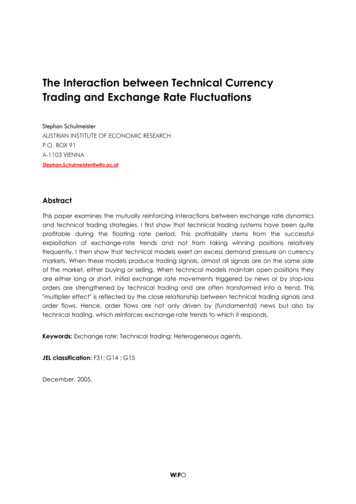
EngyCal RS33Function and system designMeasuring principleThe EngyCal RS33 steam calculator is used for recording the steam mass and energy flow in systemswith saturated steam or superheated steam. The calculation is based on the measured process valuesvolume flow, temperature and/or pressure. Depending on the installation position of the measuringdevices the heat quantity can be determined using different calculation methods. This can be performed using standard heat quantity calculations, or using steam delta heat measurement. If steamdelta heat measurement is used, attention must be paid to the installation position of the measuringdevices.The measured and calculated values can be output via ethernet, fieldbuses or as an analog signal. Themeters are easy to install and read. Thanks to its verified long-term stability and high-precision measurements, the device helps optimize processes and control costs in the process. Comprehensive dataanalysis options in the Field Data Manager software MS20 (see accessories) identify potential areasfor cost reduction.Measuring systemDevelopment of different applications such as heat quantity or delta heat with the steam calculatorDelta heat/pDelta heat/TA0022321FunctionsHeat quantity or delta heat/p TA0022322A0022323Energy calculationEngyCal RS33 uses the IAPWS IF97 standard to calculate the mass flow and energy flow of steam.Here, the density and enthalpy of steam is calculated from the input variables pressure and temperature.Calculated values: Power Volume Mass Density Enthalpy DP flow compensationCounters: Volume Mass Energy Deficit Optional:Tariff1, tariff2Temperature-sensor matching in the computerThe temperature sensor is adapted internally in the EngyCal RS33 by storing the sensor characteristiccurves via Callendar-van-Dusen coefficients. The Callendar-van-Dusen coefficients are determined bycalibrating the temperature sensor.2Endress Hauser
EngyCal RS33Compensation of differential pressure flow measurementThe flow calculation according to the differential pressure method is a special form of flow measurement. Volume or mass flow values measured according to the DP method require a specific correction.The iterative solution of the calculation equations listed there allow the best possible accuracy (ca. 0.6– 1 %) to be attained for DP flow measurements.Compensation of flow measurement for throttle methods (orifice plate, nozzle).The measurement (orifice plate, nozzle, Venturi pipe) is carried out according to ISO5167. Flow measurements according to the dynamic pressure method are determined according to the relationshipbetween the differential pressure and flow.Data logging and logbookEvent logbook:The EngyCal RS33 steam calculator has a logbook for measured values and a logbook for events.In the event logbook, all parameter changes, off-limit conditions, alarms and other events are documented with timestamp such that they are tamper-proof. At minimum, the last 1600 events are storedin non-volatile memory.The data logging allows process values and calculated values, as well as counters, to be stored in freelydefinable intervals. Predefined analyses (Day, Month, Year, Billing dates) support the transparency ofthe process and ensure a quick overview of all consumption values.All entries into the event logbook and the logged data can be read out automatically via the visualization software (Field Data Manager Software) and backed up in an SQL database so that it is tamperproof.For fast and easy-to-understand analysis in case of service, an internal diagnostic memory withoccurred error messages is also available.AnalysisNo. of analysesInterval (1min)Approx. 700Day260 daysMonth/year/billing date17 yearsEventsAt least 1600 (depending on the length of the message text)Wet steam alarmIf steam condenses, reliable and accurate calculation of the energy quantity is no longer guaranteed.The wet steam alarm indicates the condensation of steam. The aggregate state can be determined onthe basis of pressure and temperature. This is required in order to trigger the wet steam alarm.Limit value monitoringEngyCal RS33 has 3 limits that can be assigned as desired to the following measured and calculatedvalues:Volume flow, steam temperature, pressure, mass flow, power (heat flow), density, enthalpy, operatingvolume, heat and tariff 1, tariff 2In case of violation of the defined limits, an entry is made into the event logbook. In addition, relayscan be switched and the off-limit condition can be indicated on the display. Limits are also available viathe integrated web server.Fault mode / deficit counterEngyCal RS33 has a definable fault mode (no further calculation or calculation with error value).For the case of further calculation with an error value, the total calculated energy during the error condition (e.g. cable open circuit or wet steam alarm) is counted on a deficit counter.In this case, the output continues to supply the calculated energy value. If values are communicated viabuses, these are given the value "invalid". Optionally, an alarm relay can be switched.Endress Hauser3
EngyCal RS33Tariff counters (optional)The tariff counters enable analysis and recording of the energy on an additional counter.Two types of tariff counter are available: A defined tariff can be activated by an event or via the digitalinputs. If the defined event occurs, the calculated energy is counted at this tariff.Tariff counters enable, for example, invoicing on specific billing dates (due date invoicing), requirements-based billing (daytime/nighttime tariff) and analysis of counters when reaching set points, e.g.power-dependent.Various tariff models are available for selection in the device, e.g. Energy; Power; Mass flow; Wetsteam; Time.The standard counters continue running at the same time, e.g. they are not affected by the activationof the tariff counters.Real time clock (RTC)The device has a real time clock that can be synchronized via a free digital input or using the Field DataManager software MS20.The real time clock continues running even in case of a power failure, the device documents power onand off; the clock switches automatically or (optionally) manually from daylight saving to standardtime.DisplayTo display measured values, counters and calculated values, 6 groups are available. Each group can beassigned up to 3 values or meter readings as desired.Analyzing the stored data - Field Data Management software MS20The Field Data Manager Software allows the stored measured values, alarms and events, and thedevice configuration to be read out from the device (automatically) so that they are tamper-proof andstored securely in an SQL database. The software offers centralized data management with a variety ofvisualization functions. Using an integrated system service, analyses and reports can be created,printed and stored fully automatically. Security is provided by the FDA-compliant audit trail of the software and the extensive user management. Simultaneous access and analysis of data from variousworkstations or users is supported (client-server architecture).4Endress Hauser
EngyCal RS33InputCurrent/pulse inputThis input can be used either as a current input for 0/4 to 20 mA signals or as a pulse input or frequency input.The input is galvanically isolated (500 V testing voltage towards all other inputs and outputs).Cycle timeThe cycle time is 250 ms or 500 ms respectively when using one or two RTD inputs.Reaction timeIn the case of analog signals, the reaction time is the time between the change at the input and thetime when the output signal is equivalent to 90% of the full scale value. The reaction time is lengthenedby 250 ms if an RTD with 3-wire measurement is connected.InputOutputReaction time [ms]CurrentCurrent 600CurrentRelay/digital output 600RTDCurrent/ relay/digital output 600Cable open circuit detectionCurrent/ relay/digital output 600Cable open circuit detection, RTDCurrent/ relay/digital output 1100Pulse inputPulse output 600Current inputEndress HauserMeasuring range:0/4 to 20 mA 10 % over rangeAccuracy:0.1 % of full scale valueTemperature drift:0.01 %/K (0.0056 %/ F) of the full scale valueLoading capacity:Max. 50 mA, max. 2.5 VInput impedance (load):50 ΩHART signalsNot affectedA/D converter resolution:20 bit5
EngyCal RS33Pulse/frequency inputThe pulse/frequency input can be configured for different frequency ranges: Pulses and frequencies up to 12.5 kHz Pulses and frequencies up to 25 Hz (filters out bounce contacts, max. bounce time: 5 ms)Minimum pulse width:Range up to 12.5 kHzRange up to 25 Hz40 μs20 msMaximum permissible contact bounce time:Range up to 25 Hz5 msPulse input for active voltage pulses and contact sensors as per EN 1434-2, Class IB and IC:Non-conductive stateConductive state 1V 2VNo-load supply voltage:3 to 6 VCurrent limiting resistance in the power supply(pull-up at input):50 kΩ to 2 MΩMaximum permissible input voltage:30 V (for active voltage pulses)Pulse input for contact sensors as per EN 1434-2, Class ID and IE:Low-levelHigh-level 1.2 mA 2.1 mANo-load supply voltage:7 to 9 VCurrent limiting resistance in the power supply(pull-up at input):562 Ωto 1 kΩNot suitable for active input voltages.Current/pulse input:Low-levelHigh-level 8 mA 13 mALoading capacity:Max. 50 mA, max. 2.5 VInput impedance (load):50 ΩAccuracy during frequency measurement:Basic accuracy:0.01 % of measured valueTemperature drift:0.01 % of measured value over entire temperature rangePulse output of the flowsensorRS33 settingMechanical contactPulse ID/IE up to25 HzElectrical connectionRemark"Pulse IB/IC U" up to 25 Hz canalso be used. The current throughthe contact is lower then (approx.0.05 mA instead of 9 mA).Advantage: less load;disadvantage: lower interferenceresistance.A0015354A SensorB RS336Endress Hauser
EngyCal RS33Pulse output of the flowsensorRS33 settingOpen Collector (NPN)Pulse ID/IE up to 25 Hzor up to 12.5 kHzElectrical connectionRemark"Pulse IB/IC U" can also be used.The current through the contact islower then (approx. 0.05 mAinstead of 9 mA). Advantage: lessload; disadvantage: lowerinterference resistance.A0015355A SensorB RS33Active voltageThe switching threshold isbetween 1 V and 2 VPulse IB/IC UA0015356A SensorB RS33Active currentThe switching threshold isbetween 8 mA and 13 mAPulse IA0015357A SensorB RS33Namur sensor (as perEN60947-5-6)No monitoring for short circuit iscarried out.Pulse ID/IE up to 25 Hzor up to 12.5 kHzA0015359A SensorB RS33Endress Hauser7
EngyCal RS332 x current/RTD inputThese inputs can be used either as current inputs (0/4 to 20 mA) or as resistance temperature detector(RTD) inputs. Here, one input is provided for the temperature signal, the other for the pressure signal.The two inputs are galvanically connected but galvanically isolated from the other inputs and outputs(testing voltage: 500 V).Current inputMeasuring range:0/4 to 20 mA 10 % over rangeAccuracy:0.1 % of full scale valueTemperature drift:0.01 %/K (0.0056 %/ F) of the full scale valueLoading capacity:Max. 50 mA, max. 2.5 VInput impedance (load):50 ΩA/D converter resolution:24 bitHART signals are not affected.RTD inputPt100, Pt500 and Pt1000 resistance temperature detectors can be connected to this input.Measuring ranges:Digital inputsPt100 exact:Pt100 wide:Pt500:Pt1000:-200 to 300 C (-328 to 572 F)-200 to 600 C (-328 to 1112 F)-200 to 300 C (-328 to 572 F)-200 to 300 C (-328 to 572 F)Connection method:2-, 3- or 4-wire connectionAccuracy:4-wire:0.06% of measuring range3-wire:0.06% of the measuring range 0.8 K (1.44 F))Temperature drift:0.01 %/K (0.0056 %/ F) of the measuring rangeCharacteristic curves:DIN EN 60751:2008 IPTS-90Max. cable resistance:40 ΩCable open circuit detection:Outside the measuring rangeTwo digital inputs are available for switching the following functions.Digital input 1Digital input 2Activate tariff counter 1Time synchronizationLock device (Block set up)Activate tariff counter 2Time synchronizationLock device (Block set up)Input level:To IEC 61131-2 type 3:Logical "0" (corresponds to -3 to 5 V), activation with logical "1" (corresponds to 11 to 30 V)Input current:Max. 3.2 mAInput voltage:Max. 30 V (steady-state, without destroying the input)8Endress Hauser
EngyCal RS33OutputCurrent/pulse output(option)This output can be used either as a 0/4 to 20 mA current output or as a voltage pulse output. The output is galvanically isolated (500 V testing voltage towards all other inputs and outputs).Current outputOutput range:0/4 to 20 mA 10 % over rangeLoad:0 to 600 Ω (as per IEC 61131-2)Accuracy:0.1 % of full scale valueTemperature drift:0.01 %/K (0.0056 %/ F) of the full scale valueInductive load:Max. 10 mHCapacitance load:Max. 10 μFRipple:Max. 12 mVpp on 600 Ω for frequencies 50 kHzD/A converter resolution:14 bitPulse outputFrequency:Max. 12.5 kHzPulse width:Min. 40 μsVoltage level:Low: 0 to 2 VHigh: 15 to 20 VMaximum output current:22 mAShort-circuit proof2 x relay output2 x digital output, open collector (option)Endress HauserThe relays are designed as NO contacts. The output is galvanically isolated (1500 V testing voltagetowards all other inputs and outputs).Max. relay switching capacity:AC: 250 V, 3 ADC: 30 V, 3 AMinimum contact load:10 V, 1 mAMin. switching cycles: 105The two digital inputs are galvanically isolated from one another and from all the other inputs and outputs (testing voltage: 500 V). The digital outputs can be used as status or pulse outputs.Frequency:Max. 1 kHzPulse width:Min. 500 μsCurrent:Max. 120 mAVoltage:Max. 30 VVoltage drop:Max. 2 V in conductive stateMaximum load resistance:10 kΩFor higher values, the switching edges are flattened.9
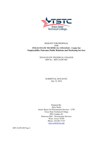
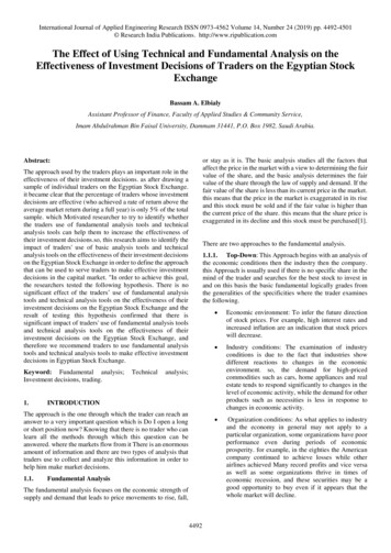
EngyCal RS33Auxiliary voltage output(transmitter power supply)The auxiliary voltage output can be used to power the transmitter or control the digital inputs. The auxiliary voltage is short-circuit proof and galvanically isolated (500 V testing voltage towards all otherinputs and outputs).Output voltage:24 V DC 15% (not stabilized)Output current:Max. 70 mA HART signals are not affected.Terminal assignmentElectrical connection (circuitdiagrams)A0022341Terminal assignment of the EngyCal RS33.Supply voltage Low-voltage power unit: 100 to 230 V AC (-15% / 10%) 50/60 Hz Extra-low voltage power unit:24 V DC (-50% / 75%)24 V AC ( 50%) 50/60 HzAn overload protection unit (rated current 10 A) is required for the power cable.Power consumption1015 VAEndress Hauser
EngyCal RS33Communication interfacesA USB interface (with CDI protocol), and optionally Ethernet, are used to configure the device and readout the values. ModBus and M-Bus are optionally available as communication interfaces.None of the interfaces has a modifying effect on the device in accordance with PTB Requirement PTBA 50.1.USB deviceEthernet TCP/IPConnection:Type B socketSpecification:USB 2.0Speed:Full speed (max. 12 MBit/sec)Max. cable length:3 m (9.8 ft.)The Ethernet interface is optional, and cannot be combined with other optional interfaces. It is galvanically isolated (testing voltage: 500 V). A standard patch cable (e.g. CAT5E) can be used to connect theEthernet interface. A special cable gland is available for this purpose which allows users to guide preterminated cables through the housing. Via the Ethernet interface, the device can be connected tooffice equipment using a hub or a switch.Standard:10/100 Base-T/TX (IEEE 802.3)Socket:RJ-45Max. cable length:100 m (328 ft.)Web serverWhen the device is connected via Ethernet, the display values can also be read out via the Internetusing a web server.Data can be read out via the web server in HTML or XML format.RS485Connection3-pin plug-in terminalTransmission protocolRTUTransmission rate2400/4800/9600/19200/38400ParityChoose from None, Even, OddModbus TCPThe Modbus TCP interface is optional, and cannot be ordered with other optional interfaces. It is usedto connect the device to higher-order systems to transmit all measured values and process values. TheModbus TCP interface is physically identical to the Ethernet interface.Modbus RTUThe Modbus RTU (RS-485) interface is optional, and cannot be ordered with other optional interfaces.It is galvanically isolated (testing voltage: 500 V) and used to connect the device to higher-order systems to transmit all measured values and process values. It is connected via a 3-pin plug-in terminal.M-BusThe M-Bus (Meter Bus) interface is optional, and cannot be ordered with other optional interfaces. Itis galvanically isolated (testing voltage: 500 V) and used to connect the device to higher-order systemsto transmit all measured values and process values. It is connected via a 3-pin plug-in terminal.Endress Hauser11
EngyCal RS33Performance characteristicsReference operating conditionsArithmetic unit Power supply 230 V AC 10%; 50 Hz 0.5 HzWarm-up time 2 hAmbient temperature 25 C 5 K (77 9 F)Humidity 39% 10% RHMediumSteamVariableRangeTemperature measuring range0 to 800 C (32 to 1472 F)Pressure measuring range0 to 1000 bar (0 to 14500 PSI)Measurement and calculation interval500 msCalculation standard IAPWS IF97Typical accuracy in steam mass and energy measurement of a complete steam measuring point:approx. 1.5 % (e.g. Cerabar S, TR 10, Prowirl 72, EngyCal RS33)InstallationInstallation instructionsMounting locationWall/pipe mounting, panel or top-hat rail as per IEC 607151)OrientationThe orientation is only determined by the legibility of the display.1)12According to UL approval panel or surface mountable only.Endress Hauser
EngyCal RS33EnvironmentAmbient temperature range-20 to 60 C (-4 to 140 F)Storage temperature-30 to 70 C (-22 to 158 F)Climate classAs per IEC 60 654-1 Class B2, as per EN 1434 ambient class CHumidityMaximum relative humidity 80 % for temperatures up to 31 C (87.8 F), decreasing linearly to 50 %relative humidity at 40 C (104 F).Electr. safetyAs per IEC 61010-1, UL61010-1 and CAN C22.2 No 1010-1. Protection class II Overvoltage category II Pollution degree 2 Overload protection 10 A Operating altitude: up to 2000 m (6560 ft) above MSLDegree of protection Panel mounting: IP65 front panel, IP20 rear panel (not evaluated by UL) Top-hat rail: IP20 Field housing: IP66, NEMA4x (for cable gland with double seal insert: IP65) (not evaluated by UL)Electromagnetic compatibilityAs per EN 1434-4, EN 61326 and Namur NE21Endress Hauser13
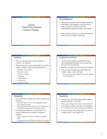
EngyCal RS33Mechanical constructionDesign, dimensionsA0013438Dimensions in mm (in)WeightApprox. 700 g (1.5 lbs)MaterialHousing: fiber-glass reinforced plastic, Valox 553TerminalsSpring terminals, 2.5 mm2 (14 AWG); auxiliary voltage with plug-in screw terminal (AWG30-12;torque 0.5-0.6 Nm).14Endress Hauser
EngyCal RS33Human interfaceDisplay elements Display:160 x 80 dot matrix LCD with white background, color switches to red in an alarm condition, activedisplay area 70 x 34 mm LED status display:Operation: 1 x greenFault indication: 1 x redA0013444Display and operating elements12345LED green, "Operation"LED red, "Fault indicator"USB connection for configurationOperating keys: -, , E160x80 DOT matrix displayLocal operation3 keys, "-", " ", "E".Configuration interfaceUSB interface, front-panel, optional Ethernet interface: configuration via PC with PC operating software.Data loggingReal time clock Drift: 15 min per year Power reserve: 1 weekSoftwareEndress Hauser Field Data Manager software MS20: Visualization software and database for analyzing and evaluating the measuring data and calculated values, as well as tamper-proof data storage FieldCare Device Setup: The device can be programmed using the FieldCare PC software. FieldCareDevice Setup is included in the scope of supply of the Commubox FXA291 or RXU10-G1 (see ‘Accessories’) or can be downloaded at no charge from www.products.endress.com/fieldcare.15
EngyCal RS33Certificates and approvalsCE markThe measuring system meets the legal requirements of the EU directives. Endress Hauser confirmssuccessful testing of the device by affixing to it the CE mark.Other standards and guidelines IEC 60529:Degrees of protection provided by enclosures (IP code) IEC 61010-1: 2001 cor 2003Safety requirements for electrical equipment for measurement, control and laboratory use IEC 61326 series:Electromagnetic compatibility (EMC requirements) NAMUR NE21, NE43Association for Standards for Control and Regulation in the Chemical Industry IAWPS-IF 97Internationally applicable and recognized calculation standard (since 1997) for steam and water.Issued by the International Association for the Properties of Water and Steam (IAPWS). OIML R75International construction and testing regulation for water energy managers by the OrganisationInternationale de Métrologie Légale. EN 1434 EN ISO 5167Measurement of fluid flow by means of pressure differential devicesCSA GPCAN/CSA-C22.2 No. 61010-1, 2nd EditionUL approvalUL 61010-1, 2nd Edition16Endress Hauser
EngyCal RS33Ordering informationDetailed ordering information is available from the following sources: In the Product Configurator on the Endress Hauser website: www.endress.com Select country Instruments Select device Product page function: Configure this product From your Endress Hauser Sales Center: www.endress.com/worldwideProduct Configurator - the tool for individual product configuration Up-to-the-minute configuration data Depending on the device: Direct input of information specific to measuring point, such as measuringrange or operating language Automatic verification of exclusion criteria Automatic creation of the order code and its breakdown in PDF or Excel output format Ability to order directly in the Endress Hauser Online ShopAccessoriesSoftware and communication USB cable and FieldCare Device Setup calibration software incl. DTM library– RXU10-G1– FXA291 Visualization software and Field Data Manager MS20, SQL-based database softwareOvervoltage protectionOvervoltage protection for sensors and devices: HAW569 surge arrester to screw into field housing, M20 HAW562 surge arrester limiting high voltages on signal cables and componentsDocumentation Endress HauserOperating Instructions for 'EngyCal RS33 Steam Calculator' (BA00294K/09)Technical Information for 'Surge Arrester HAW562' (TI01012K/09)Technical Information for 'Surge Arrester HAW569' (TI01013K/09)Brochure 'System components: Indicators with and without control unit for field and panel mounting,power supplies, barriers, transmitters, energy managers and surge arresters’ (FA00016K/09)17
www.addresses.endress.com
Tariff counters enable, for example, invoicing on specific billing dates (due date invoicing), require-ments-based billing (daytime/nighttime tariff) and analysis of counters when reaching set points, e.g. power-dependent. Various tariff models are available for selection in the device, e.g. Energy; Power; Mass flow; Wet steam; Time.