Transcription
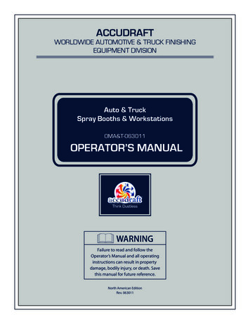
ACCUDRAFTWORLDWIDE AUTOMOTIVE & TRUCK FINISHINGEQUIPMENT DIVISIONAuto & TruckSpray Booths & WorkstationsOMA&T-063011OPERATOR’S MANUALWARNINGFailure to read and follow theOperator’s Manual and all operatinginstructions can result in propertydamage, bodily injury, or death. Savethis manual for future reference.North American EditionRev. 063011
Read this manual carefully and become familiar with your equipment. Know its applications, itslimitations and any hazards involved.WARNINGRISK OF EXPLOSIONNo vehicles with fuel are allowed in theworkspace. Vehicle battery must bedisconnected before the vehicle isbrought into the workspace.WARNINGTOXIC FUMESNever enter the system’s workspacein any running state other than theSPRAY/WORK period.WARNINGRISK OF ELECTRIC SHOCKDisconnect main power supply tocontrol panel before performing anymaintenance or service on thesystem.WARNINGHOT SURFACESSurfaces in or around the systemreach temperatures in excess of 150 Fand can cause burns. Do not touch hotparts.WARNINGTOXIC FUMESAlways wear approved attire andfresh air supply mask whenworking in the workspace.IMPORTANT SAFETY NOTICESAIMA of North America, Inc. is concerned with the protection of people and propertyfrom the hazards of improper use of process heating equipment and urges customers tocomply with national safety standards and/or insurance underwriter's recommendations.The owner/user and/or the insurance underwriter must assume responsibility for theacceptance, use, and proper maintenance of the purchased system. These responsibilitiesinclude, but are not limited to: filter changes, cleaning of the system in all areas, flamesupervision, periodic checks of limit controls and other safety devices.It is also recommended that any and all personnel entering the paint booth wear theapproved fresh-air supply equipment.It is further recommended that the owner/user periodically upgrade his process heatingequipment to comply with the latest national safety standards. (These standards areregularly updated to reflect technological improvements.)Furthermore, SAIMA of North America, Inc. strongly recommends a complete check up bya highly trained heating technician at least every six months.Accudraft products are supported by a network of authorized servicerepresentatives. For information on Accudraft products and services, please contactSAIMA of North America, Inc. at 1-800-524-0340.Accudraft carries all original filters and parts. For more information please call 1-800524-0340.NOTE: The technical & graphical information contained in this handbook is universal and isintended as a guide only. The information contained herein is accurate up to the printed date.However, continuous improvements and updating may change product specifications withoutprior notice. As a result, differences between Accudraft products and this handbook may occur.SAIMA of North America reserves the right to improve products without prior notice and is notliable for discrepancies between products and product guides/manuals. For any questions orbefore performing any work on Accudraft products, please contact SAIMA of North America Inc. oran authorized distributor/representative.
Table of ContentsPreface.4Safety Precautions.5General Features.6General Performance.7General Systems Operation.9System Controls.11SmartPad Control PanelPushbutton Control PanelMPS-5 Temperature ControllerNon-Heated System ControlsMechanical Groups.26KDModified KDTimelessStandaloneIndirect FireSS/VENTUSMaintenance Schedule.38Painting Suggestions.40Warranty.43
PrefaceThank you for choosing Accudraft products. Please read this entire guide beforeoperating your new finishing system. The purpose of this guide is to give you the generalknowledge needed to operate your system and maintain it properly for optimalperformance. This is not intended as a technical manual for service and/or installation. Ifyou have any questions, please contact SAIMA of North America Inc. at 1-800-524-0340 orvia email at info@accudraftpaintbooths.com.This manual is intended as a universal guide for the Accudraft systems listed below: TITAN XL ITALIA MX SS VENTUS TX PK3000 PREP 4000 MAGNUM 5000
Safety PrecautionsATTENTION: Always follow the precautions below:-Always use a fresh air supply or charcoal saturated mask during all spray operationsAlways use approved treated attire suitable for the spraying of paint and related coatingsNo smoking or open flames are allowed within 30 feet of the spray systemNo personnel are to be inside the heated work area during the bake cycleNo repair or modification is to be performed by an unauthorized partyCar batteries are to be disconnected before the vehicle is put in the booth/prepstation/spray areaNo fuel of any kind is to be present in the booth/prep station/spray area
General Features253189419101817112012761613141512. Lower Lights (Vertical or Horizontal)1. Intake Unit13. Downdraft Pit2. Recirculation Damper14. Connecting Tunnel3. Pre-Filters15. Mechanical Unit Pit4. Burner16. Exhaust Filters5. Intake Stack17. Exhaust Fan6. Intake Fan18. Adjustable Damper7. Intake Motor19. Exhaust Motor8. Air Connector20. Exhaust Unit9. Intake Plenum (Ceiling Plenum/Upper Plenum)10. Ceiling Filters11. Upper Angled Lights (Also called “Gable” or “Hip” Lights)
General PerformanceThis is a general description of the intended process followed by Accudraft productscovered by this operations guide.1. Fresh air is drawn through the intake duct by the intake fan or blower located in theAir Makeup Unit (AMU). For a non-heated Accudraft product that does not have anair makeup unit, please go to Point #8.2. The incoming air passes through a filter called a “Pre-Filter” located between theintake duct and the burner or heating element. This is the first stage of filtration andit ensures that debris from the outside air is not shortening the life of the criticalfilters encountered later in the airflow pattern. It also ensures that the air passingthrough the flame or heat exchanger is clean and free of contaminants and debris.3. The incoming air then passes through the burner flame (direct fire) or around thebody of a heat exchanger (indirect fire) causing the air to heat up. The temperaturesetting set by the user on the control panel will control exactly how high or low theburner’s intensity will be.4. The hot air then travels through the connecting duct to the upper ceiling plenumabove the spray booth workspace. This is the 12-18” inch tall section above theworkspace.5. Once this upper plenum is full of air and pressurized, the air flows downwardthrough the ceiling filters. This is the second and final stage of filtration before theincoming air enters the workspace. Supplied ceiling filters stop particles that are 5microns in diameter or bigger. When purchasing replacement filters, please ensurea minimum of 5 micron rated filters for the ceiling. (A micron is a metric unit ofmeasure. 1 Micron 1 Millionth of a Meter).6. Once the filtered air has entered the workspace, it is pulled out of the workspace viathe exhaust point which can be in several different places depending on the airflowconfiguration of your product (See diagrams & details in the next chapter).7. Once the air has reached the exhaust point, one of two things will take placedepending on the system’s cycle. The exhausted air will either be completelyexhausted to the outside atmosphere or will be re-circulated past the burner. Thelist below describes the four main cycles found in any Accudraft finishing systemand the respective intake/exhaust pattern.a. Spray Period – 100% Fresh Air In/100% Exhausted Air Outb. Flash Cycle - 100% Fresh Air In/100% Exhausted Air Outc. Bake/Cure Cycle – 15-20% Fresh Air In/80-85% Recirculated/15-20% Exhausti. For non-recirculating or “full flow” applications, this period will alsobe 100% Fresh Air In/100% Exhausted Air Out.d. Cool Period - 100% Fresh Air In/100% Exhausted Air OutNOTE: Also see section titled Cycle Sequence.
General Performance(continued)8. For a non-heated Accudraft product that does not have an air make up unit (AMU),the system operates on a simple exhaust principle. Air is exhausted out of theworkspace and the incoming is drawn naturally into the workspace from theenvironment outside the spray booth. This air travels through the booth/system’sinterior workspace to the system’s exhaust point. The incoming air is drawn fromthe environment immediately adjacent to the system (usually the shop). Pleasecheck with local codes that this type of system is suitable for your location. If propermeasures are not taken, the entire building may become “negatively pressurized”when the system is in use, making shop or building doors/windows hard to open.Doors and windows may also open on their own depending on hinge direction.Preventative measures may include dampers or vanes in the building to avoidthese unwanted pressurization issues or an air make up unit (AMU) may be requiredby code.
General System Operation1. Turn the on/off key to the “on” position. Turn on Lights.2. Have the piece or vehicle to be painted ready to be driven inside the workspace.3. Wear the approved fresh air supply mask and treated protective suit. Transfer allmaterials necessary for completion of the refinishing process to the inside of thebooth.4. Open the main entry doors.5. Drive the vehicle slowly into the booth and park it in the center of the booth. Closethe doors immediately.6. Start the system to begin the Spray/Work Cycle. Adjust temperature if necessary.Work temperature should be between, 65 and 80 degrees and should be comfortablefor the user to work in.7. Following the paint manufacturer’s recommendations for preparing before painting,proceed to insure total cleanliness of the vehicle and the painter.a. NOTE: Accudraft (SAIMA of North America Inc./SAIMA Meccanica S.p.A)does not guarantee any level of quality or performance in regards to finishquality and/or drying speed of the coating being applied. Many variablesexist for the introduction of contaminants to the workspace and for theextension of curing times. Some of those factors include, but are notlimited to debris being introduced into the workspace by theworker/vehicle/tools, negligent filter maintenance, and improper paintingand preparation procedure. Any claims made against the equipment orSAIMA of North America Inc. for finish quality/time issues will not berecognized. The only guarantee supplied with this product is on theproduct materials themselves. The warranty can be found on the finalpage of this user’s guide.8. Proceed with the refinishing process. Strictly follow the paint manufacturer’srecommendations. Never smoke or have an open flame in the cabin.9. Complete the painting process.10. Remove any and all excess paint material (paint, reducers, spray gun, air hose,tacking rag, tape, etc .) from inside the cabin and close the doors.
General System Operation(continued)11. Advance the system into the BAKE/CURE process. THE USER SHOULD NOTOPEN ANY DOORS OR ENTER THE WORKSPACE DURING THE CURINGCYCLE.12. The internal lighting will turn off. The system will purge for a minimum of 3 minutes(PURGE/FLASH period). Once the PURGE/FLASH period is expired, the system willautomatically move to the BAKE period. The BAKE period will run for the time selectedand will then automaticaly enter the COOL period. Once the COOL period is finished,the system will automatically stop and workspace lighting will turn on again.13. If you have any problems with any of these steps, please contact an authorizedtechnician. Remember, a repair of any kind should always be done by an authorizedtechnician.
System ControlsAccudraft finishing systems are provided with either pushbutton or digital controls.In the following section, please find the control panel that applies to your system.Pushbutton ControlsSmartPad Digital Controls
SmartPad Basic OperationSpray/WorkFlash PeriodBake PeriodCool PeriodStatic PressureReadingBurner On/OffButtonFLASHPressMain Screen says “No.1” which is Mode 1 for standard coatingsIn Mode 1 - Booth goes to bake cycle automaticallyIf you are spraying standard High VOC coatings, pressIn Mode 2 - System returns to SPRAY/WORK.If you are spraying low VOC or water-based coatings press P againMain Screen says “No.2” which is Mode 2 for low VOC coatingsPressreturn to SPRAY/WORK.NOTE: For VFD systems, system starts and runs at “standby” rateTo go to FINAL FLASH period in Mode 2, press theOnce spraying is detected, the system will run at full powerIf spraying stops for 90 seconds or more, the system will returncycle and all other cycles automatically.to “standby” rateMode 1: PressKeyMode 2: PressKeyThis will put the system into the FLASH PeriodKey.
1SmartPadLegend & Advanced Functions822491810193111242013215141562216172371. Temperature Reading Display - Displays the current temperature of the workspace2. SPRAY/WORK Period Temperature Setting Display - Displays desired temperature for the SPRAY period3. FLASH Period Temperature Setting Display - Displays desired temperature for the FLASH period4. BAKE Period Temperature Setting Display - Displays desired temperature for the BAKE period5. COOL Period Temperature Setting Display - Displays desired temperature for the COOL period6. Static Pressure Reading Display - Displays the current static pressure found in the workspace.
SmartPad Legend & Advanced Functions(continued)7. Timer/Hour Meter/Password Display - Displays cycle times and total hours of use. Also used whenentering the password for the Auto-Tune function.7a. When the system is running - Displays the time left in the current cycle7b. When the system is off - Displays the total number of operation hours on the system7c. When entering the password for the Auto-Tune function - Displays the numeric password8. Temperature Unit Display - Displays either “Degrees Fahrenheit” ( F) or “Degrees Celcius” ( C)9. START button - Starts the system10. P button - Selects the type of finishing program before the system is started and is used totoggle through setting parameters.button once to select standard mode (No.1)10a. Before starting the system, press the10b. Press thebutton a second time to select the Waterborne or Low VOC mode (No.2)11. RIGHT ARROW button - Advances to the next cycle in sequence11a. Press once to advance from SPRAY period to the automatic process cycles (flash, bake, cool)NOTE: When in Waterborne/Low VOC mode (No.2) the system will advance to flash butwill return to the spray period for a second spray coat. Press theagain to advance tothe automatic process cycles. After the second time, the automatic cycles will take overthe system as normal. For more details, see section titled “System Operation.”11b. While in any automatically timed cycle, press and hold to skip immediatly to the next cycle12. UP ARROW button - Increases any setting or parameter being adjusted13. DOWN ARROW button - Decreases any setting or parameter being adjusted14. CLOCK button - Used to adjust cycle time settings and adjust cycle times on the fly14a. To adjust any cycle’s default time setting, first press the cycle icon button you wish to adjustand then press thebutton (both button LED lights will be blinking in unison). Adjust thedefault cycle time using thearrow buttons. The default cycle time is displayed on theleft of the TIMER/HOUR METER display. When the desired time setting is set, press thebutton again to save it. All LED’s will stop blinking and the system will save the new setting.Default time settings can be changed with the system off or while it is running. The SPRAY/WORK period is not adjustable as it has no time setting.14b. To adjust any cycle’s remaining time on the fly, press thebutton while in any cycle(except the SPRAY/WORK period as this period has no time setting). The clock button LEDlight will blink. Adjust the remaining cycle time using thearrow buttons. The remainingcycle time is displayed on the right of the TIMER/HOUR METER display and is blinking. When thedesired remaining time is set, press thebutton again to resume the countdown. Remainingtime settings can be changed only while the system is running.15. % OUT button - This is used to adjust the power of the exhaust unit when a VFD (Variable FrequencyDrive) is installed for the exhaust motor (From Accudraft Only - 3rd party VFD’s added after installation of the system will not have this function).button and adjust the exhaust power using the15a. While the system is running, press thearrow buttons. When the desired power is achieved, press thebutton again. Thesetting has now been changed and will remain at that percentage until adjusted again.NOTE: If the system was purchased with “Automatic Pressure Regulation” as a feature, this button isonly active for manual adjustment during the BAKE period.CAUTION: When replacing soiled filters, be sure to re-adjust exhaust setting and open all doorsbefore starting the system with clean filters. Failure to do so, may cause a negative pressuresituation. This may result in damage to the equipment.
SmartPad Legend & Advanced Functions(continued)16. LIGHT BULB (1) button - Controls the first series of light fixtures (Push - ON, Push again - OFF)17. LIGHT BULB (2) button - Controls the second series of light fixtures (Push - ON, Push again - OFF)18. SPRAY/WORK period button - Press to adjust temperature setting for the SPRAY/WORK period18a. Press thebutton (the LED will blink) and use thearrow buttons to adjusttemperature setting shown in the adjacent display window. Press thebutton againto save.19. FLASH cycle button - Press to adjust time & temperature settings for the FLASH cycle19a. Press thebutton (the LED will blink) and use thearrow buttons to adjusttemperature setting shown in the adjacent display window. Press thebutton againto save.19b. To adjust FLASH cycle time see #14 “Clock button” on the previous page.20. BAKE cycle button - Press to adjust time & temperature settings for the BAKE cycle20a. Press thebutton (the LED will blink) and use thearrow buttons to adjusttemperature setting shown in the adjacent display window. Press thebutton againto save.20b. For systems with the Intellicure rapid surface temperature feature, the BAKE period has twotemperature settings. To access the first temperature setting, press thebutton once. Thefirst temperature displayed is the high temperature setting which is typically set 20 degreeshigher than the standard bake temperature (160 -180 F). Adjust to the desired temperatureusing thearrow keys. This is the first BAKE period and lasts on average 10-15 minutes. Toaccess the second (standard) BAKE temperature setting, press thebutton a second timeand adjust the temperature setting using thekeys.Press thebutton again to save settings.20c. To adjust BAKE cycle time see #14 “Clock button” on the previous page.21. COOL cycle button - Press to adjust time & temperature settings for the COOL cycle21a. Press thebutton (the LED will blink) and use thearrow buttons to adjusttemperature setting shown in the adjacent display window. Press thebutton againto save.21b. To adjust COOL cycle time see #14 “Clock button” on the previous page.22. SP button - Press to adjust the workspace static pressure setting (active only on systems purchasedwith the Automatic Pressure Regulation feature).22a. Press thebutton (the LED will blink) and use thearrow buttons to adjuststatic pressure setting shown in the adjacent display window. (.04 - .08 is the recommendedstatic pressure setting). Press thebutton again to save the new static pressure setting.NOTE: To adjust workspace pressure while the system is running, adjust dampers or fan speeds tomaintain gauge needle slightly above 0. ALL DOORS MUST BE CLOSED FOR PRESSURE READINGTO BE ACCURATE. IF PRESSURE PROBLEMS PERSIST, CHECK 1/4” PLASTIC TUBE PROTRUDING INTOTHE WORKSPACE. THIS IS THE SENSOR TUBE AND IT CAN BE CLOGGED EASILY WITH BOOTH WRAPPING/SPRAYS.23. STOP button - Press once to skip straight to the COOL cycle. Press again to stop the system completely.24. BURNER ON/OFF button - Pressbutton to disable the burner.24a. During summer months you may choose to disable the burner during the SPRAY/WORK period24b. If burner has been disabled during the SPRAY/WORK period, It is not necessary to re-activatethe burner before proceding to the next cycle. The burner will automatically re-activate oncethe user has advanced the system to the automatically timed cycles (FLASH, BAKE,COOL).
SmartPad Auto-Tune Function1. Set temperature to 100 F2. Press and hold thearrow buttons simultaneously for five seconds until the letters c.n.f. appear in the SPscreen.3. Using thearrow buttons, enter the number 12 in the green hour meter screen.4. Press thebutton until the letters A.t. appear in the SP screen.5. Using thearrow buttons, enter the number 1 in the green hour meter screen6. Press thebutton until the control panel returns to the normal “home” display.7. To confirm that the system is performing an Auto-Tune, observe the current temperature reading in the largescreen at the top of the control panel. If this number is blinking, the system is in the process of an Auto-Tune.When the Auto-Tune is done, the temperature reading will stop blinking and the system will return to normaloperation.NOTE: During the auto-tune, the temperature will overshoot and undershoot the target temperature as part ofthe calibration.NOTE: Auto-tuning can last between 5 and 15 minutes depending on outside temperatures. Please wait untilthe auto-tune is finished before resuming normal use of the spray booth or system.NOTE: Auto-tunes should be conducted a minimum of twice a year or with the change of seasons to accountfor changes in outdoor temperatures.NOTE: For best results, perform auto-tunes at temperatures below 85 F and make sure all filters in the systemand mechanical units are clean or brand new.
Pushbutton Control PanelBasic OperationSpray/WorkBake ProcessLights On/OffBurner On/OffMaster On/Off1. Turn MASTER switch/key to ON (1)- Bake time may be decreased during the2. Turn BURNER switch to ON (1)BAKE process by turning the timer lens3. Turn LIGHTS switch to ON (1)counter clockwise. Bake time cannot be4. Press the SPRAY/WORK button.- To adjust temperature useincreased during the BAKE process.on thetemperature controller. For temperaturecontroller settings, see section titled“MPS-5 Temperature Controller”- The system will run in SPRAY/WORK untilthe user starts the BAKE processOnce finished with spraying:5. Turn TIMER lens clockwise to select desired BAKE time6. Press the BAKE Process button:- System will advance into the automaticcuring processes. The process begins first withFLASH/PURGE period and will progress throughthe BAKE period final COOL period.- Lighting will be off during the curing processWhen all processes are finished, the system will shutdown and workspace lighting will return.7. To start the next job, turn MASTER switch to theOFF position (0) and turn the switch back to theON positioon (1).To adjust workspace pressure while the system isrunning, adjust dampers or fan speeds to maintaingauge needle slightly above 0. ALL DOORS MUSTBE CLOSED FOR PRESSURE READING TO BE ACCURATE. IF PRESSURE PROBLEMS PERSIST, CHECK 1/4”PLASTIC TUBE PROTRUDING INTO THE WORKSPACE.THIS IS THE SENSOR TUBE AND IT CAN BE CLOGGEDEASILY WITH BOOTH WRAPPING/SPRAYS.
Pushbutton ControlsLegend & Advanced Functions113231211104567891. MAGNEHELIC GAUGE - Displays the current pressure inside the workspace1a. Recommended positive pressure is slightly above (0).NOTE: Avoid negative pressure. If needle is resting on the peg below the 0 mark, the pressurein the workspace is negative. Close exhaust damper slowly until needle rises and staysslightly above 0. If this does not work, change intake & ceiling filters.2. COOL Period Indicator Light - Illuminates when in the COOL period.
Pushbutton ControlsLegend & Basic Functions(continued)3. MPS-5 Temperature Controller - Used to input desired temperatures. Displays desiredtemperature and actual temperature during any operation. See chapter titled “MPS-5 TemperatureController”4. TIMER for BAKE Cylce - Used to set the desired bake time. Turn round lens clockwise to set desired time5. SPRAY/WORK Period Button and Indicator Light - Starts the system in the Spray/Work Period. Indicatorwill illuminate.6. BAKE Period Button and Indicator Light - Advances the system into the automatic FLASH, BAKE, COOLcycles. TIMER must be run up first, then the BAKE button is pressed. FLASH period will start. Indicatorwill illuminate.7. LIGHTS On/Off Switch and Indicator Light - Controls the workspace lighting (0 Off, 1 - On). Indicator willilluminate when lights are ON.NOTE: During automatic FLASH, BAKE, COOL cycles, on/off switch is overridden and lighting willbe OFF.8. BURNER On/Off Switch and Indicator Light - Controls the heating system’s burner (0 Off, 1 - On).Indicator will illuminate when burner is ON.NOTE: Fan will continue to run. This switch only shuts down/turns on the burner unit in theSPRAY/WORK period. The burner will automatically turn on during the BAKE cycleregardless of switch position.9. MASTER On/Off Switch and Indicator Light - Turns on the control panel (0 Off, 1 - On). Indicator willilluminate when control panel is ON.NOTE: This switch may be a standard on/off switch or a lock & key switch that is supplied withtwo copies of the key.10. MAINTENANCE ACCESS LOCK - Allows access to the internal wiring of the control panel.11. HOUR METER - Shows total hours of use on the Accudraft system.12. DISCONNECT 2 - Disconnects the second power feed from the building13. DISCONNECT 1 - Disconnects the first power feed from the building
MPS-5 Temperature ControllerStandardIntellcure MPS 5MPS yitmitmThe MPS-5 temperature controller is available in Standard and Intellcure versions.Both are physically identical. To find out which one is used in your system, please locate the product labelon the side of the controller and see the following pages for instructions on how to program.Indicates Type of ControllerMPS3 P4 01 00 00 0SCALEPT100INPUT0 -200 FSUPPLY30/250 VS.N.276103L 7D i re c t Fi reS 7 I nte l l i c u re ( Up to 4 T i m e / Te m p e rat u re S e ttings)L 7 2 S e t p o i nt ( 2 T i m e / Te m p e rat u re S e t t i n g s )I n d i re c t Fi reL 7 2 S e t p o i nt ( 2 T i m e d / Te m p e rat u re S e t t i n gs Only))(5c A50/60Hz 5V AIndicates Type of BurnerA D i re c t Fi re - m i l l i A M P O u t p u tV D i re c t Fi re - Vo l t a g e O u t p u tR I n d i re c t Fi re - R e l ay O u t p u t
MPS-5 Temperature ControllerLegend & Advanced Functions1243912MPS 5PVATSVMAL1SP1AL2SP2AL351110Pbyitm6781. Temperature Reading Display - Displays the current temperature of the workspace- This is the actual temperature reading from inside the workspace. The temperature sensor shouldbe visible from inside the workspace. Mounting the sensor in other locations can cause inaccuratereadings and burner malfunctions.2. Temperature Setting Display - Displays desired temperature for the current period- This is the temperature your system is currently calling for. (This value changes depending on theperiod the system is in“Spray”,“Flash”, ”Bake”,“Cool”)button.2a. To change temperature settings press the3. M Indicator Light - Indicates that the main output relay is energized4. SP1 Indicator Light - Indicates that Set Point 1 (temperature setting for SPRAY/WORK) is currently active.5. SP2 Indicator Light - Indicates that Set Point 2 (temperature setting for the BAKE/CURE process) iscurrently active.NOTE: Intellcure controllers may have more than one temperature setting within the BAKEprocess itself. This is still only expressed with the SP2 Indicator on.6. UP Arrow Button - Used to adjust settings7. DOWN Arrow Button - Used to adjust settings8. P Button - Used to program the controller9. AL1 Button - Alarm relay 1 - Not used, but available for connection of alarm switches if necessary.10. AL2 Button - Alarm relay 2 - Not used, but available for connection of alarm switches if necessary.11. AL3Button - Alarm relay 3 - Not used, but available for connection of alarm switches if necessary.12. Auto-Tune Indicator Light - Illuminates only when the system is performing an auto tune- See sections titled “Auto Tune Function”.NOTE: Intellcure and 2-Set Point controllers have different Auto-Tune instructions.
2 Set-Point Controller** All temperature controllers come preprogrammed.To access the programming mode:SPRAY/WORK PeriodNo Time LimitBAKE Period30-40 Minutes1. Press & hold the button until b.L.o. appears on the SV screen.2. Using thearrow, enter the number 0 on the PV screen.until the controller returns to the normal “home’ display.3. PressTemperature programming:1. Press the button until SP1 appears on the SV screen.2. Using thearrows, enter the desired temperature for theSPRAY/WORK period.3. Press thebutton until SP2 ap
Auto & Truck Spray Booths & Workstations OPERATOR'S MANUAL OMA&T-063011 WARNING Failure to read and follow the Operator's Manual and all operating instructions can result in property damage, bodily injury, or death. Save this manual for future reference. North American Edition Rev. 063011