Transcription
Eye Doctor IIAdvanced Signal Integrity Tools
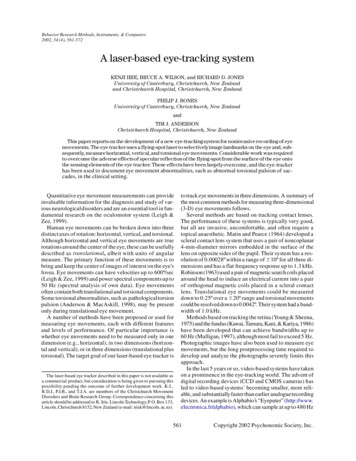
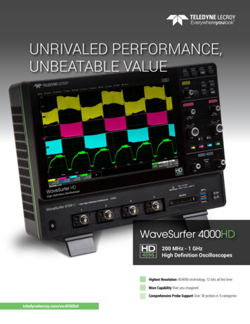
EYE DOCTOR II ADVANCED SIGNAL INTEGRITY TOOLSKey Features Eye Doctor II providesthe channel emulationand de-embedding toolsTools for Next GenerationSerial Data Standardsneed new tools to remove theAs signal speeds and data ratesmodel the impact of serial datahave increased to 5 Gb/s and greaterchannels and fixtures, and simulatewhile propagation mediums havethe receiver equalization. Theseremained unchanged, engineers havecapabilities greatly enhance thehad to face new challenges withability to make useful measurementssignal integrity. These faster signalin high-speed circuits. Additionally,speeds give rise to increased attenu-newer serial data standards areation in the frequencies of interest.requiring such tools in order to makeThese effects were small enough tocompliance measurements. For ex-ignore at lower bit rates, but asample, PCI Express 3.0 will requirerise times get faster and serialthe use of fixture de-embedding todata rates increase, these effectsrefer the compliance measurementmust be accounted to avoidback to the pins of the transmitter;unacceptable intrusion into theSuperSpeed USB requires the use of Ability to read single ended ordesign margin or completelycontinuous time linear equalizationunusable measurement results.being applied in the oscilloscope DFE, FFE and CTLE ReceiverAs data rates increase, losses due tosoftware, SATA 6 Gb/s and 6 Gb/sthe serial data channels andSAS require the emulation of thefixtures increase at high frequencyTransmitter Compliance Transferleading to eye closures. To trulyFunction (TCTF) to simulate theunderstand jitter in the serial dataworst allow case channel forsignal, these effects must bedebugging compliance failures. dds precision to signalAintegrity measurements ital for anyone using anV8 GHz or higher oscilloscope Seamlessly integrates intoTeledyne LeCroy’s SDA II andSDAIII-CompleteLinQsoftware for eye diagramand jitter analysis Creates eye diagrams 50x fasterthan existing solutions Uses industry standardTouchstone format S-parameterfiles for fixture and channeldefinitionmixed mode S-parameter filesEqualization Fully integrated into the userinterface which allows theengineer to use additionalTeledyne LeCroy tools forpost-processing Use Eye Doctor II’s Advancedimpact of test fixtures and cables,removed. Clearly, design engineersmode to: – Flexibly arrange componentsto allow any combination ofde-embedding or emulationfor Virtual Probing of anypoint in the test circuit nototherwise accessible – Increase measurementaccuracy through theuse of a more advancedtransmitter and receivertermination model thatincorporates customerspecific characteristics2Eye Doctor II main user interface.Integrates into SDAIII-CompleteLinQFor more information:teledynelecroy.com /sdaiii
3
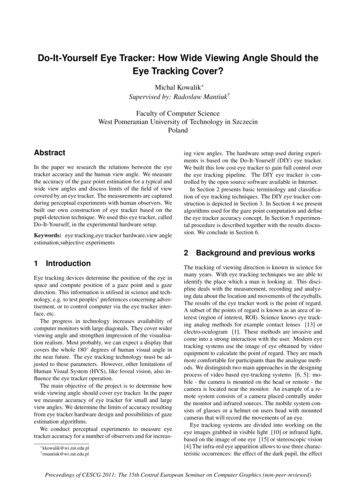
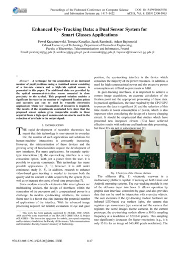
EYE DOCTOR II CAPABILITIESRxTxEMPHASISEQUALIZATIONEmulating Serial Data Link ComponentsRxto properly characterize the robustTx performing serial data measurements on the physical layer, the main goal isWhenCHANNELness of the serial data link. Measurements can either be made at the transmitter or the receiver as shown IZATIONCHANNELTxDe-embedding Fixture from Tx COPEDe-embedding Fixture from Rx xOSCILLOSCOPECHANNELFIXTURECable De-embeddingOSCILLOSCOPECable de-embedding is a standard feature on all SDA Zi/Zi-A oscilloscopes and is included with Eye Doctor II.CHANNELCable de-embedding gives the user the ability to quickly andeasily remove the effect of cables by enteringFIXTUREOSCILLOSCOPEin an attenuation table or attenuation constants that are typically provided by the cable manufacturer.4
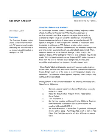
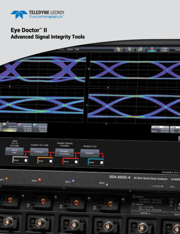
EYE DOCTOR II ADVANCED SIGNAL INTEGRITY TOOLSAs signal speeds and data rates haveincreased to beyond 5 Gb/s whilepropagation mediums have remainedunchanged, engineers have facednew signal integrity challenges,among these, increased attenuationin the frequencies of interest. Theseeffects were small enough to ignoreat lower bit rates, but now theseeffects must be accounted for toavoid unacceptable intrusion into thedesign margin or completely unusablemeasurement results.Serial data signal probed atthe transmitter output shows acceptable responseLosses in the serial datachannel affect the signalintegrity. This effect can bede-embedded or emulatedThe receiver usually applies equalization to “open” theeye. This equalization canbe modeled to show how the signal appears to the receiver afterequalization is appliedAdding/Removing Pre- orDe-emphasisresult. The measurement result is thenincorporates equalization to compen-Transmitter designers sometimesunaltered by the test setup, andsate for losses associated with theemploy the use of emphasis to pre-the ability to further measure, applyserial data channel. Losses fromcompensate for these effects. Eyemath, or post-process this truethe channel can cause the eye to beDoctor II can remove de-emphasis ormeasurement using additional tools,completely closed at the input of thepre-emphasis from a signal measuredsuch as parameters, math functions,receiver. Even though a receiver thatat the transmitter output. This is usefuljitter tracks, histograms, eye diagrams,utilizes equalization would be able towhen attempting to measure the jitteretc. is available.properly decode this signal, theSerial Data Channel ResponseEmulationoscilloscope jitter analysis software willon such a signal in order to remove theDDj introduced by the de-emphasis.Eye Doctor II can also add de-emphasisor pre-emphasis to quantify thecompensation necessary for specificserial data channels.Cable/Fixture/Serial DataChannel De-embeddingMost commonly, a design engineerwill perform their serial data measurement at the output of the transmitter.However, the engineer may also beinterested in referring their measurement to the far side of a particular serialnot be able to recover a clock from thesignal and will not be able to performany jitter analysis. For this reason, theoscilloscope emulates the differentequalizers the engineer’s receiver couldbe using and thus provides the ability toview the eye diagram and jitter performance on the signal as it is actuallyIn many typical high frequencydata channel. To accomplish this theymeasurement situations, engineerscould either use a physical channeldesire to connect as directly to theirand make their measurement after theLearn Moresignal as possible and avoid the use ofchannel or they can use channel emula-teledynelecroy.com/dl/1023probes. However, even high quality testtion to see what their serial data signalteledynelecroy.com/vid/M0T6WEC0JYQfixtures, channels, and cables have awould look like if it had been trans-teledynelecroy.com/dl/1216negative impact on signal quality thatmitted through the channel.increases with higher signal frequency.teledynelecroy.com/dl/1136This is particularly useful for someIf the test fixture, channel, or cable cancompliance testing.be electrically quantified in terms ofS-parameters, then its electrical impactcan be removed from the measurementseen by the specific receiver.Receiver EqualizationFinally, the serial data receiver often5
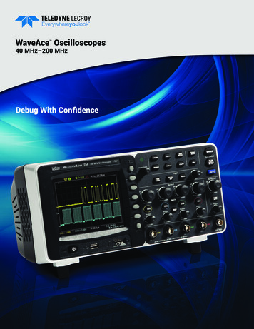
TRANSMITTER EMPHASIS EMULATION1After2Before1. T eledyne LeCroy’s Eye Doctor IIAdvanced Signal Integrity Toolsprovide the ability to impose theeffects of a channel or an equalizeron a measured signal. Eye Doctor IIallows the subtraction of fixtureeffects, and the emulation of3emphasis, serial data channels,and receiver DFE, FFE, and CTLEequalization effects and integratesseamlessly into Teledyne LeCroy’sSDA II software for eye diagramand jitter analysis.2. N otice that the Signal Input is setto Channel 2 minus Channel 3and the Nominal Bit Rate is set4to 5 Gb/s.3. A s you can see this eye diagramcontains de-emphasis. Thisde-emphasis can be removedfrom the signal so that the eyediagram can be observed withoutthe de-emphasis.54. T he pre- or de-emphasis caneither be added or removed. Inthis case, it is set to remove3.5 dB of de-emphasis.5. T he eye diagram is calculatedand displayed with thede-emphasis removed.6
FIXTURE DE-EMBEDDING6AfterBefore6. F ixtures and the attached cables7can be de-embedded to see whatthe eye would actually look likedirectly at the transmitter output.The Emulate/De-embed menuhas three choices.7. H ere “Emulate Channel/de-embedFixture” has been chosen.8. T he S-parameter file that contains8the fixture response informationis an industry-standardTouchstone file format. Simplybrowse for the file and select theappropriate file for the fixture youare using. The user must firstmeasure or simulate the lossy9fixture and then copy it to theoscilloscope.9. C licking “Apply” will now de-embedthe fixture.The previous eye diagram shown on page 6 now shows the result with the fixture and cablesde-embedded.7
CHANNEL RESPONSE EMULATION10AfterBefore10. In addition to cable and fixturede-embedding, serial data channelsmay also be emulated. Again,the S-parameter file defining the11channel is selected and applied.If the ports in the S-parameter fileare different from those shown,the ports used can be reassignedvia the dialog. The user must firstmeasure or simulate the lossychannel and then copy it to theoscilloscope.11. T he “View Response” feature12allows the user to view a plot of anyof the s-parameters in the Touchstone file being used, and allowsverification of correct setup. In thiscase, “S21” and “Magnitude” areselected to show the insertion loss.12. T he Emulate/De-embed menushows the setup as defined, with13the S-parameter file names usedconveniently displayed in the userinterface, at the bottom.13. N otice how the Eye diagrambegins to close and the ISIincreases when the channelis emulated. This provides insightinto how a serial data channel thatis not present in the test circuitwill affect the serial data signal.The previous eye diagram shown on page 7 now includes the effects of anemulated serial data channel.8Additional Teledyne LeCroy tools,such as masks or IsoBER, can beapplied on this eye diagram.
RECEIVER EQUALIZATION14AfterBefore14. R eceiver Equalization can allow15insight into how the receiver willcorrect for a “closed eye” situation. In this example, a receiverthat employs FFE equalization issimulated. The number of tapsis set to five and the number ofprecursor taps is set to three. Levels are automatically foundby the software.15. W ith equalization applied, theeye opening widens from thatshown on page 8.16. T he main Eye Doctor II user16interface displays all of theprocessing steps that arecurrently being performed directlyunder each processing block.The Teledyne LeCroy Eye Doctor II Advanced Signal Integrity Tools addprecision to your signal integrity measurements, re-capture design marginlost to test fixtures and cables, allow you to support PCI Express 3.0, SATA6 Gb/s, SuperSpeed USB and 6 Gb/s SAS. When used with TeledyneLeCroy’s SDA II software, Eye Doctor II provides fast eye diagram and jittermeasurement analysis results using the de-embedded and emulated data onfull record lengths.9
MOST ADVANCED EQUALIZATIONEye Doctor II has advanced equalization capability thatthe independent equalization of the data signal and theallows the user to perform Continuous Time Linearsignal that is used for clock recovery. This ability is veryEqualization (CTLE), Feed Forward Equalization (FFE)important for serial data standards such as 6 Gb/s SAS.and/or Decision Feedback Equalization (DFE) on theirThese signals could have closed eye diagrams in whichdata signal. Additionally, the data signal after the CTLEsome form of equalization must be performed on theor FFE blocks can be used for clock recovery.data prior to recovering the clock signal. However, theAs seen in the image above, a simple user interfacegives the user access to all three of these equalizationmethodologies. Each equalization type (CTLE, FFE andbe the only form of equalization used on the data signal.Eye Doctor II makes this possible.DFE) can be separately enabled or disabled, and eachAdditionally the Feed Forward Equalizer and the Decisionhas a caption showing its current state. Clicking on theFeedback Equalizer have the ability to automatically trainCTLE, FFE, DFE or Clock Recovery boxes brings theto find the optimal tap values. User defined tap values canuser to the configuration page for that selection. Thealso be entered.Data Path to DFE In selection can be set to From EqInput, From CTLE or From FFE. Making one of theseselections updates the user interface showing the correctconnection between the data signal and the DFE input.These different configurations make it possible to have10standard also requires that Decision Feedback EqualizationEye Doctor II contains two separate waveform outputs:EyeDrOut and EyeDrClk. These signals can be used asinputs to SDA II for Eye Diagram and Jitter analysis onthe equalized data and clock signals.
SPECIFICATIONS AND ORDERING INFORMATIONSpecificationsFeature or CapabilityEye Doctor IICable De-embeddingFixture De-embeddingChannel De-embeddingEmphasis EmulationChannel EmulationReceiver Equalizer EmulationRecord LengthSingle-ended S-parametersMixed mode S-parametersNon-ideal Termination Models*YesYesYesYesYesDFE, FFE, CTLEUp to 512 MptsYesYesYes* Advanced Mode capability.Ordering InformationProduct DescriptionEye Doctor IIAdvanced Signal Integrity Tools forLabMaster 10 Zi OscilloscopesEye Doctor IIAdvanced Signal Integrity Tools forLabMaster 9 Zi-A OscilloscopesEye Doctor IIAdvanced Signal Integrity Tools forWaveMaster 8 Zi/Zi-A Oscilloscopes,SDA 8 Zi/Zi-A Serial Data Analyzers,and DDA 8 Zi/Zi-A Disk Drive AnalyzersEye Doctor IIAdvanced Signal Integrity Tools forWavePro 7 Zi Oscilloscopes,SDA 7 Zi Serial Data Analyzers, andDDA 7 Zi Disk Drive AnalyzersEye Doctor IIAdvanced Signal Integrity Tools forWaveRunner 6 Zi OscilloscopesProduct tomer ServiceTeledyne LeCroy oscilloscopes and probes are designed, built,and tested to ensure high reliability. In the unlikely event youexperience difficulties, our digital oscilloscopes are fullywarranted for three years and our probes are warranted forone year. This warranty includes: No charge for return shipping Long-term 7-year support Upgrade to latest software at no chargeWPZi-EYEDRII*WR6Zi-EYEDRII***SDAIII software is required for eye diagram and jitter analysis.**SDA II software is required for eye diagram and jitter analysis.11
1-800-5-LeCroyteledynelecroy.comLocal sales offices are located throughout the world.Visit our website to find the most convenient location. 2017 by Teledyne LeCroy, Inc. All rights reserved. Specifications, prices, availability, and delivery subject to changewithout notice. Product or brand names are trademarks or requested trademarks of their respective holders.eyedoctorIIds-10jul17
1. Teledyne LeCroy's Eye Doctor II Advanced Signal Integrity Tools provide the ability to impose the effects of a channel or an equalizer on a measured signal. Eye Doctor II allows the subtraction of fixture effects, and the emulation of emphasis, serial data channels, and receiver DFE, FFE, and CTLE equalization effects and integrates