Transcription
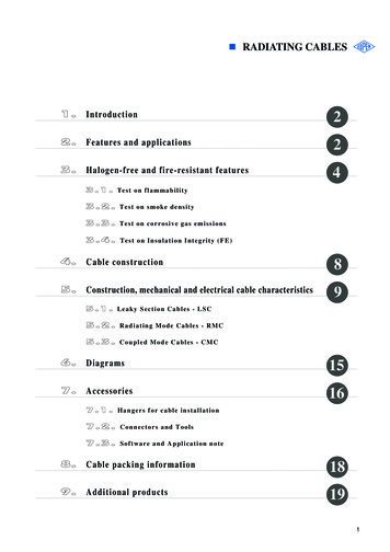
UNRIVALED PERFORMANCE,UNBEATABLE VALUE200 MHz - 1 GHzHigh Definition OscilloscopesHighest Resolution HD4096 technology, 12 bits all the timeMore Capability than you imaginedComprehensive Probe Support Over 30 probes in 9 categoriesteledynelecroy.com/ws4000hd
HighestResolution12 bits all the time.MoreCapabilityComprehensiveProbeSupport2
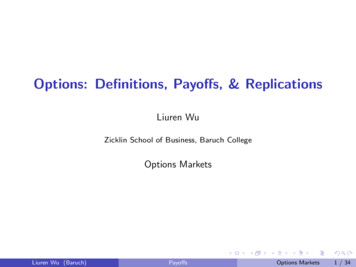
UnrivaledPerformance,UnbeatableValueWaveSurfer 4000HD extends Teledyne LeCroy’s leadershipin High Definition Oscilloscopes with a bright,12.1" touch screen display, performance withoutcompromise, and price points that fit your budget.12 bits all the time.3
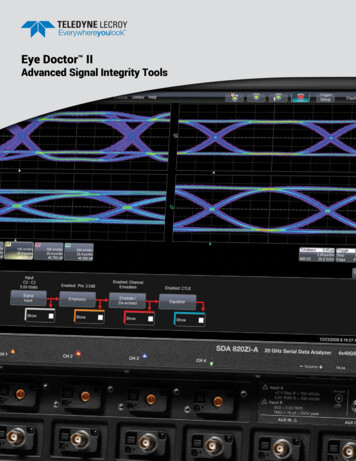
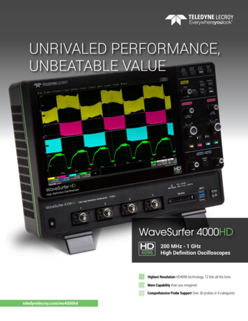
HD4096 TECHNOLOGY - 12 BITS ALL THE TIMETeledyne LeCroy high definition 12-bit oscilloscopesuse unique HD4096 technology to provide superiorand uncompromised measurement performance:– 12-bit ADCs with high sample rates– High signal-to-noise amplifiers– Low noise system architecture (to 1 GHz)Oscilloscopes with HD4096 technology have higher resolutionthan conventional 8-bit oscilloscopes (4096 vs. 256 verticallevels) and low noise for uncompromised measurementperformance. The 12-bit ADCs support capture of fast signalsand oscilloscope bandwidth ratings up to 1 GHz, while 5 GS/ssample rate ensures the highest measurement accuracy andprecision. The high performance input amplifiers deliver pristinesignal fidelity, and the low-noise system architecture providesan ideal signal path to ensure that signal details are deliveredaccurately to the oscilloscope display – 16x closer to perfect.HD4096 12-bitoscilloscope16x Closer to PerfectConventional 8-bitoscilloscope16x more resolutionHD4096 technology provides 12 bits ofvertical resolution — 16x more resolution thanconventional 8-bit oscilloscopes. The 4096discrete vertical levels reduce the quantizationerror compared to 256 vertical levels. Thisimproves the accuracy and precision of thesignal capture and increases measurementconfidence.Analog signal4
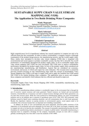
EXPERIENCE THE DIFFERENCEExperience HD4096 accuracy, detail, and precision and neveruse an 8-bit oscilloscope again. Whether the application isgeneral-purpose design and debug, high-precision analog sensors, power electronics, automotive electronics, mechatronics,or other specialized applications, the HD4096 technology provides unsurpassed confidence and measurement capabilities.Clean, crisp waveformsMore signal detailsUnmatched measurement precisionWhen compared to waveforms acquired16x more resolution provides moreHD4096 technology deliversand displayed using conventional 8-bitsignal detail. This is especially helpful formeasurement precision severaloscilloscopes, waveforms capturedanalyzing wide dynamic range signalstimes better than conventional 8-bitwith HD4096 12-bit technology arewhere very small amplitude signal detailsoscilloscopes. Higher oscilloscopedramatically crisper and cleaner, andmust be viewed. 12-bit acquisitionsmeasurement precision results inare displayed more accurately. Oncecombined with the oscilloscope’sbetter ability to assess corner casesyou see a waveform acquired withvertical and horizontal zoom capabilitiesand design margins, perform root causeHD4096 technology, you will not wantprovide unparalleled insight into systemanalysis, and create the best possibleto go back to using a conventional 8-bitbehaviors and problems.solution for any discovereddesign issue.oscilloscope.8-bit12-bitABCABCA Clean, crisp waveforms Thin traces show the actual waveform with minimal noise interference.B More signal details Waveform details can now be clearly seen on an HD4096 12-bit oscilloscope.C Unmatched measurement precision Measurements are more precise and not affected by quantization noise.5
MORE CAPABILITY THAN YOU IMAGINEDProtocol Analysis with Serial Triggerand Decode I ntuitive, color-coded overlays make it easy tounderstand serial data information Powerful, conditional data triggering capabilities Interactive decode table summarizes results oftwo different protocol decodes Touch a row in the table to automatically zoomand display the selected packet Search and conditional filteringLogic Analysis with 16-channel MixedSignal Capability Simultaneously view, measure, and analyze4 analog and 16 digital channels Dedicated digital logic port does not consume analogchannels Analog and digital channels can be incorporatedinto a single pattern trigger Find anomalies in digital waveforms usingWaveScan, trends, statistics, and histiconsMAUI with OneTouch Most unique touch screen features on anyoscilloscope Drag-and-drop to dramatically reduce setup time All common operations can be performed with onetouch6
Spectrum Analyzer Spectrum analyzer style controls Logarithmic scales Pop up Peaks and Markers tableBuilt-in Waveform Generator F requencies of up to 25 MHz Wide variety of waveform sources available Saved waveforms can be uploaded to oscilloscope togenerate arbitrary waveformsDVM and Frequency Counter 4-digit digital voltmeter, 5-digit frequency counter Works with any channel; measurements update evenwhen system is not triggering S et voltage readings to DC, DC RMS, or AC RMSThe DVM license key can be downloaded at no chargefrom ve LabNotebook LabNotebook fileSetupWaveformsScreen Image Store all setups, waveforms, and screen image in asingle LabNotebook file Add descriptive notes to LabNotebooks, or mark upscreen images Recall (“Flashback”) LabNotebooks to restoreoscilloscope to past state—including all setups,waveforms, and table data Extract component files from .LNB format files, orRecall LabNotebookappend other files to .LNBTo learn more about the capabilities of the WaveSurfer 4000HD, see the Oscilloscope Features, Options, andAccessories catalog s-catalog.pdf7
COMPREHENSIVE PROBE SUPPORTOver 30 probesin 9 categoriesActive Power Rail ProbeActive Voltage ProbesCurrent ProbesRP4030ZS1000ZS1500CP030, CP030-3M, CP030ACP031, CP031ACP150, CP150-6MCP500, DCS025 Large (30 V) built-in offset, low noise Low 0.9 pF input capacitance Perfect for low impedance power rails High input impedance (1 MΩ) Solder-in & U.FL connections Low cost8 Peak currents up to 700 A Sensitivities to 1 mA/div Bandwidth up to 100 MHz
Differential ProbesHigh Voltage Differential ProbesHigh Voltage Passive ProbesZD1500, ZD1000,ZD500, ZD200AP033HVD3102A, HVD3106A (1 kV)HVD3206A, HVD3220 (2 kV)HVD3605A (6 kV)HVP120PPE6KV-A H igh CMRR, high bandwidth, low noise 1, 2, or 6 kV common-mode ratings 1 pF capacitance, wide dynamic range Excellent CMRR (65 dB at 1 MHz) Series/shunt voltage measurement 1% gain accuracy 1 kV to 6 kV ratings Safe and easy probing accessories Sense pin for automatic scalingHigh VoltageFiber Optically-isolated ProbesPassive ProbesProbe AdaptersHVFO108PP019, PP026TPA10 35 kV common-mode rating Highest possible CMRR (140 dB) Ideal for gate-drive measurements Rated for 500 V Sense pin for automatic scaling High input impedance of 10 MΩ Supports TekProbe interface level II Configure power and offset control Supports wide variety of Tek probes9
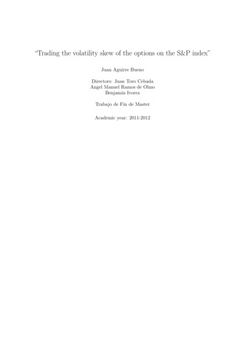
BEST EMBEDDED SYSTEM DEBUG 12 Vdc SupplyBuckDCDCMemory PowerBuckBuckDCDCDCDCPowerManagementIC (PMIC)BuckDCDCLDODCDCDRAM Memory(DDR, LPDDR)LDODCDCDRAM Memory(DDR, SKeyAnalog SignalPower RailPWM SignalDigital SignalSerial Data SignalParallel Data BusAnalog DeviceDigital DevicePower Conversion DeviceBuckDCDCSystem PowerBuckBuckDCDCDCDCBuckDCDCBoostDCDCPeripherals PowerBuckBuckBuckDCDCDCDCDCDCOscillatorLDODCDRAM (DDR)MemoryControlInterfaceI2CVSS VCOREPowerManagementInterface(I2C, PMbus,SMbus, SPMI)DCLDODCLDODCDCVCC-A VCC-PLL CKINDCCKOUT VCC-A12-bit ADCAnalog Sensor12-bit ADCAnalog SensorSPI or QSPII2CSmall LCDDriverSensor/ActuatorSPIControl DeviceSPIEmbedded SystemHigh-speed MCUSPIActuatorSPIShift Register2Audio OutputISInitializeResetTrigger In/OutPower ON ResetTimer/CounterInterruptPWM GPIOHigh-SpeedSerial Data1000Base-T1000Base-TPHYUARTFlexRayCAN FDUSB 2.0UARTPHYFlexRayPHYCAN FDPHYUSB 2.0PHYHigh-speedSerial PHYMixed Signal DeviceSerial Data PhyClock Analysis Capture long records to build statistics faster All-instance measurements measure every clockedge in any acquisition length Trend values over time Histicons show statistical distribution10
3.3 volt power rail at 5 mV/divPower Rail Analysis 12-bit resolution and low noise clearly shows smallsignal details in power rails FFT or Spectrum Analyzer determines root causeFFT of power rail to see frequency contentof high noise events Built-in high offset capability permits native probingof power railsProtocol Analysis Trigger on protocol elements or specific DATApatterns using powerful conditional DATA triggering Highly adaptable ERROR frame triggering isolatesprotocol errors Combine UART/SPI bytes into single “messageframe” to trigger on proprietary protocols Use Search and Zoom to correlate protocol eventsto other embedded signalsPower Analysis Measure and analyze operating characteristics ofpower conversion circuits Identify turn-on and turn-off transitions usingcolor-coded overlays Automatically calculate switching devicemeasurements Measure input/output power and input harmonics11
WAVESURFER 4000HD AT A GLANCE12435678Key Attributes1. 12.1” 1280 x 800 capacitivetouch screen display6. ProBus input supports over 30probes in 9 product categories9. WaveSource Arbitrary WaveformGenerator2. Buttons/indicators color-coded toassociated waveform on display7. Mixed Signal capability with 16channel dedicated digital logic port10. HDMI output3. MAUI with OneTouch user interfacefor intuitive and efficient operation8. USB 3.1 ports for easy connectivity 11. USBTMC over USB 2.0 for dataoffload4. HD4096 Technology - 12 bits allthe time5. Use cursors and adjust settingswithout opening a menu9101211
SPECIFICATIONSWaveSurfer 4024HDWaveSurfer 4034HDWaveSurfer 4054HDWaveSurfer 4104HD200 MHz1.75 ns350 MHz1 ns500 MHz700 ps1 GHz450 ps8.78.68.58.3Vertical - Analog ChannelsAnalog Bandwidth @ 50 Ω (-3 dB)Rise Time (10–90%)Input ChannelsVertical ResolutionEffective Number of Bits (ENOB)Vertical Noise Floor (rms, 50 Ω)1 mV/div2 mV/div5 mV/div10 mV/div20 mV/div50 mV/div100 mV/div200 mV/div500 mV/div1 V/divSensitivityDC Vertical Gain Accuracy(Gain Component of DC Accuracy)Channel-Channel IsolationOffset RangeDC Vertical Offset AccuracyMaximum Input VoltageInput CouplingInput ImpedanceBandwidth LimitersRescalingHorizontal - Analog ChannelsAcquisition ModesTimebasesTime/Division RangeClock AccuracyAcquisition - Analog ChannelsSample Rate (Single-Shot)Standard Memory (4 Ch / 2 Ch)Averaging412 bits65 μV70 μV90 μV65 μV70 μV90 μV65 μV70 μV90 μV70 μV75 μV95 μV95 μV95 μV115 μV160 μV175 μV210 μV270 μV290 μV350 μV960 μV925 μV1.10 mV1.60 mV1.75 mV2.10 mV2.70 mV2.90 mV3.50 mV50 Ω: 1 mV–1 V/div, fully variable; 1 MΩ: 1 mV–10 V/div, fully variable 0.5% FS, offset at 0 V60 dB60 dB up to 200 MHz50 dB up to 350 MHz125 μV125 μV125 μV130 μV160 μV280 μV465 μV1.65 mV2.75 mV4.70 mV60 dB up to 200 MHz50 dB up to 500 MHz60 dB up to 200 MHz50 dB up to 500 MHz40 dB up to 1 GHz50 Ω: 1 mV to 4.95 mV: 1.6 V; 5 mV to 9.9 mV: 4 V; 10 mV to 19.8 mV: 8 V; 20 mV to 1 V: 10 V1 MΩ: 1 mV to 4.95 mV: 1.6 V; 5 mV to 9.9 mV: 4 V; 10 mV to 19.8 mV: 8 V; 20 mV to 100 mV: 16 V;102 mV to 198 mV: 80 V; 200 mV to 1 V: 160 V; 1.02 V to 10 V: 400 V (1.0% of offset setting 0.5% FS 0.02% of max offset 1 mV)50 Ω: 5 Vrms, 1 MΩ: 400 V max (DC Peak AC 10 kHz)1 MΩ: AC, DC, GND; 50 Ω: DC, GND50 Ω: 2.0%; 1 MΩ: 2.0% 15 pF20 MHz20 MHz, 200 MHz20 MHz, 200 MHz20 MHz, 200 MHzElectrical: Volts, AmpsReal-time, Roll, Average, Sequence (Segmented Memory up to 1000 segments with 1 μs min. intersegment time)Internal timebase common to 4 input channels500 ps/div to 100 s/div 2.5 ppm 1.0 ppm/year from calibration2.5 GS/s on 4 Ch, 5 GS/s on 2 Ch12.5 Mpts / 25 MptsSummed averaging to 1024 sweepsVertical, Horizontal, Acquisition - Digital Channels (WS4KHD-MSO option only)Input ChannelsThreshold GroupingsThreshold SelectionsMaximum Input VoltageThreshold AccuracyInput Dynamic RangeMinimum Input Voltage SwingInput Impedance (Flying Leads)Maximum Input FrequencySample RateRecord LengthMinimum Detectable Pulse WidthChannel-to-Channel SkewUser-defined Threshold Range16 Digital ChannelsPod 2: D15 to D8, Pod 1: D7 to D0TTL ( 1.4 V), 5 V CMOS ( 2.5 V), ECL (-1.3 V) or User Defined 30 V Peak (3% of threshold setting 100 mV) 20 V500 mVpp100 kΩ 5 pF125 MHz500 MS/s12.5 Mpts - 16 Channels4 ns (1 digital sample interval) 10 V in 20 mV steps13
SPECIFICATIONSWaveSurfer 4024HDTriggering SystemModesSourcesCouplingHold-offPre-trigger DelayPost-trigger DelayInternal Trigger Level RangeExternal Trigger Level RangeMaximum Trigger RateTrigger Sensitivity with Edge Trigger(Ch 1–4)Trigger TypesWaveSurfer 4034HDWaveSurfer 4054HDWaveSurfer 4104HDNormal, Auto, Single, and StopAny input channel, Ext, Ext/5, or Line; slope and level unique to each source (except Line trigger)DC, AC, HFRej, LFRejFrom 10 ns up to 20 s or from 1 to 100,000,000 events0 to 100% of full scale0 to 10,000 divisions 4.1 div from center (typical)Ext ( 0.610 mV); Ext/5 ( 3.05 V)175,000 waveforms/second0.9 division @ 10 MHz0.9 division @ 10 MHz0.9 division @ 10 MHz0.9 division @ 10 MHz1.0 division @ 200 MHz1.0 division @ 350 MHz1.0 division @ 500 MHz1.0 division @ 1 GHzEdge, Width, Logic (Pattern), TV (NTSC, PAL, SECAM, HDTV - 720p, 1080i, 1080p), Runt, Slew Rate,Interval (Signal or Pattern), Dropout, Qualified (State or Edge). External input supports Edge trigger only.Low Speed Serial Protocol Triggering (Optional)I2C, SPI (SPI, SSPI, SIOP), UART-RS232, CAN1.1, CAN2.0, CAN FD, LIN, FlexRayMeasure, Zoom, and Math ToolsMeasurement ParametersZoomingMath FunctionsDisplay SystemSizeResolutionProbesStandard ProbesProbing SystemConnectivityEthernet PortRemovable StorageUSB Host PortsUSB Device PortExternal Monitor PortRemote ControlNetwork Communication StandardPower RequirementsVoltageNominal Power ConsumptionMax Power eSize and WeightDimensions (HWD)WeightCertificationsCE CertificationUL and cUL ListingWarranty and Service14Up to 6 parameters can be calculated at one time on any waveforms, selected from the following list ofmeasurements: Amplitude, Area, Base, Delay, Duty Cycle (50%, @level), Edge (@level), Fall Time (90%–10%),Fall Time (80%–20%), Frequency (50%, @level), Maximum, Mean, Minimum, Overshoot , Overshoot-, Peak-Peak,Period (50%, @level), Phase, Rise Time (10%–90%), Rise Time (20%–80%), RMS, Skew, Standard Deviation,ΔTime (@level) Top, ΔWidth (@level) Width , Width-. Statistics and histicons can be added to measurements.Measurements can be gated.Use front panel QuickZoom button, or Rectangle-Zoom using touch screen or mouse.Up to 2 math functions can be calculated at one time on any waveforms, selected from the following list ofoperations: Sum, Difference, Product, Ratio, Absolute Value, Average, Derivative, Enhanced Resolution, Envelope,Floor, Integral, Invert, Reciprocal, Rescale, Roof, SinX/x, Square, Square Root, Trend, Zoom and FFT (with PowerSpectrum output; Rectangular, VonHann and FlatTop windows).12.1" widescreen capacitive touch screen1280 x 800 pixelsPP019 (5 mm),PP026 (5 mm),1 per channel1 per channelBNC and Teledyne LeCroy ProBus for active voltage, current, and differential probes1 x 10/100BaseT Ethernet interface (RJ45 port)1 Micro SD port, 16 GB Micro SD card installed standard2 front USB 3.1 Gen1 ports, 2 back USB 2.0 ports1 USBTMC over USB 2.0 port1 HDMI port, supports up to 1280 x 800 pixelsMicrosoft COM Automation or LeCroy Remote Command SetVICP or VXI-11, LXI compatible100 to 240 VAC 10% @ 50 to 60 Hz 10%; 100 to 120 VAC 10% @ 400 Hz 5%; automatic AC voltage selection90 W / 90 VA150 W / 150 VAOperating: 0 C to 50 C; Non-operating: –30 C to 70 COperating: 5% to 90% RH (non-condensing) at 30 C, upper limit derates to 50% RH (non-condensing) at 50 C;Non-operating: 5% to 95% relative humidity (non-condensing) as tested per MIL-PRF-28800FOperating: 3,048 m (10,000 ft) max at 25 C; Non-operating: up to 12,192 meters (40,000 ft)10.7” H x 14.9” W x 6.3” D (273 mm x 380 mm x 160 mm)11.7 lbs (5.3 kg)CE compliant, UL and cUL listed; conforms to UL 61010-1 (3rd Edition), UL 61010-2-030 (1st Edition), andCAN/CSA C22.2 No. 61010-1-12 -year warranty; calibration recommended annually. Optional service programs include extended warranty,3upgrades, and calibration services.
SPECIFICATIONSWaveSurfer 4024HDWaveSurfer 4034HDWaveSurfer 4054HDWaveSurfer 4104HDDigital Voltmeter (Optional, available no charge at olutionMeasurement RateVertical Settings AutorangeACrms, DC, DCrms, FrequencyACV/DCV: 4 digits, Frequency: 5 digits100 times/second, measurements update on the display 5 times/secondAutomatic adjustment of vertical settings to maximize the dynamic range of measurementsWaveSource Arbitrary Waveform Generator (WS4KHD-FG option only)GeneralMax FrequencyChannelsSample RateArbitrary Waveform LengthFrequency ResolutionVertical ResolutionVertical RangeWaveform Types25 MHz1125 MS/s16 kpts1 μHz14 bits 3 V (HiZ); 1.5 V (50 Ω)Sine, Square, Triangle, Pulse, DC, Noise, ARB, Exponential Fall, Exponential Rise, Ramp, Gaussian, Lorentz, Cardiac,HaversineFrequency ularExponential Fall/RiseGaussian, Lorentz, CardiacNoiseResolutionAccuracyAging1 μHz - 25 MHz1 μHz - 10 MHz1 μHz - 300 KHz1 μHz - 1 MHz1 μHz - 5 MHz25 MHz (-3 dB)1 μHz 50 ppm, over temperature 3 ppm/year, first yearOutput SpecificationAmplitudeVertical AccuracyAmplitude Flatness4 mVpp - 6 Vpp ( HiZ); 2 mVpp - 3 Vpp (50 Ω) (0.3 dB 1 mV) 0.5 dBDC OffsetRange (DC)Offset Accuracy 3 V (HiZ); 1.5 V (50 Ω) (1% of offset value 3 mV)Waveform OutputImpedanceProtection50 Ω 2%Short-circuit protectionSine Spectrum PuritySFDR (Non Harmonic) @1.265 VppDC-1 MHz1 MHz - 5 MHz5 MHz - 25 MHzHarmonic Distortion @1.265 VppDC - 5 MHz5 MHz - 25 MHz-60 dBc-55 dBc-50 dBc-50 dBc-45 dBcSquare/PulseRise/Fall timeOvershootPulse WidthJitter24 ns (10% - 90%)3% (typical - 1 kHz, 1 Vpp)50 ns minimum500 ps 10 ppm of period (RMS cycle to cycle)Ramp/TriangleLinearitySymmetry0.1% of Peak value output (typical - 1 kHz, 1 Vpp, 100% symmetric)0% to 100%15
ORDERING INFORMATIONProduct DescriptionProduct CodeWaveSurfer 4000HD Oscilloscopes200 MHz, 2.5 GS/s, 4 Ch, 12.5 Mpts/ChHigh Definition Oscilloscopewith 12.1” capacitive touch screen350 MHz, 2.5 GS/s, 4 Ch, 12.5 Mpts/ChHigh Definition Oscilloscopewith 12.1” capacitive touch screen500 MHz, 2.5 GS/s, 4 Ch, 12.5 Mpts/ChHigh Definition Oscilloscopewith 12.1” capacitive touch screen1 GHz, 2.5 GS/s, 4 Ch, 12.5 Mpts/ChHigh Definition Oscilloscopewith 12.1” capacitive touch screenWaveSurfer 4024HDWaveSurfer 4034HDWaveSurfer 4054HDWaveSurfer 4104HDIncluded with Standard Configurations 10 passive probes (Qty. 4), Micro SD card (installed), Micro SD cardadapter, protective cover, Getting Started Guide, commercial NISTtraceable calibration with certificate, power cable for the destinationcountry, 3-year warrantyMulti-Instrument OptionsMixed-Signal Oscilloscope (incl. 16-channel digitalWS4KHD-MSOleadset, 22 extra large gripper probes, 20 groundextenders, 5 flexible ground leads and license)Spectrum Analyzer for WaveSurfer 4000HDWS4KHD-SPECTRUM-1WaveSource Arbitrary Waveform GeneratorWS4KHD-FGSerial Trigger and Decode OptionsAudioBus Trigger and DecodeAutomotive Bundle: CAN, CAN FD, LIN,FlexRay Trigger and DecodeEmbedded Bundle: I2C, SPI, UART-RS232Trigger and DecodePower Analysis OptionsPower AnalysisGeneral AccessoriesSoftcaseRackmount KitWS4KHD-AUDIO TDWS4KHD-AUTO TDWS4KHD-EMB TDWS4KHD-PWRWS4KHD-SOFTCASEWS4KHD-RACKBandwidth upgrades can be made at any time.Contact your local Teledyne LeCroy sales office.Product DescriptionProduct CodeProbes250 MHz Passive Probe – 5 mm, 10:1, 10 MΩPP019500 MHz Passive Probe – 5 mm, 10:1, 10 MΩPP0267.5 GHz Low Capacitance Passive Probe ( 10, 1 kΩ; 20, 500 Ω)PP066Power/Voltage Rail Probe with 4 GHz bandwidth,RP40301.2x attenuation, 30 V offset, 800 mVRP4030 Browser Tip AccessoryRP4000-BROWSER30 A, 50 MHz Current Probe –CP030AC/DC, 30 Arms,50 A peak pulse, 1.5-meter cable30 A, 10 MHz Current Probe –CP030-3MAC/DC, 30 Arms, 50 A peak pulse, 3-meter cable30 A, 50 MHz High Sensitivity Current Probe –CP030AAC/DC, 30 Arms, 50 A peak pulse, 1.5-meter cable30 A, 100 MHz Current Probe –CP031AC/DC, 30 Arms, 50 A peak pulse, 1.5-meter cable30A, 100 MHz High Sensitivity Current Probe –CP031AAC/DC, 30 Arms, 50 A peak pulse, 1.5-meter cable150 A, 10 MHz Current Probe –CP150AC/DC; 150 Arms; 500 A peak pulse, 2-meter cable150 A, 5 MHz Current Probe –CP150-6MAC/DC, 150 Arms, 500 A peak pulse, 6-meter cable500 A, 2 MHz Current Probe –CP500AC/DC, 500 Arms, 700 A peak pulse, 6-meter cableDeskew Calibration SourceDCS025700 V, 25 MHz High Voltage Differential Probe ( 10, 100)AP0311 kV, 25 MHz High Voltage Differential ProbeHVD3102A1 kV, 25 MHz High Voltage Differential ProbeHVD3102A-NOACC(without tip accessories)1 kV, 120 MHz High Voltage Differential ProbeHVD3106A1 kV, 80 MHz High Voltage Differential ProbeHVD3106A-6Mwith 6-meter Cable1 kV, 120 MHz High Voltage Differential ProbeHVD3106A-NOACC(without tip accessories)2 kV, 120 MHz High Voltage Differential ProbeHVD3206A2 kV, 80 MHz High Voltage Differential ProbeHVD3206A-6Mwith 6-meter Cable2kV, 400 MHz High Voltage Differential ProbeHVD32206 kV, 100 MHz High Voltage Differential ProbeHVD3605AHigh Voltage Fiber Optic Probe, 150 MHz bandwidthHVFO108HVFO100 Universal 1 V Tip AccessoryHVFO100-1X-TIP-UHVFO100 Universal 5 V Tip AccessoryHVFO100-5X-TIP-UHVFO100 Universal 10 V Tip AccessoryHVFO100-10X-TIP-UHVFO100 Universal 20 V Tip AccessoryHVFO100-20X-TIP-UHVFO100 Universal 40 V Tip AccessoryHVFO100-40X-TIP-U100:1 400 MHz 50 MΩ 1 kV High Voltage ProbeHVP120PPE6KV-A2 kV HV Probe, 6 kV overvoltage capability500 MHz, 60 V Common Mode Differential Probe.DL05-HCMIncludes standard set of leads and tips.1 GHz, 60 V Common Mode Differential Probe.DL10-HCMIncludes standard set of leads and tips.200 MHz, 3.5 pF, 1 MΩ Active Differential Probe, 20 VZD200500 MHz, 1.0 pF Active Differential Probe, 8 VZD500500 MHz Active Differential Probe ( 1, 10, 100)AP0331 GHz, 1.0 pF Active Differential Probe, 8 VZD10001.5 GHz, 1.0 pF Active Differential Probe, 8 VZD15001 GHz, 0.9 pF, 1 MΩ High Impedance Active ProbeZS10001.5 GHz, 0.9 pF, 1 MΩ High Impedance Active ProbeZS1500Probe AdaptersTek Probe to ProBus Probe Adapter1-800-5-LeCroyteledynelecroy.comTPA10Local sales offices are located throughout the world.Visit our website to find the most convenient location. 2022 by Teledyne LeCroy, Inc. All rights reserved. Specifications, prices, availability, and delivery subject to change without notice.Product or brand names are trademarks or requested trademarks of their respective holders.wavesurfer4000hd-ds-11jul22
7 Spectrum Analyzer Spectrum analyzer style controls Logarithmic scales op up Peaks and Markers tableP Built-in Waveform Generator Frequencies of up to 25 MHz ariety of Wide v waveform sources available Saved waveforms can be uploaded to oscilloscope to generate arbitrary waveforms DVM and Frequency Counter 4-digit digital voltmeter, 5-digit frequency counter