Transcription
XPDR/DMETCAS/ADS-B/TISTest SetIFR 6015Getting Started ManualEXPORT CONTROL WARNING: This document contains controlled technical data under thejurisdiction of the Export Administration Regulations (EAR), 15 CFR 730-774. It cannot betransferred to any foreign third party without the specific prior approval of the U.S. Department ofCommerce, Bureau of Industry and Security (BIS). Violations of these regulations are punishableby fine, imprisonment, or both.
GETTING STARTED MANUALXPDR/TACAN/TCAS/ADS-B/TISTEST SETIFR 6015PUBLISHED BYAeroflexCOPYRIGHT Aeroflex 2016All rights reserved. No part of this publication may be reproduced, stored in a retrieval system, ort r a n s m i t t e d i n a n y f o r m o r b y a n y m e a n s , e l e c t r o n i c , m e c h a n i c a l , p h o t o c o p y i n g , r e c o r d i n g o r o t h e r wi s ewi t h o u t t h e p r i o r p e r m i s s i o n o f t h e p u b l i s h e r .Original PrintingJan 2010Issue 1Mar 2015Issue 2Nov 201610200 W est York / W ichita, Kansas 67215 U.S.A. / (316) 522-4981 / FAX (316) 524-2623Subject to Export Control, see Cover Page for details.
GETTING STARTED MANUALIFR 6015THIS PAGE INTENTIONALLY LEFT BLANK.Subject to Export Control, see Cover Page for details.
GETTING STARTED MANUALIFR 6015Product WarrantyRefer to http://ats.aeroflex.com/warranty for the Product Warranty information.Electromagnetic CompatibilityD o u b l e s h i e l d e d a n d p r o p e r l y t e r m i n a t e d e xt e r n a l i n t e r f a c e c a b l e s m u s t b e u s e d wi t h t h i s e q u i p m e n twh e n i n t e r f a c i n g wi t h t h e R E M O T E C o n n e c t o r . F o r c o n t i n u e d E M C c o m p l i a n c e , a l l e xt e r n a l c a b l e s m u s tbe shielded and 3 meters or less in length.Nomenclature StatementI n t h i s m a n u a l , 6 0 1 5 , T e s t S e t o r U n i t r e f e r s t o t h e I F R 6 0 1 5 XP D R / T A C A N / T C A S / A D S - B / T I S T e s t S e t .Declaration of ConformityT h e D e c l a r a t i o n o f C o n f o r m i t y C e r t i f i c a t e i n c l u d e d wi t h t h e U n i t s h o u l d r e m a i n wi t h t h e U n i t . A e r o f l e xrecommends the operator reproduce a copy of the Declaration of Conformity Certificate to be storedwi t h t h e O p e r a t i o n M a n u a l f o r f u t u r e r e f e r e n c e .Software VersionA e r o f l e x u p d a t e s T e s t S e t s o f t wa r e o n a r o u t i n e b a s i s . A s a r e s u l t , e xa m p l e s m a y s h o w i m a g e s f r o me a r l i e r s o f t wa r e v e r s i o n s . I m a g e s a r e u p d a t e d wh e n a p p r o p r i a t e .C o m p l yi n g w i t h I n s t r u c t i o n sThe safety precautions in this manual must be observed during installation and operation. Aeroflexa s s u m e s n o l i a b i l i t y f o r f a i l u r e t o c o m p l y wi t h a n y s a f e t y p r e c a u t i o n o u t l i n e d i n t h i s m a n u a l .Subject to Export Control, see Cover Page for details.
GETTING STARTED MANUALIFR 6015THIS PAGE INTENTIONALLY LEFT BLANK.Subject to Export Control, see Cover Page for details.
GETTING STARTED MANUALIFR 6015SAFET Y FIRST : T O ALL O PERAT IO NS PERSO NNELR E F E R AL L S E R V I C I N G O F U N I T T O Q U AL I F I E D T E C H N I C AL P E R S O N N E L . T H I S U N I T C O N T AI N SN O O P E R AT O R S E R V I C E AB L E P AR T S .W AR N I N G : U S I N G T H I S E Q U I P M E N T I N A M AN N E R N O T S P E C I F I E D B Y T H E AC C O M P AN Y I N GD O C U M E N T AT I O N M AY I M P AI R T H E S AF E T Y P R O T E C T I O N P R O V I D E D B Y T H EEQUIPM ENT.C AS E , C O V E R O R P AN E L R E M O V ALO p e n i n g t h e C a s e A s s e m b l y e xp o s e s t h e o p e r a t o r t o e l e c t r i c a l h a z a r d s t h a t c a n r e s u l t i n e l e c t r i c a ls h o c k o r e q u i p m e n t d a m a g e . D o n o t o p e r a t e t h e I F R 6 0 1 5 wi t h t h e C a s e A s s e m b l y o p e n .S AF E T Y I D E N T I F I C AT I O N I N T E C H N I C AL M AN U ALT h i s m a n u a l u s e s t h e f o l l o wi n g t e r m s t o d r a w a t t e n t i o n t o p o s s i b l e s a f e t y h a z a r d s t h a t m a y e xi s t wh e noperating or servicing this equipment.C AU T I O N :THIS TERM IDENTIFIES CONDITIONS OR ACTIVITIES THAT, IF IGNORED, CAN RESULTIN EQUIPMENT OR PROPERTY DAMAGE (E.G., FIRE).W AR N I N G : T H I S T E R M I D E N T I F I E S C O N D I T I O N S O R AC T I V I T I E S T H AT , I F I G N O R E D , C AN R E S U L TI N P E R S O N AL I N J U R Y O R D E AT H .S AF E T Y S Y M B O L S I N M AN U AL S AN D O N U N I T SC AU T I O N : R e f e r t o a c c o m p a n y i n g d o c u m e n t s . ( T h i s s y m b o l r e f e r s t os p e c i f i c C A U T I O N S r e p r e s e n t e d o n t h e u n i t a n d c l a r i f i e d i n t h e t e xt . )AC O R D C T E R M I N AL : T e r m i n a l t h a t m a y s u p p l y o r b e s u p p l i e d wi t h A C o rDC voltage.D C T E R M I N AL : T e r m i n a l t h a t m a y s u p p l y o r b e s u p p l i e d wi t h D C v o l t a g e .AC T E R M I N AL : T e r m i n a l t h a t m a y s u p p l y o r b e s u p p l i e d wi t h A C o ralternating voltage.E Q U I P M E N T G R O U N D I N G P R E C AU T I O NImproper grounding of equipment can result in electrical shock.USE OF PROBESC h e c k t h e s p e c i f i c a t i o n s f o r t h e m a xi m u m v o l t a g e , c u r r e n t a n d p o we r r a t i n g s o f a n y c o n n e c t o r o n t h eI F R 6 0 1 5 b e f o r e c o n n e c t i n g i t wi t h a p r o b e f r o m a t e r m i n a l d e v i c e . B e s u r e t h e t e r m i n a l d e v i c ep e r f o r m s wi t h i n t h e s e s p e c i f i c a t i o n s b e f o r e u s i n g i t f o r m e a s u r e m e n t , t o p r e v e n t e l e c t r i c a l s h o c k o rdamage to the equipment.POWER CORDSP o we r c o r d s m u s t n o t b e f r a y e d , b r o k e n n o r e xp o s e b a r e wi r i n g wh e n o p e r a t i n g t h i s e q u i p m e n t .Subject to Export Control, see Cover Page for details.
GETTING STARTED MANUALIFR 6015SAFET Y FIRST : T O ALL O PERAT IO NS PERSO NNEL ( cont )USE RECOMMENDED FUSES ONLYUse only fuses specifically recommended for the equipment at the specified current and voltage ratings.I N T E R N AL B AT T E R YThis unit contains a Lithium Ion Battery, serviceable only by a qualified technician.C AU T I O N :SIGNAL GENERATORS CAN BE A SOURCE OF ELECTROMAGNETIC INTERFERENCE(EMI) TO COMMUNICATION RECEIVERS. SOME TRANSMITTED SIGNALS CAN CAUSEDISRUPTION AND INTERFERENCE TO COMMUNICATION SERVICES OUT TO A DISTANCEOF SEVERAL MILES. USERS OF THIS EQUIPMENT SHOULD SCRUTINIZE ANYOPERATION THAT RESULTS IN RADIATION OF A SIGNAL (DIRECTLY OR INDIRECTLY)AND SHOULD TAKE NECESSARY PRECAUTIONS TO AVOID POTENTIALCOMMUNICATION INTERFERENCE PROBLEMS.Subject to Export Control, see Cover Page for details.
GETTING STARTED MANUALIFR 6015T ABLE O F CO NT ENT SS e r vi c e U p o n R e c e i p t o f Ma t e r i a l2Specifications5Installation6Controls, Connectors and Indicators9A u xi l i a r y E q u i p m e n t13Screen Hierarchy15S e l f Te s t20B a t t e r y/ V o l t a g e I n s t r u c t i o n s24Fuse Replacement28Battery Replacement29Subject to Export Control, see Cover Page for details.Page 1Nov 1/16
GETTING STARTED MANUALIFR 6015SERVICE UPO N RECEIPT O F M AT ERIALU N P AC K I N GS p e c i a l - d e s i g n p a c k i n g m a t e r i a l i n s i d e t h i s s h i p p i n g c a r t o n p r o v i d e s m a xi m u m p r o t e c t i o n f o r t h eIFR 6015. Avoid damaging the carton and packing material during equipment unpacking. Use thef o l l o wi n g s t e p s f o r u n p a c k i n g t h e I F R 6 0 1 5 .lCut and remove the sealing tape on the carton top and open the carton.lG r a s p t h e I F R 6 0 1 5 t r a n s i t c a s e f i r m l y , wh i l e r e s t r a i n i n g t h e s h i p p i n g c a r t o n , a n d l i f t t h e e q u i p m e n tand packing material vertically.lPlace the IFR 6015 transit case and end cap packing on a suitable flat, clean and dry surface.lRemove the protective plastic bag from the IFR 6015 transit case. Place the desiccant bags backinside the protective plastic bag.lPlace protective plastic bag and end cap packing material inside shipping carton.lStore the shipping carton for future use should the IFR 6015 need to be returned.Subject to Export Control, see Cover Page for details.Page 2Nov 1/16
GETTING STARTED MANUALIFR 6015SERVICE UPO N RECEIPT O F M AT ERIAL ( cont )C H E C K I N G U N P AC K E D E Q U I P M E N TlInspect the equipment for damage incurred during shipment. If the equipment has been damaged,r e p o r t t h e d a m a g e t o A e r o f l e x.lCheck the equipment against the packing slip to see if the shipment is complete. Report alld i s c r e p a n c i e s t o A e r o f l e x.P AR T N U M B E RQTYIFR 6015DESCRIPTION724241POW ER SUPPLY673661ANTENNA917711BREAKOUT BOX645801ANTENNA SHIELD6474911 2 I N . C O A XI A L C A B L E6240117 2 I N . C O A XI A L C A B L E11283015 A FUSE560801TRANSIT CASE102411POW ER CORD (US ONLY)623021POW ER CORD (EUROPEAN)640201OPERATION MANUAL (CD-ROM)60971GETTING STARTED MANUAL (PAPER)61001I F R 6 0 1 5 wi t h S t a n d a r d A c c e s s o r i e sSubject to Export Control, see Cover Page for details.Page 3Nov 1/16
GETTING STARTED MANUALIFR 6015SERVICE UPO N RECEIPT O F M AT ERIAL ( co n t )C H E C K I N G U N P AC K E D E Q U I P M E N T ( c o n t )O P T I O N AL AC C E S S O R I E SP AR T N U M B E RQTYDesk Top Stand636561Tripod674741Tripod, Dolly, Stand8255312 5 f t T N C / T N C C O A XI A L C A B L E6246215 0 f t T N C / T N C C O A XI A L C A B L E863361UC-584 Dual Antenna Coupler Kit1123491UC-584 Single Antenna Coupler Kit11235011 2 I N . C O A XI A L C A B L E ( G P S )11283117 2 I N . C o a xi a l C A B L E ( G P S )112837160951IFR-6000 Maintenance Manual-(CD-ROM)Antenna Coupler and CableSubject to Export Control, see Cover Page for details.Page 4Nov 1/16
GETTING STARTED MANUALIFR 6015S P E C I F I C AT I O N SInput Power (IFR 6015):Input Range:11 to 32 VdcP o we r C o n s u m p t i o n :5 5 W M a xi m u m1 6 W N o m i n a l a t 1 8 V d c wi t h c h a r g e d b a t t e r yFuse Requirements:5 A, 32 Vdc, Type FI n p u t P o w e r ( S u p p l i e d E x t e r n a l AC t o D C C o n ve r t e r ) :Input Range:1 0 0 t o 2 5 0 V A C , 1 . 5 A M a x, 4 7 t o 6 3 H zMains Supply Voltage Fluctuations: 10% of the nominal voltageTransient Overvoltages:According to Installation Category IIE n vi r o n m e n t a l ( I F R 6 0 1 5 ) :Use:Pollution Degree 2Altitude: 4800 mOperating Temperature:-20 C to 55 C(Battery charging temperature range is 5 to 40 Ccontrolled by internal charger)Storage Temperature:-30 C to 71 C(Li Ion Battery must be removed below -20 C and above60 C.)Relative Humidity:95% ( 5%) from 5 to 30 C75% ( 5%) from 30 to 40 C45% ( 5%) from 40 to 55 CE n vi r o n m e n t a l ( S u p p l i e d E x t e r n a l AC t o D C C o n ve r t e r ) :Use:IndoorsAltitude: 10,000 mOperating Temperature:0 C to 40 CStorage Temperature:-20 C to 71 CSubject to Export Control, see Cover Page for details.Page 5Nov 1/16
GETTING STARTED MANUALIFR 6015INST ALLAT IO NG E N E R ALT h e I F R 6 0 1 5 i s p o we r e d b y a n i n t e r n a l L i t h i u m I o n b a t t e r y p a c k . T h e I F R 6 0 1 5 i s s u p p l i e d wi t h a ne xt e r n a l D C P o we r S u p p l y t h a t e n a b l e s t h e o p e r a t o r t o r e c h a r g e t h e b a t t e r y wh e n c o n n e c t e d t o A Cp o we r .NOTE:T h e I F R 6 0 1 5 c a n o p e r a t e c o n t i n u o u s l y o n A C p o we r v i a t h e D C P o we r S u p p l y , f o r s e r v i c i n gand/or bench tests.B AT T E R Y O P E R AT I O NT h e i n t e r n a l b a t t e r y i s e q u i p p e d t o p o we r t h e I F R 6 0 1 5 f o r m o r e t h a n f o u r h o u r s o f c o n t i n u o u s u s e ,a f t e r wh i c h t i m e , t h e I F R 6 0 1 5 b a t t e r y n e e d s r e c h a r g i n g . B a t t e r y O p e r a t i o n T i m e R e m a i n i n g ( i n H o u r s )is displayed on all screens.T h e I F R 6 0 1 5 c o n t a i n s a n a u t o m a t i c t i m e - o u t t o c o n s e r v e p o we r . I f a k e y i s n o t p r e s s e d wi t h i n a 5 t o2 0 m i n u t e t i m e p e r i o d , t h e I F R 6 0 1 5 s h u t s O f f ( o n l y wh e n u s i n g b a t t e r y p o we r ) . T h e P o we r D o wn T i m emay be set in the Setup Screen.B AT T E R Y C H AR G I N GT h e b a t t e r y c h a r g e r o p e r a t e s wh e n e v e r D C p o we r ( 1 1 t o 3 2 V d c ) i s a p p l i e d t o t h e I F R 6 0 1 5 wi t h t h es u p p l i e d D C P o we r S u p p l y o r a s u i t a b l e D C p o we r s o u r c e . W h e n c h a r g i n g , t h e b a t t e r y r e a c h e s a 1 0 0 %c h a r g e i n a p p r o xi m a t e l y f o u r h o u r s . T h e i n t e r n a l b a t t e r y c h a r g e r a l l o ws t h e b a t t e r y t o c h a r g e b e t we e na t e m p e r a t u r e r a n g e o f 5 t o 4 0 C . T h e I F R 6 0 1 5 c a n o p e r a t e , c o n n e c t e d t o a n e xt e r n a l D C s o u r c e ,outside the battery charging temperature range (5 C to 40 C).The battery should be charged every three months (minimum) or disconnected for long term inactives t o r a g e p e r i o d s o f m o r e t h a n s i x m o n t h s . T h e B a t t e r y m u s t b e r e m o v e d wh e n c o n d i t i o n s s u r r o u n d i n gthe IFR 6015 are -20 C and 60 C)S AF E T Y P R E C AU T I O N ST h e f o l l o wi n g s a f e t y p r e c a u t i o n s m u s t b e o b s e r v e d d u r i n g i n s t a l l a t i o n a n d o p e r a t i o n . A e r o f l e x a s s u m e sn o l i a b i l i t y f o r f a i l u r e t o c o m p l y wi t h a n y s a f e t y p r e c a u t i o n o u t l i n e d i n t h i s m a n u a l .C o m p l yi n g w i t h I n s t r u c t i o n sI n s t a l l a t i o n / o p e r a t i n g p e r s o n n e l s h o u l d n o t a t t e m p t t o i n s t a l l o r o p e r a t e t h e I F R 6 0 1 5 wi t h o u t r e a d i n ga n d c o m p l y i n g wi t h i n s t r u c t i o n s c o n t a i n e d i n t h i s m a n u a l . A l l p r o c e d u r e s c o n t a i n e d i n t h i s m a n u a l m u s tb e p e r f o r m e d i n e xa c t s e q u e n c e a n d m a n n e r d e s c r i b e d .Grounding Power CordW AR N I N G :D O N O T U S E A T H R E E - P R O N G T O T W O - P R O N G AD AP T E R P L U G . D O I N G S O C R E AT E SA S H O C K H AZ AR D B E T W E E N T H E C H AS S I S AN D E L E C T R I C AL G R O U N D .F o r A C o p e r a t i o n , t h e A C L i n e C a b l e , c o n n e c t e d t o t h e D C P o we r S u p p l y , i s e q u i p p e d wi t h s t a n d a r dthree-prong plug and m ust be connected to a properly grounded three-prong receptacle that is easilyaccessible. It is the customer's responsibility to:lHave a qualified electrician check receptacle(s) for proper grounding.lR e p l a c e a n y s t a n d a r d t wo - p r o n g r e c e p t a c l e ( s ) wi t h p r o p e r l y g r o u n d e d t h r e e - p r o n g r e c e p t a c l e ( s ) .Subject to Export Control, see Cover Page for details.Page 6Nov 1/16
GETTING STARTED MANUALIFR 6015INST AL L AT IO N ( co n t )Operating SafetyD u e t o p o t e n t i a l f o r e l e c t r i c a l s h o c k wi t h i n t h e I F R 6 0 1 5 , t h e C a s e A s s e m b l y m u s t b e c l o s e d wh e n t h eI F R 6 0 1 5 i s c o n n e c t e d t o a n e xt e r n a l p o we r s o u r c e .Battery replacement, fuse replacement and internal adjustments must only be performed by qualifiedservice technicians.AC P O W E R R E Q U I R E M E N T ST h e D C P o we r S u p p l y , s u p p l i e d wi t h t h e I F R 6 0 1 5 , o p e r a t e s o v e r a v o l t a g e r a n g e o f 1 0 0 t o 2 5 0 V A C a t47 to 63 Hz.T h e b a t t e r y c h a r g e r o p e r a t e s wh e n e v e r D C p o we r ( 1 1 t o 3 2 V d c ) i s a p p l i e d t o t h e I F R 6 0 1 5 wi t h t h es u p p l i e d D C P o we r S u p p l y o r a s u i t a b l e D C p o we r s o u r c e . W h e n c h a r g i n g , t h e b a t t e r y r e a c h e s a n1 0 0 % c h a r g e i n a p p r o xi m a t e l y f o u r h o u r s . T h e B a t t e r y C h a r g i n g t e m p e r a t u r e r a n g e i s 5 C t o 4 0 C ,controlled by an internal battery charger.B AT T E R Y R E C H AR G I N GSTEP1.PROCEDUREConnect AC Line Cable to either:lA C P W R C o n n e c t o r o n t h e D C P o we r S u p p l y a n d a n a p p r o p r i a t e A C p o we r s o u r c elS u i t a b l e D C p o we r s o u r c e2.C o n n e c t t h e D C P o we r S u p p l y t o t h e D C P O W E R C o n n e c t o r o n t h e I F R 6 0 1 5 .3.V e r i f y t h e C H A R G E I n d i c a t o r i l l u m i n a t e s y e l l o w.4.Allow four hours for battery charge or until the CHARGE Indicator illuminates green.NOTE:If the CHARGE Indicator flashes yellow and/or the battery fails to accept a charge andt h e I F R 6 0 1 5 d o e s n o t o p e r a t e o n b a t t e r y p o we r , t h e b a t t e r y , s e r v i c e a b l e o n l y b y aqualified technician, requires replacement. Refer to Battery/Voltage Instructions.Subject to Export Control, see Cover Page for details.Page 7Nov 1/16
GETTING STARTED MANUALIFR 6015INST AL L AT IO N ( co n t )E X T E R N AL C L E AN I N GT h e f o l l o wi n g p r o c e d u r e c o n t a i n s r o u t i n e i n s t r u c t i o n s f o r c l e a n i n g t h e o u t s i d e o f t h e I F R 6 0 1 5 .C AU T I O N :STEPDISCONNECT POW ER FROM IFR 6015 TO AVOID POSSIBLE DAMAGE TO ELECTRONICCIRCUITS.PROCEDURE1.C l e a n f r o n t p a n e l b u t t o n s a n d d i s p l a y f a c e wi t h s o f t l i n t - f r e e c l o t h . I f d i r t i s d i f f i c u l t t o r e m o v e ,d a m p e n c l o t h wi t h wa t e r a n d a m i l d l i q u i d d e t e r g e n t .2.R e m o v e g r e a s e , f u n g u s a n d g r o u n d - i n d i r t f r o m s u r f a c e s wi t h s o f t l i n t - f r e e c l o t h d a m p e n e d ( n o ts o a k e d ) wi t h i s o p r o p y l a l c o h o l .3.R e m o v e d u s t a n d d i r t f r o m c o n n e c t o r s wi t h s o f t - b r i s t l e d b r u s h .4.C o v e r c o n n e c t o r s , n o t i n u s e , wi t h s u i t a b l e d u s t c o v e r t o p r e v e n t t a r n i s h i n g o f c o n n e c t o rcontacts.5.C l e a n c a b l e s wi t h s o f t l i n t - f r e e c l o t h .6.P a i n t e xp o s e d m e t a l s u r f a c e t o a v o i d c o r r o s i o n .Subject to Export Control, see Cover Page for details.Page 8Nov 1/16
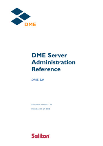
GETTING STARTED MANUALIFR 6015CO NT RO LS, CO NNECT O RS AND INDICAT O RSRF I/OVIDEOSYNCANTREMOTEREMOTEIFR 6015TCASXPDRSETUPTACANTACANINTERRREPLYFREQRF LVLRANGERATEDISPLAYCTRSPOWER CHARGEBKLT05804Subject to Export Control, see Cover Page for .35.36.37.38.39.40.SYNC ConnectorVIDEO ConnectorDC POW ER ConnectorRF I/O ConnectorANT ConnectorREMOTE ConnectorDisplayMulti-Function Soft KeysXP D R M o d e S e l e c t K e yTCAS Mode Select KeyTACAN Mode Select KeySETUP Select KeyFREQ Select KeyRF LVL KeyRATE INCREMENT KeyRANGE INCREMENT KeyRATE DECREMENT KeyRANGE DECREMENT KeyBACKLIGHT KeyPOW ER KeyHARGE IndicatorPOW ER IndicatorINTERR IndicatorREPLY IndicatorCONTRAST KeyDECREMENT/SELECT Data KeySELECT DATA UNIT MSB KeySELECT DATA UNIT LSB KeyINCREMENT/SELECT Data KeyANT ConnectorAUX OUT Connector 1AUX OUT Connector 2AUX OUT Connector 3AUX OUT Connector 4USB HOST ConnectorUSB DEVICE ConnectorAltitude Encoder ConnectorAUX IN ConnectorRS-232 ConnectorREMOTE ConnectorPage 9Nov 1/16
GETTING STARTED MANUALIFR 6015CO NT RO LS, CO NNECT O RS AND INDICAT O RS ( cont )ITEM1.DESCRIPTIONSYNC ConnectorBNC type connector provides oscilloscope SYNC pulse for each interrogation.2.VIDEO ConnectorBNC type connector provides interrogation and reply pulses.3.DC POWER ConnectorCircular Type Connector (2.5 mm center, 5.5 mm outer diameter, center positive) used for batterycharging or operation of the IFR 6015.4.RF I/O ConnectorTNC Type connector used for direct connection to UUT antenna connector.5.AN T C o n n e c t o rTNC Type Connector used for connection to the IFR 6015 directional antenna for over the airtesting.6.REM OTE ConnectorT y p e H D D B 4 4 C o n n e c t o r u s e d f o r r e m o t e o p e r a t i o n a n d s o f t wa r e u p g r a d e s . C o n t a i n s R S - 2 3 2 ,USB Host and USB Peripheral connections (altitude encoder inputs and SYNC outputs).7.Display (LCD)3 8 c h a r a c t e r s b y 1 6 l i n e s f o r m a i n s c r e e n d i s p l a y wi t h S o f t K e y b o xe s a t t h e b o t t o m o f t h escreen.8.M u l t i - F u n c t i o n S o f t K e ysF i v e A p p l i c a t i o n d e p e n d e n t k e y s p r o v i d e t e s t s p e c i f i c i n f o r m a t i o n a n d m o v e m e n t b e t we e n t e s ts c r e e n s . T h e l e g e n d s a r e d i s p l a y e d i n b o xe s a t t h e b o t t o m o f t h e D i s p l a y .9.XPDR MODE Select Key10.T C AS M O D E S e l e c t K e ySelects Transponder Auto Test Screen.Selects TCAS Auto Test Screen.11.T AC AN M O D E S e l e c t K e y12.SETUP Key13.FREQ Select Key14.RF LVL KeySelects TACAN Test Screen.Displays the SETUP Menu.Selects DME Frequency as VOR Paired, TACAN Channel or MHz.TACAN mode function only. Selects TACAN range reply and squitter RF level.15.R AT E I N C R E M E N T K e yIncrements TACAN or TCAS range rate.Subject to Export Control, see Cover Page for details.Page 9Nov 1/16
GETTING STARTED MANUALIFR 6015CO NT RO LS, CO NNECT O RS AND INDICAT O RS ( cont )ITEMDESCRIPTION16.R AN G E I N C R E M E N T K e y17.R AT E D E C R E M E N T K e y18.R AN G E D E C R E M E N T K e yIncrements TACAN or TCAS range.Decrements TACAN or TCAS range rate.Decrements TACAN or TCAS range.19.B AC K L I G H T K e yD i s p l a y s / e xi t s t h e B a c k l i g h t A d j u s t F i e l d .20.POWER KeyP o we r s t h e I F R 6 0 1 5 O N a n d O F F .21.C H AR G E I n d i c a t o r22.POWER Indicator23.INTERR IndicatorI l l u m i n a t e d wh e n e xt e r n a l D C p o we r i s a p p l i e d f o r B e n c h O p e r a t i o n o r B a t t e r y c h a r g i n g .I l l u m i n a t e d wh e n t h e I F R 6 0 1 5 i s o p e r a t i o n a l .I l l u m i n a t e d wh e n t h e I F R 6 0 1 5 i s g e n e r a t i n g a n i n t e r r o g a t i o n s i g n a l ( XP D R M o d e ) o r r e c e i v e s a nInterrogation (TCAS Mode) signal.24.REPLY IndicatorI l l u m i n a t e d wh e n t h e I F R 6 0 1 5 r e c e i v e s a v a l i d r e p l y s i g n a l ( XP D R M o d e ) o r g e n e r a t e s a r e p l y(TCAS Mode) signal.25.C O N T R AS T K e yD i s p l a y s / e xi t s t h e C o n t r a s t A d j u s t F i e l d .26.DECREMENT SELECT Data KeyD e c r e m e n t s d a t a i n s l e wa b l e f i e l d s , s u c h a s R F L V L . T h i s K e y a l s o s e l e c t s d a t a i n f i e l d s t h a th a v e f i xe d f u n c t i o n s , s u c h a s E C H O a n d S Q U I T T E R .27.S E L E C T D AT A U N I T M S B K e yM o v e s t h e s l e w c u r s o r t o wa r d t h e M S B ( M o s t S i g n i f i c a n t B i t ) o f t h e d a t a f i e l d .28.S E L E C T D AT A U N I T L S B K e yT h i s K e y m o v e s t h e s l e w c u r s o r t o wa r d t h e L S B ( L e a s t S i g n i f i c a n t B i t ) o f t h e d a t a f i e l d .29.INCREM ENT/SELECT Data KeyI n c r e m e n t s d a t a i n s l e wa b l e f i e l d s , s u c h a s R F L V L . T h i s K e y a l s o s e l e c t s d a t a i n f i e l d s t h a th a v e f i xe d f u n c t i o n s , s u c h a s E C H O a n d S Q U I T T E R .30.AN T C o n n e c t o r31.AU X O U T C o n n e c t o r 1TNC Type Connector used for connection to the IFR 6015 for over the air testing.ATCRBS interrogation trigger used for calibration.Subject to Export Control, see Cover Page for details.Page 10Nov 1/16
GETTING STARTED MANUALIFR 6015CO NT RO LS, CO NNECT O RS AND INDICAT O RS ( cont )ITEMDESCRIPTION32.AU X O U T C o n n e c t o r 233.AU X O U T C o n n e c t o r 3ATCRBS interrogation trigger used for calibration.Not Used34.AU X O U T C o n n e c t o r 4Not Used35.USB HOST Connector 4U S B J u m p D r i v e i n t e r f a c e f o r s o f t wa r e u p d a t e a n d t e s t d a t a d u m p ( n o t a c t i v e i n f i r s t r e l e a s e ) .36.USB DEVICE ConnectorRemote Control Interface.37.AL T I T U D E E N C O D E R C o n n e c t o rI n t e r f a c e f o r e xt e r n a l e n c o d i n g a l t i m e t e r .38.AU X I N C o n n e c t o r39.RS-232 ConnectorNot UsedU s e d f o r r e m o t e c o n t r o l i n t e r f a c e , s o f t wa r e u p d a t e a n d t e s t d a t a d u m p .40.REM OTE ConnectorU s e d t o i n t e r f a c e wi t h t h e I F R 6 0 1 5 .Subject to Export Control, see Cover Page for details.Page 11Nov 1/16
GETTING STARTED MANUALIFR 6015AUXIL IARY EQ UIPM ENTD I R E C T I O N AL AN T E N N AThe Directional Antenna may be used mounted directly on the IFR 6015, hand held or mounted on atripod.Position Directional Antenna in direct sight of UUT antenna, avoiding close obstructions such asgantries, ladders and tool chests etc.Distance for testing top UUT antenna should be sufficient so UUT antenna is visible. Distance fortesting bottom UUT antenna should be close enough so that top UUT antenna is not visible. SuppliedA n t e n n a S h i e l d s h o u l d b e m o u n t e d o n b o t t o m U U T a n t e n n a t o a v o i d u n wa n t e d r e p l i e s .Subject to Export Control, see Cover Page for details.Page 12Nov 1/16
GETTING STARTED MANUALIFR 6015AUXIL IARY EQ UIPM ENT ( co n t )B R E AK O U T B O XThe Breakout Box accessory provides access to individual user interfaces via standard connectors).T h e I F R 6 0 1 5 R e m o t e C o n n e c t o r p r o v i d e s t h e m a i n u s e r s i g n a l i n t e r f a c e f o r t h e B r e a k o u t B o x.The Breakout Box attaches to the IFR 6015 via a remote connector located on the top of the IFR 6015a n d t h u m b s c r e ws o n t h e b a c k .Subject to Export Control, see Cover Page for details.Page 13Nov 1/16
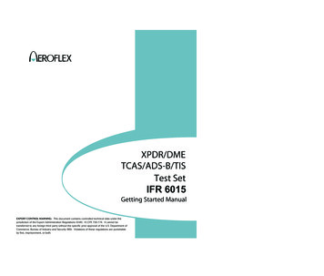
GETTING STARTED MANUALIFR 6015SCREEN HIERARCHYT h e XP D R A U T O T E S T S c r e e n a l wa y s a p p e a r s o n P o we r - U p .XPDR-AUTO TESTBATP AS SCONFIG:MK12/S-M4ANTENNA: BOTTOM2.5 HrLEVEL 4REPLIES 1,2,3A,C,SFREQ 1090.12 MHZTOP ERP 57.1 dBmMTL -74.0 dBmMTL -73.1 dBmBOT ERP 56.0 dBm3A CODE 1234C ALT 35000ft1 CODE 12342 CODE 1234T AIL N12345DF17 DETECTED NOFLT ID AA-50AA AC3421(53032041)FS 5–NO AL ERTSPIIN AIRVS IN AIRCOUNTRY United StatesRUNTESTTESTLISTCONFIGSELECTANTT h e S E T U P M e n u a l l o ws t h e o p e r a t o r t o s e t v a r i o u s p a r a m e t e r s u s e d i n t e s t i n g , c o n f i g u r a t i o n a n dm e m o r y s t o r a g e . P r e s s t h e S E T U P K e y t o d i s p l a y t h e XP D R S e t u p S c r e e n , p r e s s a g a i n f o r t h e T A C A NSetup Screen, again for General Setup Screen.BATSETUP-XPDRANTENNA: BOTTOMTOP:BOTTOM:RF PORT:ANTENNAANT RANGE50.0m50.0 mDIR CABLE LOSS:1.3 dBANT CABLE:6 FTANT CABLE LOSS:1.7 dBUUT ADDRESS:AUTOMANUAL AA:123456DIVERSITY TEST:ONPREVPARAM2.5 HrNEXTPARAM2.5 HrRF PORT: ANTENNAANT RANGE : 10 ftANT HEIGHT10.0 m0.0 mANT GAIN (dBi)1.03 GHz: 7.11.09 GHz: 6.1PWR LIM: FAR 43CHECK CAP: YESDIAGBATSET UP–T ACANTESTDATAIDENT TONE : AERODIR CABLE LOSS:1.2 dBANT CABLE : 1 FTANT CABLE LOSS :0.1 dBMAX RANGE: 400.00 nmTEST MODE: 5-VARIABLESYNC:MRBPREVPARAMANT GAIN (dbI)0.96 GHz :7.51.03 GHz :7.11.09 GHz :6.11.15 GHz :5.01.22 GHz :2.8NEXTPARAMSubject to Export Control, see Cover Page for details.DIAGBATSETUP – GENERALPWRDOWN : 10 minsERPUNITS : dBmREMOTE2.5 HrUNITS : METERSOPERATION : RS232PREVPARAMNEXTPARAMH/WTOOLSINFOPage 14Nov 1/16
GETTING STARTED MANUALIFR 6015SCREEN HIERARCHY ( co n t )T h e XP D R A U T O T E S T S c r e e n i s t h e o p e n i n g s c r e e n . T h e s c r e e n s a r e c h a n g e d b y p r e s s i n g t h e XP D RMode Key or an application specific Soft Key.Screen OrganizationXPDR AUTO TESTXPDR ALT ENCODERXPDR CONFIGXPDR TEST LISTSelected ConfigurationSelected TestT h e XP D R A u t o T e s t S c r e e n i s t h e p r i m a r y t e s t s c r e e n . W h e n a M o d e S c o n f i g u r a t i o n i s s e l e c t e d t h et e s t l i s t i s d i s p l a y e d o v e r t wo s c r e e n s a n d A T C R B S c o n f i g u r a t i o n s d i s p l a y t h e t e s t l i s t o n o n e s c r e e n .XPDR-AUTO TESTP AS SBATCONFIG:GENERIC MODE SANTENNA: BOTTOM2.5 HrLEVEL 4REPL IES 3 A, C, SFREQ 1090.12 MHZTOP ERP 57.1 dBmMTL -74.0 dBmBOT ERP 56.0 dBmMTL -73.1 dBm3A CODE 1234C ALT 35000ftS CODE 1234S ALT 35000ftT AIL N12345DF17 DETECTED NOFLT ID AA-50AA AC3421(53032041)FS 5–NO AL ERTSPIIN AIRVS IN AIRCOUNTRY United StatesRUNTESTTESTLISTSubject to Export Control, see Cover Page for details.CONFIGSELECTANTPage 15Nov 1/16
GETTING STARTED MANUALIFR 6015SCREEN HIERARCHY ( co n t )P r e s s t h e T e s t L i s t S o f t K e y t o a c c e s s 1 7 a d d i t i o n a l XP D R T e s t S c r e e n s .S Al l C a l l T e s t S c r e e nA/ C D e c o d e r / S L S T e s t S c r e e nXPDR– 3 A/ C DECDR/SL SBATP AS SDECODER INNER LOWDECODER INNER HIGHDECODER OUTER LOWDECODER OUTER HIGHSLS0 dBSLS -9 dBC ALT 100000 ftA4 A2 A1 B4 B2B1 C4RUNTESTC2D4C1PREVTESTD4F1 WIDTH 3A 0.300 usF2 WIDTH3A 0. 00 usF1-F23A 20.300 usRUNTESTRETURNC 128.07 usC 0.510 usC 2AC421C 100%C 0%PREVTESTNEXTTESTRETURNS Reply Timing Test ScreenBAT2.5 HrXPDR–S RPLY TIMINGC 0. 50 us C 0.600 usC 20.300 us3A PASS3A 128.08 us3A 0.510 us3A 2AC4213A 100%3A 0%2.5 HrMODE S ALL-CALL PASSADDRESS 2AC421TAIL N12345COUNTRY United StatesREPLY DELAY3A 3.05 us C 3.55 usREPLY JITTER3A 0.250 usC 0.000 usREPLY RATIO3A 100%C 100%-81dBm REPLY RATIO3A 0%C 0%ATCRBS ALL-CALLBATP AS SD2NEXTTESTF AI LALL-CALLITM REPLYDELAYJITTERADDRESSRATIO-81dBmD1 XD2A/ C S p a c i n g W i d t h T e s t S c r e e nXPDR– 3 A/ C SPAC/ WDT HXPDR–SC PASSC PASSC PASSC PASSC PASSC PASS3A PASS3A PASS3A PASS3A PASS3A PASS3A PASS3A CODE 2620
In this manual, 6015, Test Set or Unit refers to the IFR 6015 XPDR/TACAN/TCAS/ADS-B/TIS Test Set. Declaration of Conformity . The Declaration of Conformity Certificate included with the Unit should remain with the Unit. Aeroflex recommends the operator reproduce a copy of the Declaration of Conformity Certificate to be stored