Transcription
8" and 10" T4 Series In-Wall TouchscreenInstallation GuideSupported models C4-T4IW8-BL8" T4 In-Wall Touchscreen, Black C4-T4IW8-WH8" T4 In-Wall Touchscreen, White C4-T4IW10-BL10" T4 In-Wall Touchscreen, Black C4-T4IW10-WH10" T4 In-Wall Touchscreen, WhiteIntroductionThe Control4 T4 Series 8- and 10-inch In-Wall Touchscreens offercomplete system control in an elegant and compact design. Thetouchscreens are equipped with a full capacitive screen, audioand video Intercom (with the built-in camera) using SIP, andmore.This touchscreen works great in either new construction orretrofit installations. For power and network connectivity, choosefrom three options: Ethernet with PoE—The Ethernet network connection isprovided through the PoE Injector. No additional wiring isneeded. WiFi with PoE—The internal Wi-Fi will communicate with theLAN’s wireless AP, so no additional network wiring is needed.PoE power is used to power the touchscreen.Note: 802.11b is not recommended for video intercom.We recommend using Wireless-N. See “Specifications”and “Power and Network Installation Options” for moreinformation.Box contents 8" or 10" T4 In-Wall Touchscreen Power box (to power the touchscreen) Two screws (to attach the power box to the wall box) Set screw (to secure the touchscreen to the power box) Set screw tool (3/32" straight-shaft hex driver)1Accessories available for purchase Pakedge 802.3at/af Gigabit PoE Injector (PI-30AT), orAraknis Networks Gigabit PoE Injector(AN-ACC-INJ-POE-30W), each sold separately. Wall box options (sold separately)—Metal and plastic, fornew construction or retrofit installations. In-Wall Touchscreen Wall Box Kits - New Construction Plastic (C4-NWB57C-P) Metal (C4-NWB57C-M) In-Wall Touchscreen Wall Box Kits - Retrofit Plastic (C4-RWB57C-P) Metal (C4-RWB57C-M)For wall box installation details, see: In-Wall Touchscreen Wall Box Installation Guide-NewConstruction (ctrl4.co/wallbox-new) In-Wall Touchscreen Wall Box Installation Guide-Retrofit(ctrl4.co/wallbox-retro)
WarningsWarning! Do not place the touchscreen near sources ofheat or expose to direct sunlight for an extended periodof time.AVERTISSEMENT ! Ne placez pas l’unité près dessources de chaleur ou exposition pour diriger la lumièredu soleil pendant une période prolongée.Specifications and requirementsSpecificationsModel NumbersC4-T4IW10-BL, C4-T4IW10-WH,C4-T4IW8-BL, C4-T4IW8-WHScreenResolution: 1920 1200, capacitive touchCamera: 720pNetworkEthernet or Wi-Fi 802.11b/g/n 2.4 GHz 802.11a/n/ac 5 GHz Security: WEP, WPA/WPA2 PSK, 802.1x EAP, PEAPNotes: (1) While technically the touchscreen canuse 802.11b, 802.11b is not supported. (2) 802.11nis recommended for best performance. Evenwith 802.11n, broadcasting to several devices willdegrade Video Intercom response time and images.Broadcasting to additional devices will furtherdegrade performance. See “Wireless NetworkLimitations.”Power supplyPoE (IEEE 802.3af) 13 W peakDimensions (W H D)8” model: 202 142 15 mm (8.0 5.6 0.59”)10" model: 239 165 13 mm (9.4 6.5 0.53")Wall box: 68 104 61 mm (2.7 4.1 2.4")Power box: 71 114 46 mm (2.8 4.5 1.8")Weight (with mid-box)8" model: 0.41 kg (0.9 lb)10" model: 0.68 kg (1.5 lb)Operating temperature0 to 40 C (32 to 104 F)Storage temperature-20 to 70 C (-4 to 158 F)Warning! Install in accordance with all national, state,and local electrical codes.AVERTISSEMENT ! Installez selon tous les national, état,et codes électriques locaux.Warning! This product generates heat. The room musthave adequate ventilation or the ability to dissipate heateffectively.AVERTISSEMENT ! Ce produit produit de la chaleur.La salle doit avoir à ventilation proportionnée ou lacapacité d’absorber la chaleur efficacement.Warning! Use this product only in dry locations.AVERTISSEMENT ! Employez ce produit seulement dansdes endroits secs.Caution! Do not use pens or sharp objects to navigateor make selections on the touchscreen. To select an itemor scroll through a list, use your fingertip.AVERTISSEMENT ! N’employez pas les stylos ou lesobjets pointus pour diriger ou pour faire des choix surl’écran. Pour choisir un article ou un rouleau par uneliste, employez votre bout du doigt.Caution! Improper use or installation can causeDAMAGE OF PROPERTY.AVERTISSEMENT ! L’utilisation ou l’installation inexactepeut causer DAMAGE DE PROPRIÉTÉ.Important! Using this product in a manner other thanoutlined in this document voids your warranty. Further,Control4 is NOT liable for any damage incurred with themisuse of this product. See “Warranty.”Important ! Utilisant ce produit en quelque sorte autreque décrit dans ce document vide votre garantie. Deplus, Control4 n’est pas responsable d’aucun dommageencouru avec l’abus de ce produit. Voyez que «Warranty. »Requirements A controller fully installed and configured with Control4OS 3.2.1 or later. Control4 Touchscreen wall box installed. See “Accessories.” If using Ethernet with PoE power: Ethernet network installed and available that includes agateway/router/switch Control4 PoE Injector (model #AC-POE1-B) or anotherthird-party, UL/ANSI-certified PoE injector or switch. Two Ethernet Cat 5/6 cables: (1) one that runs from theEthernet gateway/router/switch to the PoE injector/switchand (2) one that runs from the PoE injector/switch to theEthernet connection in the touchscreen’s wall box. If using Wi-Fi with a PoE injector: Wireless network (IEEE 802.11b/g/n) installed andavailable with a wireless access point (AP). Security canbe WEP, WPA/WPA2 PSK, 801.1x EAP, or PEAP.2
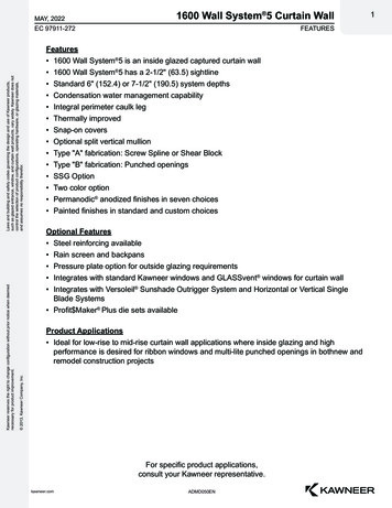
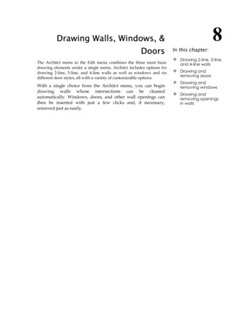
Front viewTop viewAB CLM NL Power button. Press to turn the display on and off, press andhold to select Power off or Restart, or press and hold for 10seconds to reset the device.M Center pinhole. Not used.N Reset pinhole. Press to reset, or press and hold until “Erasing”appears on the screen to restore factory defaults.DETouchscreen placementPlace the touchscreen in a convenient location at eye level,typically near the entrance of the room, about 145 to 155 cm(57 to 61 inches) from the floor (Figure 3).ABCDEAmbient light sensorCameraIndicator LED (startup, camera in use, audio listening)Stereo microphones8" or 10" diagonal, capacitive 1920 1200 displayNote: Consider the camera on the panel and the heightof the people in the home who will use the camera forVideo Intercom.Important: The top of the touchscreen must bemounted no higher than 2 m (6.6 ft.) above the floor.Figure 1: Touchscreen placementBack viewTouchscreenF GPower source forPoE injectorLED indicatorHIJKF Upper mount tabG Power—Press this button to turn the touchscreen on, or pressand hold it to turn the touchscreen off.H Docking electrical connectorI Locking tabJ Set screw—secures the touchscreen to the power box.K Stereo speakers3The LED on the touchscreen indicates the camera status of thecamera and booting information as described in the next table.Camera/LED color stateTouchscreen statusOffCamera is offGreenCamera is onGreen (momentary blink)Touchscreen is bootingInstallationImportant! Before you can complete the instructionsbelow, you must have an 8" or 10" Touchscreen wall boxinstalled according to the documentation provided inthe wall box kit. See “Accessories” for details.Important ! Avant de lire les instruction ci-dessous,il vous faut un support mural installé suivant ladocumentation fournie avec le kit du support mural. Plusde détails dans la partie Accessoires .Important! When cutting the opening for the wall box,do not cut the opening too large. Be conservative andcautiously enlarge it as needed.Important ! En coupant l’ouverture pour le supportmural, ne faites pas une ouverture trop grande. Soyezprudent, et agrandissez la avec précaution.
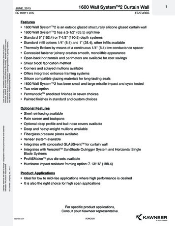
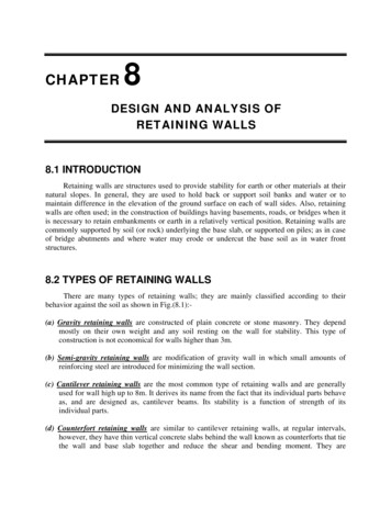
Power and network installation optionsThis device uses an Ethernet or Wi-Fi network connection andcan be powered using PoE.Figure 2: Ethernet with PoE—Requires Ethernet connection to PoEinjectorPlace touchcreen hereChoose one of the following options to install the power andnetwork communication.Option 1: Ethernet connection with PoEPoE supplies DC power on the Ethernet cable using a PoEInjector (model #AC-POE1-B) or a third-party PoE solution toprovide the touchscreen with power and a network connection.The touchscreen works with the Control4 PoE Injector or a thirdparty PoE Injector.Wi-FiPoEinjectorWirelessaccess pointControllerSwitchTo set up your PoE and Ethernet connection with a PoE Injector:1 Attach the PoE Injector according to the instructions in yourPoE’s installation guide if provided. Control4 PoE Injectorinstructions are provided later in this document.2 Pull the Ethernet cable from that location to where you wantto install the touchscreen.Figure 2: Ethernet with PoE—Requires Ethernet connection to PoEinjectorPower installationPrepare the plastic power box for installation into the wall box byinserting the Ethernet cable into the power box, and then followthe instructions below.Connecting PoEConnect the PoE injector to power and the network, and thenconnect it to the power box. It can be located anywhere alongthe cable that connects the power box to the network switch.To install a Control4 PoE injector:1 Connect the Control4 PoE injector to an AC outlet using thepower cord.2 Connect one of the LAN ports on the network switch to thePoE Injector’s LAN port using Cat 5/6 Ethernet cable.3 Pull a cable going from the PoE injector’s PWR LAN-OUTport through one of the touchscreen’s left-side wall boxknockout holes.4 Go to “Connecting to a wired network” below.Option 2: Wi-Fi with PoE injectorConnecting to a wired networkA PoE injector supplies DC power to the touchscreen via anEthernet cable. The touchscreen works with the Control4 PoEInjector or any compatible third-party PoE Injector.To connect to a wired network:To set up your Wi-Fi connection and a PoE injector:1 Attach the PoE Injector according to the instructions in yourPoE’s installation guide, if provided. Control4 PoE Injectorinstructions are provided later in this document.2 Pull the Ethernet cable from that location to where you wantto install the touchscreen.41 Pull the in-wall Ethernet cable through a left-side knockouthole of the wall box, then plug it into the Ethernet jack onthe back of the power box (Figure 8).Figure 5: Insert Ethernet cable into power box
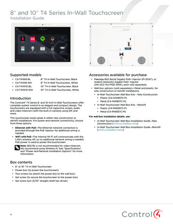
Note: The Ethernet port on the power box does nothave functioning indicator LEDs.2 Go to “Attach the power box and touchscreen” below.Attach the power box and touchscreenTo attach the power box and touchscreen:1 Align and bend the wires to fit them inside the wall box.2 Slide the power box into the wall box, then secure thepower box to the wall box using the two screws provided(Figure 6).Caution: Do not use an electric driver to tighten the screws.Overtightening can result in the power box becoming slightlywarped, resulting in a poor electrical docking connection.Use only a hand screwdriver to tighten the screws.Tip: If overtightened screws result in the power box warping,loosen the screws until the power box is flush to the wall.Figure 7: Secure power box to wall boxConfigurationConfigure the touchscreen for wireless (optional)To configure the touchscreen for wireless:1 After initialization, tap Network. The network configurationpage opens.2 Under Wi-Fi, make sure the Wi-Fi is enabled, then tap theWi-Fi field to open a list of available networks.3 Tap the network name you want to connect to.4 Tap the Password field, then use the on-screen keyboard totype the password (if required).Note: If you need to enter a static IP address, follow theinstructions under “To set a wireless static IP address”below before proceeding.5 Tap Connect.If you don’t see the network you want:1 Tap , then tap the Network SSID field and type the SSID(name) of the network by using the on-screen keyboard.2 Tap the Security field, then select the type of security to use.3 Tap the Password field, then use the on-screen keyboard totype the password (if required).Note: If you need to enter a static IP address, follow theinstructions under “To set a wireless static IP address”below before proceeding.4 Tap Save. The new network is added to the bottom of thenetwork list.To set a wireless static IP address:3 Angle the top of the touchscreen toward the wall, insert thetop mounting bracket onto the power box, then press thebottom of the touchscreen into place (a magnet will hold itin position).Figure 8: Attach the touchscreen top first1 Scroll down and tap Show advanced options.2 Tap IP settings, then tap Static.3 Select each box one at a time and use the on-screenkeyboard to type the: IP address Gateway Network prefix length DNS 1 (preferred) DNS 2 (alternate)Configure the touchscreen for EthernetIf you want to use DHCP (default) for your Ethernet connection,no further setup is required.To configure a static IP address for Ethernet:1 After initialization, tap Network. The network configurationpage opens.2 Tap Ethernet. The Ethernet settings screen opens.3 Tap Static IP Settings, then tap Use static IP.4 Secure in place with the included set screw and 3/32"straight-shaft hex driver.4 Select each box one at a time and use the on-screenkeyboard to type the IP Address, Gateway, Netmask, DNS 1(preferred), and DNS 2 (alternate).5 Tap SAVE when finished.5
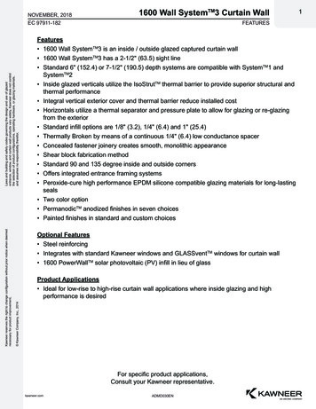
Add and configure in Composer ProTroubleshootingAfter the touchscreen is installed and appears on the homenetwork, use Composer Pro to add it to the Control4 system andconfigure it.Boot up timeUse the Composer Pro System Design and Connections views toadd and configure this device.To add and configure a T4 touchscreen to a project:1 Add the T4 8/10" In-Wall Touchscreen driver to your project.Unresponsive screen2 Select the touchscreen or its Intercom component in theproject tree’s System Design view.If the logo image does not appear after 30 seconds, the devicemay need to be power cycled. If power cycling doesn’t solve theproblem, the touchscreen may need to be restored to factorydefaults.3 View and change the properties in the Properties pane asneeded.Properties include: Network Connection—Reports the touchscreen’s currentnetwork connection type. Back Light—Use the arrows or type numbers to set thelight level, then click Set. Adaptive Brightness Enabled—Enables or disablesadaptive brightness.Advanced properties include: Camera Enabled—Enables or disables the camera. Reboot—Remotely reboots the touchscreen.Intercom properties (nested under the touchscreen): Appearance Exclude from Navigator—Select to hide thetouchscreen from appearing in user interfaces as anavailable device. High Quality Enabled—Select to use the highestresolution setting for the camera. Dial Pad UI Enabled—Enables the on-screen dial pad. Behavior Select the modes you want this touchscreen tosupport: Play Door Chime, Do Not Disturb, AutoAnswer, Send Video, Monitor Mode, Echo Calibration,Disable Echo Cancellation. Audio Control—Select the volume of individual audiosettings. Sip Information—Information for integrating thetouchscreen into your SIP/VoIP system. Custom Buttons—Select to enable and label the twoavailable custom buttons Alternate Camera—Select to use an external camera forthe video associated with the touchscreen, for example,a security camera mounted to the side of the personoperating the touchscreen.6When the device is booting up, it may take 10 seconds before thelogo image appears on the screen. When it turns on, you will seean image for a short time, then it will turn off. After that, eitherthe setup menu or the room’s home screen will appear.To manually power-cycle the touchscreen:1 Press and hold the power button for at least 10 seconds untilthe touchscreen turns off.To restore to factory defaults:1 On the touchscreen’s main screen, tap Settings, System Info,then Factory data reset.- OR If the touchscreen has not yet been configured, tap About,then Factory data reset.- OR To restore defaults without using the displayscreen, press and hold the reset pinhole buttonuntil “Erasing” appears on the screen.Removing the touchscreen from the wallTo remove the touchscreen:1 Remove the 3/32" set screw.2 Pull the bottom of the touchscreen away from the lockingtab, then lift the screen up and off the power box.Figure 9: Lift bottom away and lift up
Additional resourcesThe following resources are available for additional support. Knowledgebase and forums in Technician Community Technical Support Control4 website: www.control4.com Composer documentation in its online help.Warranty and legal noticesFind details of this product’s 2-Year Limited Warranty atsnapav.com/warranty, or request a paper copy from CustomerService at (866) 424-4489. Find other legal resources, such asregulatory notices and patent information, at snapav.com/legal.More helpFor the latest version of this document, open this URL or scanthe QR code on a device that can view PDFs.LATEST VERSION OF THIS DOCUMENTctrl4.co/t4-inwall-ig7WALL BOX INSTALL: NEW CONSTRUCTIONWALL BOX INSTALL: RETROFITctrl4.co/wallbox-newctrl4.co/wallbox-retro
control4.com 888.400.4070Copyright 2020, Wirepath Home Systems, LLC. All rights reserved. Control4 and Snap AV and their respective logos are registered trademarks or trademarks ofWirepath Home Systems, LLC, dba “Control4” and/or dba “SnapAV” in the United States and/or other countries. Snap AV and Wirepath are also registered trademarksor trademarks of Wirepath Home Systems, LLC. Other names and brands may be claimed as the property of their respective owners. All specifications subject to changewithout notice.200-00678-C.22020-11-16 MSC
the cable that connects the power box to the network switch. To install a Control4 PoE injector: 1 Connect the Control4 PoE injector to an AC outlet using the power cord. 2 Connect one of the LAN ports on the network switch to the PoE Injector's LAN port using Cat 5/6 Ethernet cable. 3 Pull a cable going from the PoE injector's PWR LAN-OUT