Transcription
Advent XT2Assisted Living Call Management Systemascom VoWiFiInstallation Manuali62Tynetec operates a policy of continual product improvement andreserves the right to modify the specification of its products.If any variation to the details in this document are suspected pleasecontact Tynetec’s Technical Support.Tynetec, a business unit of Legrand Electric LtdCowley Road, Blyth Riverside Business Park, Blyth, Northumberland, NE24 5TF.T: 44 (0) 1670 352 371 www.tynetec.co.ukTrusted TechnologyCaring for PeopleDoc No. FM0855 issue 2
2324TopicProduct OverviewImportant Safety InstructionsRegulatory InformationMaintenance & CareVoWiFi OverviewRelated DocumentationSite Wiring RequirementsAscom i62 VoWiFi Handset & ChargerMatrix NENX IP-PBXDraytek Vigor AP 903 Access PointMesh Access Point InstallationVoWiFi System Installation OverviewLaptop Setup for Draytek DevicesCheck & Upgrade Draytek FirmwareMesh Root SetupMesh Node SetupMesh Node DiscoveryMesh Node DeploymentVoWiFi System CommissioningSpecification: Ascom i62 VoWiFi HandsetSpecification: Ascom i62 Charger & PSUSpecification: Matrix NENX IP-PBXSpecification: Draytek Vigor AP 903 Access PointAmendments Doc No. FM0855 issue 2 Page 2
1. PRODUCT OVERVIEWThe ascom VoWiFi system provides a reliable Voice Over IP communication solution that combines theopen standard for wireless radio networks and SIP telephony technologies. Utilizing the IEEE 802.11nstandard for wireless LAN (WLAN) communications, the ascom VoWiFi system provides the benefits ofincreased speed, improved reliability and extended range of wireless transmissions.The ascom VoWiFi system allows 2-way voice communications with residents via the Advent XT2 wardencall system and between staff, both internally and externally if required.When the Advent XT2 is operating in onsite mode all alarm calls are reported via the VoWiFi system.When the phone rings the caller will be identified on the display (provided the phone book memory isprogrammed), when answered a voice message will announce the call type and channel ID before a speechlink is opened.The ascom VoWiFi system comprises of 2 elements;1. a bundled package including a Matrix IP-PBX, 2 x i62 VoWiFi handsets c/w chargers and PSU’s2. a maximum of 8 x Draytek Vigor AP 903 Mesh Access PointsThe Matrix IP-PBX is preconfigured so both CO analogue trunks ring all SLT and IP extensions, it also has itsDHCP server enabled. Both ascom i62 handsets have their WiFi settings and SIP credentials preconfiguredas extensions 151 and 152. A maximum of 5 IP extensions (151 to 155 are possible). The Matrix IP-PBXallows the VoWiFi handsets to integrate with the Advent XT2 warden call system, it also allows access to anoutside line to make/receive external telephone calls and VoWiFi handset-handset calling.One Mesh Access Point (known as the Mesh Root) is always hardwired to the Matrix IP-PBX Ethernet portvia a standard UTP Cat5e patch lead, max length 100 metres. Up to a maximum of 7 more Mesh AccessPoints (known as Mesh Nodes) can be deployed wirelessly around the building to achieve site-wide WiFicoverage. Each Mesh Access Point requires connection to a local mains supply using the plug-top mainsadapter supplied. If it’s not possible to power the Mesh Access Points from a local mains supply then theycan be powered from an auxiliary 12V DC power supply, but additional site wiring will be required. TheMesh Root supports PoE on LAN Port A1, but an additional PoE switch or PoE injector will be required.The size/complexity of the building will determine the total number of Mesh Access Points needed toachieve site-wide coverage. The exact positioning of the Mesh Access Points will be determined by a sitesurvey prior to commencing the installation. A free Draytek Wireless App is available to simplify the setupof the mesh network; 3Doc No. FM0855 issue 2 Page 3
2. SAFETY INSTRUCTIONSRead and understand these instructions before use. Refer to the Manufacturers installation and userguides for more information (see section 6 of this manual). Keep all instructions for future reference.Take care when working on step ladders during installation or service.Isolate the mains supply before removing covers.Do not disassemble any part of the system or attempt to repair it yourself.No user serviceable parts inside. Refer all servicing to qualified service personnel.PSU’s should only be connected to a 220-240VAC 50/60Hz mains supply.If you are unsure of the type of power supply consult your local power company.Danger of explosion if rechargeable batteries are incorrectly replaced.Use only Manufacturer approved batteries as specified in this manual.Only use Manufacturer approved cable during installation.See section 7 of this manual for details of cable type and cable length restrictions.Mesh Access Points should be located at least 5 metres away from any other electronic equipment.Failure to provide this separation may result in reduced radio range.Do not locate Mesh Access Points above a radiator or other heat source.Do not expose Mesh Access Points to direct sunlight.Do not submerge Mesh Access Points in water and do not use in damp or humid conditions.Do not drop or expose Mesh Access Points to high vibration or shock.Do not expose Mesh Access Points to dripping or splashing water.Liquids can cause a failure and/or a fire hazard.Clean VoWiFi handsets with a damp cloth and a non-abrasive cleaning product.Polish with a dry duster. DO NOT submerge in water or use a wet cloth.Avoid using harsh, abrasive or corrosive cleaning agents or detergents (e.g. scouring powders,bleaches, polishes, etc.) when cleaning VoWiFi handsets.At their end of life VoWiFi products should be disposed of and recycled in accordance with theenvironmental regulations. See the Regulatory Information in section 3 of this manual.Doc No. FM0855 issue 2 Page 4
3. REGULATORY INFORMATIONThis symbol on the product indicates it complies with all relevant EU Directives as required by law e.g.Radio & Telecommunication Terminal Equipment (RTT&E), Safety of Information TechnologyEquipment (LVD), Electro Magnetic Compatibility (EMC) and Restriction of Hazardous Substances RoHS.See the Specification for each individual product in section 20 onwards for relevant Approvals.A copy of the complete Declaration of Conformity is available from Tynetec.This symbol on the product indicates it is classed as Electrical or Electronic Equipment and should notbe disposed of with other commercial waste at the end of its working life.The Waste of Electrical and Electronic Equipment (WEEE) Directive (2012/19/EU) has been put in placeto recycle products using the best available recovery and recycling techniques to minimise impact onthe environment, treat hazardous substances and avoid increasing landfill.For product disposal please contact your supplier and check the terms and conditions of the purchasecontract and ensure this product is not mixed with other commercial waste for disposal.This symbol on batteries indicates separate collection. Batteries contain chemicals that can behazardous to health and the environment and should not be disposed of in the waste bin.The EU Directive (2006/6/EC) has been put in place to ensure the safe disposal and recycling ofbatteries.Return used batteries to your supplier or drop-off at your local municipal waste recycling depot.NTENTS4. MAINTENANCE & CAREFor peace of mind and to ensure your system is maintained to the highest standard Tynetec recommend anannual Maintenance Contract. This will provide vital assistance in times of need from a nationwide team oftrained Service Engineers who specialise in warden call systems.A Preventative Maintenance Visit (PMV) is also recommended, this covers the replacement of all batteries,a full system test, software updates (where applicable) and a Service Certificate.For more information on Maintenance Contract packages and PMV’s please contact your local TynetecApproved Installer, a list can be found on our website; www.tynetec.co.uk/installer-locatorMONTHLY MAINTENANCEThe Matrix IP-PBX and Draytek Vigor VP 903 Access Points do not require any regular maintenance, if anyitems show signs of damage they should be replaced immediately by a Service Engineer.Products needing repair can be returned via the website; www.tynetec.co.uk/returns-policyANNUAL MAINTENANCEThe rechargeable battery in the VoWiFi handsets should be replaced typically every 2 years or 500 chargingcycles. See the specification for the i62 handset in section 20 for details of battery type.In the unlikely event that the VoWiFi system needs to be turned-off or reset, please ensureall active calls are actioned before proceeding.Doc No. FM0855 issue 2 Page 5
5. VoWiFi OVERVIEWThe maximum theoretical range for any VoWiFi system is 300 feet (92 metres) outdoors under idealconditions, in practice this range will rarely be reached due to reflections from nearby buildings, trees,water, etc.Obstructions inside buildings such as walls and floors will reduce the range, some construction materialssuch as foil backed plasterboard, reinforced concrete or stone walls will reduce range further.Environmental conditions such as high levels of transmission at nearby frequencies or emissions from otherelectrical equipment may also reduce range.Clear line-of-sight will give maximum radio coverage, it is impossible to state a specific indoor range inadvance of a site survey; however, as a guide you can usually achieve 150 feet (46 metres) radius from eachMesh Access Point.Locating the Mesh Access Point as high and free from immediate obstruction as possible will help tomaximise its range. Even if the Access Point is placed in the optimum position it may not always achievecoverage in the most remote corners, if this is the case then additional Access Points will be required.The Mesh Access Points should always be located at least 5 metres away from the Advent XT2 controller,NTR’s or any other electrical equipment to avoid the risk of interference.Mesh Access Points must be sited in a dry secure area; they are NOT suitable for outdoor locations.AVOID LOCATING MESH ACCESS POINTS WITHIN 5 METRES OFOTHER ELECTRONICEQUIPMENTDIRECTLY ABOVE AHEAT SOURCEIN DIRECT SUNLIGHTNEAR TO SPLASHINGWATERIMPORTANT NOTE:Care must be taken during installation and commissioning of any VoWiFi system to ensure full coverageand correct Mesh Access Point setup. Failure to follow the Manufacturer’s installation and programminginstructions may result in blind spots or calls dropping-out when moving between Mesh Nodes. Alwaysperform several test calls in all extremes of the building with both VoWiFi handsets in use.SDoc No. FM0855 issue 2 Page 6
6. RELATED DOCUMENTATIONThis manual provides general information regarding the installation of Ascom VoWiFi handsets with theMatrix IP-PBX and Draytek Mesh Access Points.For more detailed information refer to the Ascom and Draytek installation and user guides.ASCOM DOCUMENTSYou can request copies of the documents listed below from Tynetec’s customer support. Quick Reference Guide for Ascom i62 VoWiFi HandsetUser Manual for Ascom i62 VoWiFi HandsetConfiguration Manual for Ascom i62 VoWiFi HandsetDRAYTEK DOCUMENTSYou can request copies of the documents listed below from Tynetec’s customer support. Quick Start Guide for Draytek Vigor AP 903 Mesh Access PointUser Guide for Draytek Vigor AP 903 Mesh Access PointDoc No. FM0855 issue 2 Page 7
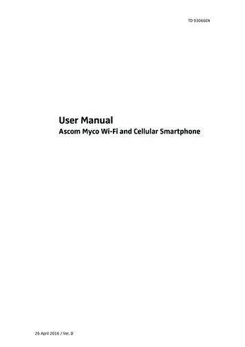
7. SITE WIRING REQUIREMENTSASCOM VoWiFi SYSTEMLAN BLAN A4LAN A3LAN A2ABCDE FGH IJKLMNOQRTUVXYLAN A15G2.4GLAN BLAN BLAN A4LAN A4LAN A3LAN A3LAN A2LAN A2LAN A1LAN A15G5G2.4G2.4GUSBUSBACTACTascomPACTZSWUSBETHERNET EXTENSIONIf the Mesh Root Access Point needs to be located in a remote locationwhere the 2m UTP Patch lead provided isn’t long enough to reach theMatrix IP-PBX, then Cat5e cable and RJ45 wall sockets will be required.Wire between the wall sockets using Cat5e Ethernet U/UTP cable (Belden Type: 1583E.00B100) orequivalent (Tynetec P/No. YW1731). The total cable length must not exceed 100 metres. For distancesgreater than 100m an additional Ethernet switch or LAN extender will be required in series.Matrix IP-PBXMesh RootAccess PointEthernet PortRJ45 Wall SocketRJ45 Wall SocketCat5e Cable (Max 96m)Make all 8 connections2m Patch Lead0 TYPE "A"ESISTORS OFF PCB2m Patch LeadMains AdapterP10280 TYPE "B"RESISTORSBUT DIFFERENTPIN-OUTRJ45 NOWALLSOCKET(REAR)PIN No.3621LAN A16378541212345678Cat5e WIRE reenWhite/BrownBrownRJ45 Wall Socket:Tynetec Part No. P10280Surface Backbox:Tynetec Part No. O150902m UTP Patch Lead:Tynetec Part No. W00402Doc No. FM0855 issue 2 Page 8
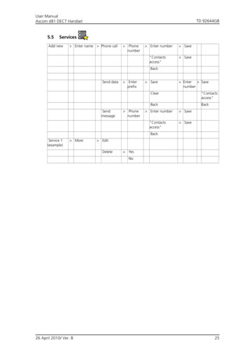
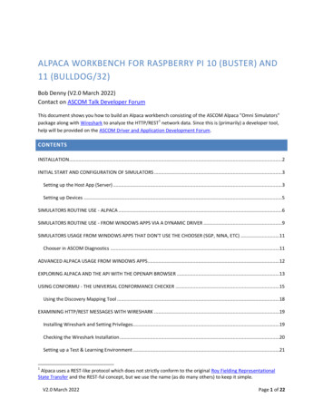
8. ASCOM i62 VoWiFi HANDSET & CHARGERDurable, robust, and feature rich ascom i62 VoWiFi handsets are designed to enable healthcare personnelto be mobile while still within quick reach in critical situations. The i62 handset is protected againstsplashing water making it suitable for use in wet room environments.ascom i62Multifunction ButtonIncoming Call LEDLoudspeakerHeadset ConnectorVolume ButtonsRear Belt ClipMute ButtonBacklit 1.8” TFT 65k ColourDisplay (176 x 220 pixels)Soft KeysCall KeyEnd Call Key (and on/off)Alpha-numeric Keys5 Way Navigation KeyShift/Key LockMicrophoneSound Off KeyEach ascom i62 handset is supplied with a desktop charger and a plug-top mains adapter.Select the UK AC plug from the changeable plugs provided and simply clip into place on the adapter.DesktopChargerMains Adapter andChangeable PlugsPRECONFIGURED HANDSETSThe 2 ascom i62 VoWiFi handsets supplied with ZXT964 Matrix IP-PBX bundle have been preconfigured asSIP extensions 151 and 152;i62 Wi-Fi settingsWi-Fi SSID: ADVENTWPA2 Password: LEGRAND1i62 Handset 1 SIP CredentialsDisplay Name: 151SIP User: 151SIP Password: Pass151!i62 Handset 2 SIP CredentialsDisplay Name: 152SIP User: 152SIP Password: Pass152!Doc No. FM0855 issue 2 Page 9
8. ASCOM i62 VoWiFi HANDSET & CHARGERAdditional ascom i62 VoWiFi handsets & chargers are available separately – Tynetec Part No. ZXT573.Note: a maximum of 5 x i62 handsets can be used per site.Additional i62 handsets must be configured as SIP extensions 153, 154 and 155 – see instructions below;CHANGING THE SIP SETTINGS ON AN i62 HANDSETSelect Menu soft keyNavigate to Settings and press Select soft keyScroll to Owner ID and press Select soft keySelect and edit the number as required (e.g. 153) and press Save soft keyNow Dial 40022 to display the hidden Admin menu.Scroll to VoIP and press Select soft keySelect Endpoint Number – press Edit soft key and then edit this field which is the desired extension numberon the Matrix IP-PBX (e.g. 153) and press the OK soft key when done.Select Endpoint ID and edit to match the Endpoint Number above (e.g. 153). Note to select numbers do along key press on the desired digit.Select Protocol, scroll down to SIP and press Edit soft key.Scroll down and select SIP Proxy Password press Edit soft key and change Password to desired setting (e.g.Pass153!) and press the OK soft key when done.Note to get the ! symbol, long key press on # key to display list of symbols.Press the Back soft key 6 times to return to the home screen.For more information refer to the ascom i62 user manuals (see section 6).Doc No. FM0855 issue 2 Page 10
9. MATRIX NENX IP-PBXThe Matrix NENX IP-PBX provides 2 CO (TWT) analogue trunks for connection to the XT2 system and theoutside world, an Ethernet port for up to 5 IP exten ce the programming is complete.Doc No. FM0855 issue 2 Page 16
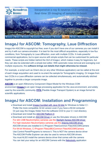
14. CHECK & UPGRADE DRAYTEK FIRMWAREConnect the power to the Access Point and switch on, wait for the 5G & 2.4G LED’s to illuminate.Connect LAN A1 to your Laptop Ethernet port using the UTP Patch lead supplied.Open a web browser and type: http://192.168.1.2 for a new or factory defaulted Access Point.Enter the default User Name of “admin” and the default Password of “admin” and click Login.Go to System Maintenance menu then select Firmware Upgrade as shown below;The Current Firmware Version should be 1.3.3 or higher.If an upgrade is required go to https://www.draytek.co.uk/support/downloads and select VigorAP 903.Download the latest version of the .all file and then Upload and Upgrade via the web page shown above.IMPORTANT: you must FACTORY RESET the Access Point after a firmware upgrade. To do this; make surethe device is powered-up with the ACT LED blinking and the 5G & 2.4G LED’s illuminated, hold down theFactory Reset button for about 10 secs until the 5G & 2.4G LED’s go out, then wait for about 60 seconds forthe device to re-initialise.Doc No. FM0855 issue 2 Page 17
15. MESH ROOT SETUPThe Mesh Root is the Access Point connected via LAN A1 to the Matrix IP-PBX via an Ethernet cable.Only one Mesh Root is required per site.Go to the Quick Start Wizard as shown below; Operation Mode: select “Mesh Root” from the Operation Mode list box then press Next Step I WiFi Setup: change the WiFi Name: to “ADVENT” and the Password: to “LEGRAND1”De-select the Enable 2nd WiFi checkbox and press Next Step I Admin Password: change the Admin Password or leave as default then press Next Step I Finish: a summary of the settings configuration will be shown, press FinishIDoc No. FM0855 issue 2 Page 18
15. MESH ROOT SETUPGo to the IP address of the new device (this should still be default at 192.168.1.2)Login with the usual passwords (if not already Logged-in previously)Go to the LAN menu and select General Setup as shown below;In the “LAN IP Network Configuration” de-select the Enable DHCP Client checkboxEnter the IP address: 192.168.0.50 (Mesh Root IP address)Enter the Subnet Mask: 255.255.255.0Enter the Default Gateway: 192.168.0.1 then press OK IGo to the Wireless LAN 2.4GHz menu and select General Setup as shown below;Ensure the Enable wireless LAN checkbox is selectedEnsure the Enable 2 Subnet (Simulate 2 APs) checkbox is de-selected then press OK IDoc No. FM0855 issue 2 Page 19
15. MESH ROOT SETUPStill in the Wireless LAN (2.4GHz) menu select Roaming as shown below;Repeat the same as above but for the Wireless LAN (5GHZ) optionSelect Strictly Minimum RSSI (-73dBm / 42%) then press OK IGo to the Wireless LAN (5GHz) menu and repeat the same settings as the Wireless LAN 2.4GHz i.e.Select General SetupEnsure the Enable wireless LAN checkbox is selectedEnsure the Enable 2 Subnet (Simulate 2 APs) checkbox is de-selected then press OK ISelect RoamingSelect Strictly Minimum RSSI (-73dBm / 42%) then press OK IDoc No. FM0855 issue 2 Page 20
16. MESH NODE SETUPThe Mesh Nodes are the Access Points connected wirelessly to the Mesh Root.Up to 7 Mesh Nodes can be added per site to increase the VoWiFi coverage.Power-up the Access Point to be setup as a Mesh Node and wait for the 2.4G and 5G LED’s to illuminate.Connect LAN A1 to your Laptop Ethernet port using the UTP Patch lead supplied.Open a web browser and type: http://192.168.1.2 for a new or factory defaulted Access Point.Enter the default User Name of “admin” and the default Password of “admin” and click Login.Go to the LAN menu and select General SetupIn the “LAN IP Network Configuration Setup” de-select the Enable DHCP Client checkboxEnter the IP address: 192.168.0.51 for Mesh Node 1For Mesh Node 2 enter: 192.168.0.52 through to Mesh Node 7 enter: 192.168.0.57Enter the same Subnet Mask: 255.255.255.0 for all Mesh Nodes 1-7Enter the same Default Gateway: 192.168.0.1 for all Mesh Nodes 1-7, then press OK IGo to the Wireless LAN (2.4GHz) menuSelect General SetupEnsure the Enable wireless LAN checkbox is selectedEnsure the Enable 2 Subnet (Simulate 2 APs) checkbox is de-selected then press OK ISelect RoamingSelect Strictly Minimum RSSI (-73dBm / 42%) then press OK IGo to the Wireless LAN (5GHz) menuSelect General SetupEnsure the Enable wireless LAN checkbox is selectedEnsure the Enable 2 Subnet (Simulate 2 APs) checkbox is de-selected then press OK ISelect RoamingSelect Strictly Minimum RSSI (-73dBm / 42%) then press OK IDisconnect the Mesh Node from your Laptop.Repeat the same process for all other Mesh Nodes being deployed on the site.Doc No. FM0855 issue 2 Page 21
17. MESH NODE DISCOVERYPower-up all Mesh RootsRe-connect your Laptop to LAN A1 on the Mesh Root Access PointOpen a web browser and type: http://192.168.0.50 and LoginGo to the MESH menu and select Mesh Setup as shown below;Scroll down to the Add Mesh Node section and press the Search buttonWait for the devices to appear in the Search List then select the check box next to each deviceEnter a Device Name for each device e.g. Node 1, Node 2, Node 3, etc. then press the Apply buttonGo to the Dashboard menu and verify all the new devices can be seen.Note: the refresh on this screen is about 60 seconds.Doc No. FM0855 issue 2 Page 22
18. MESH NODE DEPLOYMENTThe Draytek mesh solution supports a maximum of 8 Vigor AP 903’s in a mesh group, a mesh groupincludes 1 Mesh Root and up to 7 Mesh Nodes.IMPORTANT: Mesh Nodes can be a maximum of 3 hops away from the Mesh Root.A free Draytek Wireless App is available to simplify the setup of the mesh base/5683DEPLOYING MESH NODES1. With your Laptop connected to the Mesh Root in Dashboard view, or your mobile device runningthe Draytek Wireless App in Dashboard view, power-up the first Mesh Node in the desired location.2. Check the dB level (signal strength) displayed for the newly deployed Mesh Node, it must be no lessthan -73dB. For example -74dB or greater will be out of range and you need to move the MeshNode closer to the Mesh Root. If the dB l
This manual provides general information regarding the installation of Ascom VoWiFi handsets with the Matrix IP-PBX and Draytek Mesh Access Points. For more detailed information refer to the Ascom and Draytek installation and user guides. ASCOM DOCUMENTS You can request copies of the documents listed below from Tynetec's customer support.