Transcription
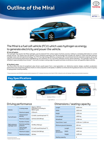
Outline of the MiraiThe Mirai is a fuel cell vehicle (FCV) which uses hydrogen as energyto generate electricity and power the vehicle. Fuel cell systemThe hydrogen that powers the Mirai, hydrogen, can be produced from various types of primary sources, making it a promising alternative to currentenergy sources. The Toyota Fuel Cell System (TFCS) combines proprietary fuel cell technology that includes the Toyota FC Stack and high-pressurehydrogen tanks with the hybrid technology. The TFCS has high energy efficiency compared with conventional internal combustion engines, along withsuperior environmental performance highlighted by zero emissions of CO2 and other pollutants during vehicle operation. The hydrogen tanks can berefuelled in approximately three minutes *1, and with an ample cruising range, the system promises convenience on par with gasoline engine vehicles. The Mirai’s valueThe Mirai offers the kind of exceptional value drivers would expect from a next-generation car: distinctive exterior design, excellent accelerationperformance and unmatched quietness thanks to motor propulsion at all speeds, in addition to enhanced driving pleasure due to a low center of gravitybringing greater handling stability.*1 Toyota measurement under SAEJ2601 standards (ambient temperature: 20 C; hydrogen tank pressure when fueled: 10 MPa). Fueling time varies with hydrogen fueling pressure and ambient temperature.Key SpecificationsHeight1,535 mmWheelbase 2,780 mmWidth 1,815 mmLength 4,890 mmDriving performanceVehicleFuel cell stackHigh-pressurehydrogen tankMotorCruising rangeApprox. 550 kmEstimated, according toNEDC CycleMaximum speed178 km/hVolume powerdensity3.1 kW/L (world top level *2)Maximum output114 kW (155 DIN hp)Number of tanks2Nominal workingpressure70 MPa (700 bar)Tank storagedensity *35.7 wt% (world top level *2)Maximum output113 kW (154 DIN hp)Maximum torque335 Nm*2 November 2014, Toyota data*3 Hydrogen storage mass per tank weightDimensions / seating capacityLength4,890 mmWidth1,815 mmHeight1,535 mmCurb weight1,850 kgWheelbase2,780 mmTrack (front / rear)1,535 mm / 1,545 mmMinimum ground clearance130 mmInteriordimensionsLength2,040 mmWidth1,465 mmHeight1,185 mmSeating capacity4
Main components of the MiraiMain ComponentsFuel cell boost converterFuel cell stackA compact, high-efficiency, high-capacityconverter newly developedto boost fuel cell stack voltage to 650 V.A boost converter is used to obtain anoutput with a higher voltagethan the input.Toyota’s first mass-productionfuel cell, featuring a compact sizeand world top level output density.Volume power density: 3.1 kW/LMaximum output: 114 kW(155 DIN hp)BatteryA nickel-metal hydridebattery which stores energyrecovered from decelerationand assists fuel cell stackoutput during acceleration.Power control unitMotorA mechanism to optimally control bothfuel cell stack output under variousoperational conditions and drivebattery charging and discharging.High-pressure hydrogen tankMotor driven by electricity generated by fuelcell stack and supplied by battery.Maximum output: 113 kW (154 DIN hp)Maximum torque: 335 N·mTank storing hydrogen as fuel. The nominalworking pressure is a high pressure level of70 MPa (700 bar). The compact, lightweighttanks feature world’s top level tank storagedensity.Tank storage density: 5.7 wt%Operating principalsSTEPSTEP5Motor is activatedand vehicle moves4Electricity suppliedto motorHydrogen refuelingElectricityFuel cell stackMotorElectricityAir (Oxygen)STEP1Air (oxygen) taken inPowergenerationOxygenSTEP2Oxygen and hydrogensupplied to fuel cell stackBatteryHigh-pressurehydrogen tankHydrogenSTEP3Electricity and watergenerated through chemicalreactionSTEP6Water emittedoutside vehicle
Driving performance of the MiraiThe Mirai offers far more than superior environmental performance. From the start of driving, the Mirai featuresa smooth and gliding feel, which promises exceptional driving pleasure, combining a high level of corneringperformance through winding roads with superior acceleration and quiet operation.An unprecedented drive feel born from motor-based drivingSuperior drive-startacceleration performanceSuperior acceleration offers drive-start acceleration (from 0 to 100km/h) of 9.6 seconds and passing acceleration of 3.0 seconds (from 40to 70 km/h)Outstanding quiet driveThe highly sound-insulating body and motor propulsion at all speedsdeliver outstanding quietnessConversation articulation comparison (Toyota measurements)5Good 80n FCV4(Toyota FCHV-adv)n HV1n HV23 n EV120 km/h AI (%)Passing acceleration 40–70 km/h (seconds)Acceleration performance comparison (Toyota measurements)GoodMIRAI10MIRAIn HV170n EVn FCV(Toyota FCHV-adv)n HV2121420062008201020122014Drive-start acceleration 0–100 km/h (seconds)Toyota Fuel Cell System (TFCS) achieves driving pleasureContributes to superior handling stabilityand quietnessHigh-level cornering performanceLow center of gravityAerodynamics Fuel cell stack, high-pressure hydrogen tanks and other power unitcomponents are placed under vehicle floor. The lower center of gravity raises handling stability and producesa comfortable driving experience by reducing changes in vehicleposition. The front-rear weight balance is adjusted to produce a midship feeldespite the front wheel drive design. Since the vehicle does not emit heated gases, the floor can be fullycovered. Air resistance is reduced to boost fuel efficiency. The design of the clearance lamps contributes to the aerodynamics. Aero-stabilizing fins are positioned next to the rear combinationlamps. This improves straight-driving stability.BatteryFuel cell stackHigh-pressure hydrogen tankFull underbody coveringClearance lampsAero-stabilizingdesigned to streamline finsairflow
Power performance of cold startcapabilityIssues concerning FCVs cold start capabilityMaintaining good power generation from a fuel cell requires water. In environments below the freezing point,however, excess water freezes, impeding the supply of air (oxygen) and hydrogen and causing a decrease inpower generation performance.Improving cold start capabilityWe made it possible to start the vehicle at –30 C and to achieve output at levels satisfactory for practical useimmediately after starting. Improved power generating performance immediately after starting below the freezing point Higher cell flow channel and electrode performance (exclusion of generated water and air (oxygen) diffusionwere improved to achieve excellent power generating performance even below the freezing point) Establishment of intra-cell water volume control technology (the volume of water is measured and controlledat a volume suitable for power generating performance below the freezing point) Improved warming-up performance Lower thermal capacity as a result of higher fuel cell stack output density Establishment of fuel cell rapid warm-up control technology (heat generated by the fuel cell is controlled todrastically reduce warm-up time)Example of evaluation in an extremely cold regionYellowknife, Canada evaluation (2014)Evaluation of fuel cell stack output performance immediately after starting after parking the vehicle outdoors overnight (17 hours)0Vehicle parking conditionsStart60% output 35 seconds after startingFuel cell stackoutput (%)100%100Ambient temperature ( C)–1080Vehicle stopped–20Start6060%40–20 C200–30 C–30Parked for 17 hours–400:00100% output 70 seconds after starting02040608010080100Elapsed time after starting (seconds)Accelerator position(% open)100%1008012:000:0012:0060402000204060Elapsed time after starting (seconds)Evaluations were performed in extremely cold regions including Yellowknife, Canada; Rovaniemi, Finland; and Shibetsu, Japan, confirming suitability forthese environments.
Fuel cell stack assemblyThe fuel cell stack assembly comprises the fuel cell stack, auxiliary components (hydrogen circulating pump, etc.)and fuel cell boost converter. Integrating these components achieves a smaller, lighter, and less expensive fuel cellstack assembly.Fuel cell stack assembly structure and main specificationsToyota FC stackType: Polymer electrolyte fuel cellMaximum output: 114 kW (155 DIN hp)Volume power density: 3.1 kW/L(world top level *1)Humidification system: Internalcirculation system(humidifier-less;world-first *1)Fuel cell boostconverterMaximum outputvoltage: 650 VNumber of phases:4 phasesAuxiliarycomponentsHydrogen circulating pump, etc.*1 November 2014; Toyota data
Toyota FC StackBreakthroughs in fuel cell technology have led to the creation of a smaller, lighter new fuel cell stack withenhanced performance.The new stack has a volume power density of 3.1 kW/L – among the world top level *3 –, and can now be mountedunderneath the floor of a sedan.Volume power density (kW/L)New fuel cell stack with increased output density(enhanced performance, more compact sized)World top level *33.5Volume power density3.1 kW/L3.0New fuel cell stack (Mirai)Titanium3D fine-mesh flow field(cathode, world-first*3)2.52.01.52008 model *1Stainless steel, straight channel1.02002 model *2Molded carbon, straight channel0.5Mass power density (kW/kg)00.51.01.52.02008 model *1 fuel cell stack2.5New fuel cell stack (Mirai)1.4 kW/L(Maximum output: 90 kW / volume: 64 L; weight: 108 kg)200 cells dual-line stacking 400 cells3.1 kW/L(Maximum output: 114 kW / volume: 37 L; weight: 56 kg)2.2 times bettervolume power density370 cellsSingle-linestackingConstant dimensionfasteningConstant pressure fasteningSpring2008 model *1 fuel cell stackNew fuel cell stack (Mirai)Maximum output90 kW114 kW (155 DIN hp)Volume power density / Mass power density1.4 kW/L / 0.83 kW/kg3.1 kW/L (World top level *3) / 2.0 kW/kgVolume / Weight64 L / 108 kg37 L / 56 kg (Cell fastener)Number of cells in one stack400 cells (dual-line stacking)370 cells (single-line stacking)Thickness1.68 mm1.34 mmWeight166 g102 gFlow channelStraight channel3D fine-mesh flow field (cathode, world-first *3)Motor room (SUV)Under floor (Sedan)CellMounting position*1 2008 model: Toyota FCHV-adv*2 2002 model: Toyota FCHV *3 November 2014, Toyota data
CellTo increase the power generating performance of the cells, it is important to enhance the water exclusion of produced water and promote the diffusionof air (oxygen).The new cells achieve a high current density by enhancing both the uniformity of generation in cell surfaces and electrode responsiveness withinnovative flow channel structures and electrodes.Higher performance of new cellsInnovations to cell flow channels (Cathode) Flowchannels: Using 3D fine-mesh flow field (world-first * ) simultaneously improves water exclusion and2air (oxygen) diffusion, achieving uniform generation in cell surfaces.3D fine-mesh flow field: A flow channel with a three-dimensional fine mesh structureNew cell (Mirai)2008 model cell *1Water produced from electric powergeneration tended to block the flowchannels, impeding the flow of air (oxygen)Generated water is quickly drawn out through hydrophilic 3DWaterfine-mesh flow field (world-first*2), preventing obstructionexclusion of the flow of air (oxygen) by accumulated water.Air (Oxygen)World-first *2HydrogenWide flow channel rib widthHydrogenwidthibrlennahcNarrow flowAir (Oxygen)DiffusibilityFlow channel rib width is large meaning the generatedwater tends to be retained, impeding the diffusion ofair (oxygen) to the catalyst layer and reducing powergeneration performance.Turbulent flows, resulting from the narrowness ofthe flow channel rib width, promote the diffusion ofoxygen to the catalyst layer.Electrode innovations Theelectrolyte membrane was made thinner, the diffusion performance of the gas diffusion layer wasincreased, and the catalyst was hyper-activated to greatly enhance electrode responsiveness.Gas diffusion layer: Lower density andthinner base materialGas diffusion performancemore than doubledCell voltage (V)World top level*22008 model cell *1 Current density New cell2.4 times higherElectrolyte membrane:Thinner by one-thirdProton conductivity increasedby 3 timesCatalyst layer:Highly reactive Pt/Co alloy catalystActivity increased by 1.8 timesCurrent density (A/cm2)*1 2008 model: Toyota FCHV-adv *2 November 2014, Toyota data
Internal circulation system –Humidifier-lessThe new fuel cell stack performs self-humidification by circulating water produced from power generation withinthe cells, eliminating the need for external humidification. This makes it possible to eliminate the humidifier(world-first *1), making the system smaller and lighter.Internal circulation system – Humidifier-lessThe system self-humidifies by circulating water (water vapor) produced from powergeneration within the cells in order to maintain the proton conductivity performanceof the electrolyte membrane.Thinner electrolytemembraneHigh-pressurehydrogen tankPressure controller1World-first *Promotes back-diffusionof generated waterHydrogeninletElectrolyte membraneAir outletIncreased hydrogencirculation volumeIncreased water vapor supplyfrom the anode upstream todownstreamInternalcirculationSystem simplified by eliminatinghumidifierHydrogencirculating pumpHydrogenoutlet–15 LWeight reduction: –13 kgSize reduction:ProtonHumidificationfrom anodeSuppression ofevapotranspirationAir and hydrogen flow in oppositedirections, humidifying upstreamair flow, which tends to dry outIncreases coolant water volumein upstream air and suppressestemperature increase and alsosuppresses evapotranspiration ofgenerated water.Air inlet (dry)Air compressorExternal circulating humidifier (previous system)The system humidifies the supplied air (oxygen) using a humidifier to maintain the proton conductivity of the electrolyte membrane.PressurecontrollerHydrogeninletEarlier systems useda humidifierExternal circulationHigh-pressurehydrogen tankLess back-diffusionof generated waterElectrolyteAirmembrane outletHydrogencirculating pumpHydrogenoutletLow volume of circulatedhydrogen, and low supplyvolume of water vapor fromthe anode upstream todownstreamProtonAir inlet(wet)HumidifierOnly water vapor is retrieved from theemitted air, and this is used to humidifythe supplied air.Air compressor*1 November 2014, Toyota data
Fuel cell boost converterBy developing a high-capacity fuel cell boost converter, it was possible to increase the voltage ofthe motor, reduce the number of fuel cell stack cells, and reduce the size and weight of the system.Also, innovations to the voltage-boost control and case structure provide exceptionally quietoperation.In addition, the new system can be used with existing hybrid units, enhancing reliability and greatlyreducing costs.Main specifications of fuel cell boost converterMaximum output voltage650 VVolume13 LNumber of phases4Cooling methodWater-cooledFuel cell boost converterSpecially developedfor the FCVMIRAI2008 model *1Fuel cellstackFuel cell stackNewlydevelopedFuel cellNewly developedFuel cellFuel cellboostconverterBatteryExisting unitsusedPower controlunitBatteryExisting units usedExisting unitsusedUse of existinghybrid unitsMotorExisting unitsusedPower control unitNewly developedMotorMotor650 V250 VMotorNewly developed*1 2008 model: Toyota FCHV-adv
High-pressure hydrogen tankIn-house development of high-pressure hydrogen tank since 20001Tank storage density **1 Hydrogen storage mass per tank weightLighter weight achieved through innovations of carbon fiber reinforcedplastic layer structureTank storage density of 5.7 wt% achieved, a world top level *2World top level *2Innovations to the plastic liner configuration and efficientlayering pattern resulted in a reduction of approximately40% in the amount of carbon fiber usedCylindrical sectionBoundarysectionBoundarysectionCylindrical sectionPlastic linerDomesectionDomesectionLow anglehelical windingPlastic liner (seals in hydrogen)BossHigh anglehelical windingCarbon fiber-reinforced plastic layer(ensures pressure resistance)Glass fiber-reinforced plastic layer(protects surface)HoopwindingHigh-pressure hydrogen tankNominal workingpressure70 MPa (700 bar)Tank storagedensity5.7 wt% (world top level *2)Tank internalvolume122.4 L (front tank: 60.0 L,rear tank: 62.4 L)Hydrogenstorage massApprox. 5.0 kgConventional technologyNew technology*2 November 2014, Toyota dataHydrogen refuelingIn response to new fueling standards *3 (the same in Japan, the US, and Europe),fueling time of approximately 3 minutes *4 has been achieved*3 (Refueling devices) ISO 17268: Gaseous Hydrogen Land Vehicle Refueling Connection Devices(Refueling methods) SAE J2601: Fueling Protocols for Light Duty Gaseous Hydrogen Surface Vehicles(Communications fueling) SAE J2799: 70 MPa Compressed Hydrogen Surface Vehicle Fueling Connection Device and Optional Vehicle to StationCommunications*4 Toyota measurement under SAEJ2601 standards (ambient temperature: 20 C; hydrogen tank pressure when fueled: 10 MPa).Fueling time varies with hydrogen fueling pressure and ambient sensorTankinformationInfrared raytransmitterHydrogenHigh-pressurehydrogen tankVehicleRefuelingtime ofapprox. 3minutes *4NozzleCommunicationsfunctions given tonozzle and fuel fillerHydrogen stationNew model2008 model(MIRAI)(Toyota FCHV-adv)
The new fuel cell stack performs self-humidification by circulating water produced from power generation within the cells, eliminating the need for external humidification. This makes it possible to eliminate the humidifier (world-first *1), making the system smaller and lighter. Internal circulation system - Humidifier-less