Transcription
WESTERN SPECIFIER GUIDEfor products manufactured in White City, OregonWSG 03/14/2013
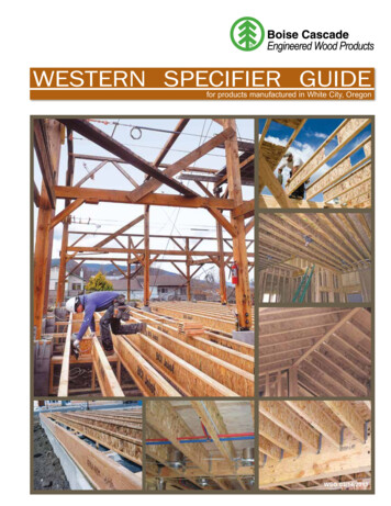
2The SIMPLE FRAMING SYSTEM Makes Designing Homes EasierArchitects, engineers, and designers trustBoise Cascade's engineered wood productsto provide a better system for framing floorsand roofs.It's the SIMPLE FRAMING SYSTEM ,featuring beams, joists and rim boardsthat work together as a system, so youspend less time cutting and fitting. Infact, the SIMPLE FRAMING SYSTEM uses fewer pieces and longer lengthsthan conventional framing, so you'llcomplete jobs in less time.You'll Build Better Homeswith theSIMPLE FRAMING SYSTEM Now it's easier than ever to designand build better floor systems. Whenyou specify the SIMPLE FRAMINGSYSTEM , your clients will have fewerproblems with squeaky floors andceiling gypsum board cracks. TheSIMPLE FRAMING SYSTEM alsomeans overall better floor and roofframing than dimension lumber allows.Better FramingDoesn't Have to Cost MoreTable of ContentsBoise Cascade Engineered WoodProducts' SIMPLE FRAMINGSYSTEM often costs less thanconventional framing methods whenthe resulting reduced labor andmaterials waste are con sidered.There's less sorting and cost associ ated with disposing of waste becauseyou order only what you need.Although our longer lengths help yourclients get the job done faster, theycost no more.Environmentally SoundAs an added bonus, floor and roofsystems built with BCI Joists requireabout half the number of trees asthose built with dimension lumber.This helps you design a home bothyou and future generations will beproud to own.What Makes the SIMPLEFRAMING SYSTEM So Simple? Floor and Roof Framing withBCI JoistsLight in weight, but heavy-duty,BCI Joists have a better strength /weight ratio than dimension lumber.Knockouts can be removed forProduct Profiles, BCI Specifications . . . . . . . . . . . . . . . . . . . . . . . . 3BCI Residential Floor Span Tables, About Floor Performance,One Hour Floor/Ceiling Assembly . . . . . . . . . . . . . . . . . . . . . . . . . . . . 4BCI Floor Framing Details . . . . . . . . . . . . . . . . . . . . . . . . . . . . . . 5 - 6BCI Joist Hole Location and Sizing . . . . . . . . . . . . . . . . . . . . . . . . . . 7BCI Cantilever Details, Web Stiffener Requirements . . . . . . . . . 8 - 9BCI Floor Load Tables. . . . . . . . . . . . . . . . . . . . . . . . . . . . . . . . 10 - 12BCI Roof Framing Details . . . . . . . . . . . . . . . . . . . . . . . . . . . . 13 - 14BCI Roof Span Tables . . . . . . . . . . . . . . . . . . . . . . . . . . . . . . . 15 - 18BCI Roof Load Tables . . . . . . . . . . . . . . . . . . . . . . . . . . . . . . . 19 - 23BCI Design Properties, BCI Allowable Nail Spacing. . . . . . . . . . . . 24Boise Cascade Rimboard Products . . . . . . . . . . . . . . . . . . . . . . . . . 25cross-ventila tion and wiring. Ceilings Framed with BCI JoistsThe consistent size of BCI Joistshelps keep gypsum board flat andfree of unsightly nail pops and uglyshadows, while keeping finish workto a minimum. VERSA-LAM Beams for Floorand Roof FramingThese highly-stable beams arefree of the large-scale defects thatplague dimension beams. Theresult is quieter, flatter floors (nocamber) and no shrinkage-relatedcall-backs. Boise Cascade RimboardBoise Cascade Engineered WoodProducts offer several engineeredrimboard products regionally,including BC RIM BOARD OSB,VERSA-RIM , VERSA-STRAND 0.8 and VERSA-LAM 1.4 1800(check supplier or Boise CascadeEWP rep for availability). These products work with BCI Joists toprovide a solid connection at thecritical floor/wall intersection.VERSA-LAM Products, Specifications, Allowable Holes. . . . . . . . . 26VERSA-LAM Details, Multiple Member Connectors . . . . . . . . . . . . 27VERSA-LAM Floor Load Tables (100% Load Duration). . . . . . . . . 28VERSA-LAM Snow Roof Load Tables (115% Load Duration) . . . . . . 29VERSA-LAM Non-Snow Roof Load Tables(125% Load Duration). . . . . . . . . . . . . . . . . . . . . . . . . . . . . . . . . . . . 30VERSA-LAM Closest Allowable Nail Spacing . . . . . . . . . . . . . . . . . 31VERSA-LAM Design Values. . . . . . . . . . . . . . . . . . . . . . . . . . . . . . . 31VERSA-LAM Columns, VERSA-STUD . . . . . . . . . . . . . . . . . . . . . 32Computer Software . . . . . . . . . . . . . . . . . . . . . . . . . . . . . . . . . . . . . . 33Framing Connectors . . . . . . . . . . . . . . . . . . . . . . . . . . . . . . . . . 34 - 35Lifetime Guarantee . . . . . . . . . . . . . . . . . . . . . . . . . . . . . . Back CoverOn the cover (main photo): Adroit Construction: Ashland, OR: Willow Winds RestorationBoise Cascade EWP Western Specifier Guide 03/14/2013
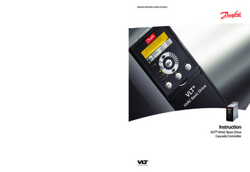
Western Product Profiles3 :HVWHUQ 3URGXFW 3URILOHV%&, -RLVWV%&, ȳ ȴ %&, ȴ ó ȶ %&, ó ȳ ȳ ó ȶ %&, ȴ ó ȶ %&, 9(56 / 0 9(56 / 0 9(56 / 0 9(56 / 0 ó ȴ ȶ ȴ ȶ ó WR ó WR ó WR ó WR ó õ ó ô ó õ ó ô ó 6RPH SURGXFWV PD\ QRW EH DYDLODEOH LQ DOO PDUNHWV &RQWDFW \RXU %RLVH &DVFDGH (:3 UHSUHVHQWDWLYH IRU DYDLODELOLW\ %&, DQG 9(56 / 0 SURGXFWV VKDOO EH LQVWDOOHG LQ GU\ XVH DSSOLFDWLRQV RQO\ SHU WKHLU UHVSHFWLYH ,&& (65 HYDOXDWLRQ UHSRUWV BCI Joist Architectural SpecificationsScope: This work includes the completefurnishing and installation of all BCI Joistsas shown on the drawings, herein specifiedand necessary to complete the work.Materials: BCI Joists shall be manu factured by Boise Cascade EngineeredWood Products with oriented strand boardwebs, VERSA-LAM laminated veneerlumber flanges and water proof, structuraladhesives.Joist webs shall be graded Structural IExposure 1 by an agency listed by a modelcode evaluation service. Strands on theface layers of the web panels shall beoriented vertically in the joist. The webpanels shall be glued together to form acontinuous web member. The web panelsshall be machined to fit into a groove inthe center of the wide face of the flangemembers so as to form a pressed glue jointat that junction.Boise Cascade EWP Western Specifier Guide 03/14/2013Design: The BCI Joists shall be sizedand detailed to fit the dimensions and loadsindicated on the plans. All designs shall bein accordance with allowable values andsection properties developed in accordancewith ASTM D5055 and listed in thegoverning code evaluation service's report.Drawing: Additional drawings showinglayout and detail necessary for determiningfit and placement in the building are (arenot) to be provided by the supplier.Fabrication: The BCI Joists and sectionproperties shall be manufactured in a plantevaluated for fabrication by the governingcode evaluation service and under thesupervision of a third-party inspectionagency listed by the correspondingevaluation service.Storage and Installation: The BCI Joists, if stored prior to erection, shall bestored in a vertical and level position andpro tected from the weather. They shallbe handled with care so they are notdamaged.The BCI Joists are to be installed inaccordance with the plans and the BoiseCascade Engineered Wood ProductsInstallation Guide. Temporary constructionloads which cause stresses beyond designlimits are not permitted. Erection bracingshall be provided to keep the BCI Joistsstraight and plumb as required and toassure adequate lateral support for theindividual BCI Joists and the entire systemuntil the sheathing material has beenapplied.Codes: The BCI Joists shall be evaluatedby a model code evaluation service.
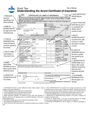
Residential Floor Span Tables4About Floor Performanceincrease the joist depth, limit joist deflections, glue and screw athicker, tongue-and-groove subfloor, install the joists verticallyplumb with level-bearing supports, and install a direct-attachedceiling to the bottom flanges of the joists.Homeowner’s expectations and opinions vary greatly due to thesubjective nature of rating a new floor. Communication with theultimate end user to determine their expectation is critical. Vibrationis usually the cause of most complaints. Installing lateral bridging mayhelp; however, squeaks may occur if not installed properly. Spacingthe joists closer together does little to affect the perception of thefloor's performance. The most common methods used to increasethe performance and reduce vibration of wood floor systems is toJoistDepth9½"11⅞"14"16"BCI JoistSeriesThe floor span tables listed below offer three very differentperformance options, based on performance requirements of thehomeowner.CAUTION THREE STAR FOUR STAR Live Load deflection limited to L/480: Thecommon industry and design communitystandard for residential floor joists, 33% stifferthan L/360 code minimum. However, floorperformance may still be an issue in certainapplications, especially with 91/2" and 117/8"deep joists without a direct-attached ceiling.Live Load deflection limited to L/960 :In addition to providing a floor that is 100%stiffer than the three star floor, fieldexperience has been incorporated into thevalues to provide a floor with a premiumperformance level for the more discriminatinghomeowner. MINIMUM STIFFNESSALLOWED BY CODE CAUTIONLive Load deflection limited to L/360:Floors that meet the minimum buildingcode L/360 criteria are structurally sound tocarry the specified loads; however, there is amuch higher risk of floor performance issues.This table should only be used for applicationswhere floor performance is not a "o.c.24"o.c.32"o.c.5000 ''17'–0''15'–6''13'–11''12'–0''6000 1'–6''11'–6''10'–0''10'–0''9'–10''6500 '18'–8''17'–8''16'–5''14'–3''5000 ''19'–4''17'–7''15'–9''13'–4''6000 6''21'–6''20'–0''17'–11''14'–10''6500 ��3''22'–2''20'–11''18'–10''14'–10''60 ''23'–6''22'–3''20'–9''16'–4''90 �0''26'–6''25'–0''23'–3''19'–4''5000 �4''21'–0''19'–2''17'–2''13'–11''6000 �9''23'–11''21'–10''19'–6''15'–5''6500 6''25'–1''22'–11''20'–6''15'–5''60 �3''26'–8''25'–3''21'–10''16'–4''90 0''30'–0''28'–3''26'–0''19'–6''6000 �6''25'–6''23'–4''20'–10''15'–9''6500 ''26'–11''24'–6''21'–1''15'–9''60 ��4''29'–6''27'–4''21'–10''16'–4''90 ��4''33'–2''31'–3''26'–2''19'–7''18"90 ��8''36'–2''34'–1''31'–9''23'–10''20"90 ��11''39'–1''36'–10''32'–11''24'–8'' Table values based on residential floor loads of 40 psf live load and 10 psf deadload (12 psf dead load for BCI 90 2.0 joists). Span values assume 23/32" min plywood/OSB rated sheathing is glued and nailed tojoists for composite action (joists spaced at 32" o.c. require sheathing rated for suchspacing - ⅞" plywood/OSB). Table values represent the most restrictive of simple or multiple span applications. Table values are the maximum allowable clear distance between supports. Table values assume minimum bearing lengths without web stiffeners for joistdepths of 16" inches and less (18" & 20" joists require web stiffeners at all bearinglocations). Floor tile will increase dead load and may require specific deflection limits, contactBoise Cascade EWP Engineering for further information. This table was designed to apply to a broad range of applications. It may bepossible to exceed the limitations of this table by analyzing a specific applicationwith the BC CALC sizing software.One-Hour Fire Resistive AssemblyICC ESR 1336123See Boise Cascade Fire Design & Installation Guide US version for specific specific assembly informationand other fire resistive options or contact your localBoise Cascade representative.FIRE ASSEMBLY COMPONENTS1. Min. 23/32" thick tongue and groove sheathing (exterior glue), installed with longedge perpendicular to joist length, staggered one joist spacing with adjacentsheets, and glued to joists with construction adhesive.2. BCI Joists at 24" o.c. or less.3. Two layers ⅝" Type X or two layers ½" Type C gypsum board, installed perFigures 2 or 3 of ICC ESR 1336.SOUND ASSEMBLY COMPONENTSWhen constructed with resilient channels Add carpet & pad to fire assembly: Add 3½" glass fiber insulation to fire assembly: Add an additional layer of minimum ⅝" sheathingand 9½" glass fiber insulation to fire assembly:STC 54STC 55IIC 68IIC 46STC 61IIC 50ororBoise Cascade EWP Western Specifier Guide 03/14/2013
Floor Framing5127(7KH LOOXVWUDWLRQ EHORZ LV VKRZLQJ VHYHUDO VXJJHVWHG DSSOLFDWLRQV IRU WKH %RLVH &DVFDGH %&, -RLVW EORFN RU [ VTXDVKµ EORFN RQ HDFK VLGH (:3 SURGXFWV ,W LV QRW LQWHQGHG WR VKRZ DQ UHTXLUHG ZKHQ VXSSRUWLQJ D ORDG EHDULQJ ZDOO DERYH DFWXDO KRXVH XQGHU FRQVWUXFWLRQ 12 0,'63 1 %5,'*,1* ,6 5(48,5(' )25 %&, -2,676)25 ,167 // 7,21 67 %,/,7 7HPSRUDU\ VWUXW OLQHV [ PLQ RQ FHQWHU PD[ )DVWHQ DW HDFK MRLVW ZLWK G QDLOV PLQLPXP :KHQ LQVWDOOLQJ %RLVH &DVFDGH (:3 SURGXFWV ZLWK WUHDWHG ZRRG XVH RQO\ FRQQHFWRUV IDVWHQHUV WKDW DUH DSSURYHG IRU XVH ZLWK WKH FRUUHVSRQGLQJ ZRRG WUHDWPHQW 9(56 / 0 KHDGHURU D %&, -RLVW KHDGHU ó NQRFNRXW KROHV DW DSSUR[LPDWHO\ R F DUH SUH SXQFKHG 'LPHQVLRQ OXPEHU LV QRW VXLWDEOH IRU XVH DV D ULP ERDUG LQ %&, IORRU V\VWHPV %&, ULP MRLVW 6HH SDJH 6HH SDJH IRU DOORZDEOH KROH VL]HV DQG ORFDWLRQ %RLVH &DVFDGH 5LPERDUG 6HH SDJHV DQG )RU ORDG EHDULQJ FDQWLOHYHU GHWDLOV VHH SDJH For load bearing cantilever details, see page 9.BCI Joists, VERSA-LAM and ALLJOIST must be stored, installed and used in accordancewith the Boise Cascade EWP Installation Guide, building codes, and to the extent notinconsistent with the Boise Cascade EWP Installation Guide, usual and customary buildingpractices and standards. VERSA-LAM , ALLJOIST , and BCI Joists must be wrapped,covered, and stored off of the ground on stickers at all times prior to installation. VERSA-SAFETY WARNINGDO NOT ALLOW WORKERS ON BCI JOISTS UNTIL ALLHANGERS, BCI RIM JOISTS, RIM BOARDS, BCI BLOCKINGPANELS, X-BRACING AND TEMPORARY 1x4 STRUT LINES AREINSTALLED AS SPECIFIED BELOW. SERIOUS ACCIDENTSCAN RESULT FROM INSUFFICIENT ATTENTION TO PROPERBRACING DURING CONSTRUCTION. ACCIDENTS CAN BEAVOIDED UNDER NORMAL CONDITIONS BY FOLLOWINGTHESE GUIDELINES: Build a braced end wall at the end of the bay, or permanentlyinstall the first eight feet of BCI Joists and the first course ofsheathing. As an alternate, temporary sheathing may be nailed tothe first four feet of BCI Joists at the end of the bay. All hangers, BCI rim joists, rim boards, BCI blocking panels, andx-bracing must be completely installed and properly nailed as eachBCI Joist is set. Install temporary 1x4 strut lines at no more than eight feet oncenter as additional BCI Joists are set. Nail the strut lines to thesheathed area, or braced end wall, and to each BCI Joist with two8d nails. The ends of cantilevers must be temporarily secured by strut lineson both the top and bottom flanges. Straighten the BCI Joists to within 1/2 inch of true alignmentbefore attaching strut lines and sheathing. Remove the temporary strut lines only as required to install thepermanent sheathing. Failure to install temporary bracing may result in sideways bucklingor roll-over under light construction loads. Do not stack construction materials (sheathing, drywall, etc)in the middle of BCI Joist spans, contact Boise Cascade EWPEngineering for proper storage and shoring information.Boise Cascade EWP Western Specifier Guide 03/14/20139(56 / 0 /9/ EHDP (QGZDOO EORFNLQJ DV UHTXLUHG SHU JRYHUQLQJ EXLOGLQJ FRGH %&, -RLVW %ORFNLQJ LV UHTXLUHG ZKHQ %&, -RLVWV DUH FDQWLOHYHUHG LAM , ALLJOIST and BCI Joists are intended only for applications that assure noexposure to weather or the elements and an environment that is free from moisture fromany source, or any pest, organism or substance which degrades or damages wood or gluebonds. Failure to correctly store, use or install VERSA-LAM , ALLJOIST , and BCI Joist inaccordance with the Boise Cascade EWP Installation Guide will void the limited warranty.
Floor Framing Details6Additional floor framing details available with BC FRAMER software (see page 33)END BEARING DETAILSF07F07AF02F01%&, -RLVW EORFNLQJ %&, ULP MRLVW 1DLO %RLVH &DVFDGH 5LPERDUG WR %&, -RLVWV ZLWK G QDLO LQWR HDFK IODQJH 'LPHQVLRQ OXPEHU LV QRW VXLWDEOH IRU XVH DV ULP ERDUG ZLWK %&, -RLVWV 'LPHQVLRQ OXPEHU LV QRW VXLWDEOH IRU XVH DV ULP ERDUG ZLWK %&, -RLVWV F27AF522QH G QDLO HDFK VLGH DW EHDULQJ7RS )ODQJH RU )DFH 0RXQW -RLVW DQJHU ó PLQLPXP EHDULQJ OHQJWK7R OLPLW VSOLWWLQJ IODQJH VWDUW QDLOV DW OHDVW ó IURP HQG 1DLOV PD\ QHHG WR EH GULYHQ DW DQ DQJOH WR OLPLW VSOLWWLQJ RI EHDULQJ SODWH 9(56 / 0 F08F036ROLG EORFN DOO SRVWV IURP DERYH WR EHDULQJ EHORZ 1RWH %&, IORRU MRLVW PXVW EH GHVLJQHGWR FDUU\ ZDOO DERYH ZKHQ QRW VWDFNHGRYHU ZDOO EHORZ INTERMEDIATE BEARING DETAILSF06)RU ORDG EHDULQJ ZDOO DERYH VWDFNHG RYHU ZDOO EHORZ %ORFNLQJ PD\ EH UHTXLUHG DW LQWHUPHGLDWH EHDULQJV IRU IORRU GLDSKUDJP SHU ,5& LQ KLJK VHLVPLF DUHDV FRQVXOW ORFDO EXLOGLQJ RIILFLDO F09/RDG EHDULQJ ZDOO DERYH VWDFNHG RYHU ZDOO EHORZ %&, -RLVW EORFNLQJ F10-RLVW DQJHU%DFNHU EORFN PLQLPXP ZLGH 1DLO ZLWK G QDLOV )LOOHU EORFN 1DLO ZLWK G QDLOV %DFNHU EORFN UHTXLUHG ZKHUH WRS IODQJH MRLVW KDQJHU ORDG H[FHHGV OEV ,QVWDOO WLJKW WR WRS IODQJH F58'RXEOH %&, -RLVW &RQQHFWLRQ )LOOHU %ORFN VHH FKDUW EHORZ:HE )LOOHU 1DLOLQJ RQ FHQWHU&RQQHFWLRQ YDOLG IRU DOO DSSOLFDWLRQV &RQWDFW %RLVH &DVFDGH (:3 (QJLQHHULQJ IRU VSHFLILF FRQGLWLRQV LATERAL SUPPORT BCI Joists shall be laterally supported at the ends withhangers, rimboard, BCI rim joist or blocking panels. BCI blocking panels or rimboard are required at cantileversupports. Blocking may be required at intermediate bearings for floordiaphragm per IRC in high seismic areas, consult localbuilding official.MINIMUM BEARING LENGTH FOR BCI JOISTS Minimum Bearing Lengths: 1½" end bearing,3½" intermediate and adjacent cantilever bearing. Longer bearing lengths allow higher reaction values. Refer tothe building code evaluation report or the BC CALC software.NAILING REQUIREMENTS BCI rim joist, rim board or closure panel to BCI joist:– Rims or closure panel 1¾ inches thick and less:2-8d nails, one each in the top and bottom flange.– BCI 5000 rim joist: 2-10d box nails, one each in thetop and bottom flange.– BCI 6000, 60 rim joist: 2-16d box nails, one each inthe top and bottom flange.– BCI 6500, 90 rim joist: Toe-nail top flange to rim joistwith 2-10d box nails, one each side of flange. BCI rim joist, rim board or BCI blocking panel to support:– Min. 8d nails @ 6" o.c. per IRC.– Connection per design professional of record'sspecification for shear transfer.%&, -RLVW 6ORSH &XW 5HLQIRUFHPHQW)ORRU -RLVW %ORFNLQJ SHU ,5& 5HTXLUHG LQ VHLVPLFGHVLJQ FDWHJRULHV ' DQG KLJKHU IRU IORRU GLDSKUDJP UHTXLUHG IRU DOO MRLVW W\SHV F28%&, -RLVW RU %& 5LPERDUG %ORFNLQJ ,QWHUPHGLDWH %HDULQJ 1DLO SHU ORFDO FRGH SURYLVLRQV &URVV EUDFLQJ 2. DV EORFNLQJ RQO\ LI VXSSRUW EHORZ LV QRW D EUDFHG ZDOO SDQHO RU VKHDU ZDOO DQG QR ZDOO H[LVWV DERYH [ EORFN %&, ULP MRLVW F05'HWDLO EHORZ UHVWRUHV RULJLQDO DOORZDEOH VKHDU UHDFWLRQ YDOXH WR FXW HQG RI %&, MRLVW %&, -RLVW VKDOO QRW EH XVHG DV D FROODU RU UDIWHU WHQVLRQ WLH [ PLQ UDIWHU 5DIWHU VKDOO EH VXSSRUWHG E\ ULGJH EHDP RU RWKHU XSSHU EHDULQJ VXSSRUW F14 HHO'HSWKVHHWDEOHEHORZ PLQ PD[ %&, GHSWK [ EORFNLQJ UHTXLUHG DW EHDULQJ QRW VKRZQ IRU FODULW\ PLQ SO\ZRRG 26% UDWHG VKHDWKLQJ DV UHLQIRUFHPHQW ,QVWDOO UHLQIRUFHPHQW ZLWK IDFH JUDLQ KRUL]RQWDO ,QVWDOO RQ ERWK VLGHV RI WKH MRLVW WLJKW WR ERWWRP IODQJH /HDYH PLQLPXP ô JDS EHWZHHQ UHLQIRUFHPHQW DQG ERWWRP RI WRS IODQJH SSO\ FRQVWUXFWLRQ DGKHVLYH WR FRQWDFW VXUIDFHV DQG IDVWHQ ZLWK URZV RI PLQ G ER[ QDLOV DW R F OWHUQDWH QDLOLQJ IURP HDFK VLGH DQG FOLQFK 6KHDWKLQJ RUULPERDUG FORVXUH%&, -RLVW EORFNLQJ UHTXLUHG IRU FDQWLOHYHU )RU ORDG EHDULQJ FDQWLOHYHU VHH SDJHV DQG 8SOLIW RQ EDFNVSDQ VKDOO EH FRQVLGHUHG LQ DOO FDQWLOHYHU GHVLJQV Minimum Heel DepthEndRoof PitchWallBearing 6/12 7/12 8/12 9/122 x 4 43 8" 45 16 " 4¼" 4¼"2x610/12 12/124¼"4¼"33 8" 33 16 " 25 16 " 2¾" 29 16 " 2¼" BCI joist to support:BCI RIM JOISTS AND BCI BLOCKING– 2-8d nails, one on each side of the web, placed1½ inches minimum from the end of the BCI JoistVertical Load Capacityto limit splitting.NoDepthW.S.(2)W.S.(1) [in]Series Sheathing to BCI joist:9½" 5000 1.7, 6000 1.8, 6500 1.82300N/A– Prescriptive residential floor sheathing nailing requires 8d5000 1.7, 6000 1.8, 6500 1.82150N/Acommon nails @ 6" o.c. on edges and @ 12" o.c. in the field11⅞"602.0,902.02500N/A(IRC Table R602.3(1)).5000 1.7, 6000 1.8, 6500 1.82000N/A– See closest allowable nail spacing limits on page 24 for floor14"60 2.0, 90 2.02400N/Adiaphragm nailing specified at closer spacing than IRC.6000 1.8, 6500 1.81900250016"– Maximum nail spacing for minimum lateral stability: 18" for602.0,902.023002700BCI 5000, 24" for larger BCI joist series.18" 60 2.0, 90 2.0N/A2700– 14 gauge staples may be substituted for 8d nails if the staples20" 90 2.0N/A2700penetrate at least 1 inch into the joist.– Wood screws may be acceptable, contact local building (1) No web stiffeners requiredofficial and/or Boise Cascade EWP Engineering for(2) Web stiffeners required at each end of blocking, valuesfurther information.not applicable for rim joistsBACKER AND FILLER BLOCK DIMENSIONSN/A: Not applicableSeries5000 1.76000 1.86500 1.860 2.090 2.0Backer Block Thickness¾" or ⅞" wood panels1⅛" or two ½" wood panels1⅛" or two ⅝" wood panels1⅛" or two ½" wood panels2x lumberFiller Block ThicknessTwo ¾" wood panels or 2x2x 7 16" or ½" wood panel2x ⅝" or ¾" wood panel2x 7 16" or ½" wood panelDouble 2x lumber Cut backer and filler blocks to a maximum depth equal tothe web depth minus ¼" to avoid a forced fit.WEB STIFFENER REQUIREMENTS See Web Stiffener Requirements on page 9.PROTECT BCI JOISTS FROM THE WEATHER BCI Joists are intended only for applicationsthat provide permanent protection from theweather. Bundles of BCI Joists should becovered and stored off of the ground on stickers.Boise Cascade EWP Western Specifier Guide 03/14/2013
BCI Joist Hole Location & Sizing7BCI Joists are manufactured with 11/2" round perforated knockouts in the web at approximately 12" on centerMinimum spacing 2x greatest dimensionof largest hole (knockouts exempt)DDDO NOTcut or notchflange(see table below)(see table below)6"6"6"A 11/2" round hole may becut anywhere in the web.Provide at least 3" ofclearance from other holes.No holes (except knockouts)allowed in bearing zones6"6"Do not cut holeslarger than 11/2"round in cantilevers.DOcut in web areaas specifiedMinimum distance from support, listed in table below, is required for all holes greater than 1½"MINIMUM DISTANCE (D) FROM ANY SUPPORT TO THE CENTERLINE OF THE HOLERound Hole Diameter [in]Rectangular Hole Side 5'-11''7'-2''234567Rectangular Hole Side [in]Span[ft]38Round Hole Diameter '5'-0''6'-2''7'-4''8'-6''9'-7''23567887/8Round Hole Diameter ''5'-10''7'-1''8'-3''9'-9''11'-0''Round Hole Diameter [in]234567887/8101112131415Rectangular Hole Side 7''4'-9''5'-10''7'-2''8'-4''9'-6''10'-9''Round Hole Diameter [in]234567887/8101112131415Rectangular Hole Side 5''4'-6''5'-7''6'-6''7'-9''8'-9''9'-10'' 10'-11'' 12'-0''13'-1''Round Hole Diameter [in]234567878 /8101112131415Rectangular Hole Side ''11'-2''Rectangular Hole Side [in]Any14"JoistAny16"Joist18"BCI 90 2.0Joist20"BCI 90 2.0JoistSpan[ft]Span[ft]Span[ft]Span[ft]Boise Cascade EWP Western Specifier Guide 03/14/20138'-11'' Select a table row based on joistdepth and the actual joist spanrounded up to the nearest tablespan. Scan across the rowto the column headed by theappropriate round hole diameteror rectangular hole side. Usethe longest side of a rectangularhole. The table value is theclosest that the centerline of thehole may be to the centerline ofthe nearest support. The entire web may be cut out.DO NOT cut the flanges. Holesapply to either single or multiplejoists in repetitive memberconditions. For multiple holes, the amountof uncut web between holesmust equal at least twice thediameter (or longest side) of thelargest hole. 11/2" round knockouts in theweb may be removed by usinga short piece of metal pipe andhammer. Holes may be positionedvertically anywhere in the web.The joist may be set with the11/2" knockout holes turnedeither up or down. This table was designed toapply to the design conditionscovered by tables elsewherein this publication. Use the BCCALC software to check otherhole sizes or holes under otherdesign conditions. It may bepossible to exceed the limita tions of this table by analyzinga specific applica tion with theBC CALC software.
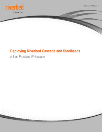
Reinforced Load Bearing Cantilever TableKEY TO TABLE0 No Reinforcement RequiredBCI JoistsRoofJoistTrussDepth Joist Span[in] Series SWS1X000000WSWS1000000WSWS10000000010000000001. Cut 48" long reinforcers to match the joistdepth. Use min. 23/32" plywood/OSB-ratedsheathing, Exposure 1, 48/24 Span Ratingpanels. The face grain must be horizontal(measure the 48" dimension along the longedge of the panel).2. Fasten the reinforcer to the joist flanges with8d nails at 6" o.c. When reinforcing both sides,stagger the nails to avoid splitting the joist flanges.Roof Total Load [psf]45Joist Spacing X11XXXXXXX0
camber) and no shrinkage related call backs. Boise Cascade Rimboard Boise Cascade Engineered Wood Products offer several engineered rimboard products regionally, including BC RIM BOARD OSB, VERSA RIM , VERSA STRAND 0.8 and VERSA LAM 1.4 1800 (check supplier or Boise Cascade EWP rep for availability). These