Transcription
MAKING MODERN LIVING POSSIBLEwww.danfoss.com/drivesVLTp AQUA DriveCascade Controller Options MCO 101/102Operating Instructions130R0345MI38C402*MI38C402*Rev. 2012-08-21
VLT AQUA Drive MCO 101/MCO 102SafetySafetyWARNINGSymbolsThe following symbols are used in this manual.HIGH VOLTAGEFrequency converters contain high voltage whenconnected to AC mains input power. Qualified personnelonly should perform installation, start up, andmaintenance. Failure to perform installation, start up,and maintenance by qualified personnel could result indeath or serious injury.WARNINGIndicates a potentially hazardous situation which couldresult in death or serious injury.CAUTIONIndicates a potentially hazardous situation which canresult in minor or moderate injury. It can also be used toalert against unsafe practices.WARNINGUNINTENDED STARTWhen the frequency converter is connected to AC mains,the motor may start at any time. The frequencyconverter, motor, and any driven equipment must be inoperational readiness. Failure to be in operationalreadiness when the frequency converter is connected toAC mains could result in death, serious injury,equipment, or property damage.WARNINGCAUTIONIndicates a situation that could result in equipment orproperty-damage-only accidents.NOTICEIndicates highlighted information to regard withattention to avoid mistakes or operate equipment at lessthan optimal performance.DISCHARGE TIMEFrequency converters contain DC-link capacitors that canremain charged even when the frequency converter isnot powered. To avoid electrical hazards, disconnect ACmains, any permanent magnet type motors, and anyremote DC-link power supplies, including battery backups, UPS, and DC-link connections to other frequencyconverters. Wait for the capacitors to fully dischargebefore performing any service or repair work. Theamount of wait time is listed in the Discharge Time table.Failure to wait the specified time after power has beenremoved before doing service or repair could result indeath or serious injury.Voltage[V]ApprovalsNOTICEThe T7 (525-690 V) frequency converters are not certifiedfor UL.Minimum Waiting Time (Minutes)415200-2400.25-3.7kW5.5-45 kW380-4800.37-7.5kW11-90 kW525-6000.75-7.5kW11-90 kW525-69011-37 kW2030110-250kW45-400kW40315-1000kW450-1200kW1400 kWHigh voltage may be present even when the warningLED display lights are off.Discharge TimeMI38C402 - VLT is a registered Danfoss trademark
SafetyVLT AQUA Drive MCO 101/MCO 102MI38C402 - VLT is a registered Danfoss trademark
VLT AQUA Drive MCO 101/MCO 102ContentsContents1 Introduction31.1 Purpose of these Operating Instructions1.1.1 Software Version332 Application Types52.1 Overview52.2 Supported Configurations52.2.1 Extension of Basic Cascade - Parameter Group 25** Control Mode52.2.2 Master-Follower Configuration72.2.3 Mixed Pump Configuration82.2.3.1 Unequal Size Pump Configuration82.2.3.2 Mixed Pump Configuration with Alternation92.2.4 Using Soft Starters for Fixed Speed Pumps2.3 Sleep Mode10102.3.1 Basic Cascade Controller112.3.2 Master/Follower and Mixed Pump Configurations113 Installation123.1 Mechanical and Electrical Installation123.1.1 Before Start123.1.2 Extended Cascade ControllerMCO 101123.1.3 Advanced Cascade ControllerMCO 102144 Configuring the System4.1 Configuring the Extended and Advanced Cascade Controller16164.1.1 Setting-up the Cascade Parameters164.1.2 Configuration of Multiple Frequency Converters164.1.3 Closed Loop Control174.1.4 Staging/De-staging of Variable Speed Pumps174.1.5 Staging/De-staging of Fixed Speed Pumps174.2 Operation184.2.1 Pump Status and Control184.2.2 Manual Pump Control184.2.3 Runtime Balancing194.2.4 Pump Spin for Unused Pumps194.2.5 Total Lifetime Hours194.2.6 Alternation of the Lead Pump194.2.7 Staging/De-staging in Mixed Pump Configurations204.2.8 Override Staging/De-staging20MI38C402 - VLT is a registered Danfoss trademark1
VLT AQUA Drive MCO 101/MCO 102Contents4.2.9 Minimum Speed De-staging204.2.10 Fixed Speed only Operation204.2.11 Flow Compensation for Applications with Cascade Controller215 Parameter Descriptions5.1 Cascade Controller Parameters225.1.1 Cascade CTL Option, 27-**245.1.3 Control & Status, 27-0*255.1.4 Configuration, 27-1*265.1.5 Bandwidth Settings, 27-2*265.1.6 Staging Speed, 27-3*285.1.7 Staging Settings, 27-4*295.1.8 Alternation Settings, 27-5*305.1.9 Digital Inputs, 27-6*315.1.10 Connections, 27-7*355.1.11 Readouts, 27-9*365.2 Parameter Lists375.2.1 25-** Cascade Controller375.2.2 27-** Cascade CTL Option386 Configuration Examples416.1 Master/Follower416.1.1 Basic Settings416.1.2 Master Drive Settings416.1.3 Follower Drive Settings42Index22243MI38C402 - VLT is a registered Danfoss trademark
VLT AQUA Drive MCO 101/MCO 102Introduction1 Introduction1.1 Purpose of these Operating InstructionsThe purpose of these operating instructions is to describethe Danfoss Cascade Controller Options MCO 101 andMCO 102.The operating instructions contain information about: Application typesInstallationConfiguring the systemParametersConfiguration examplesThese operating instructions are intended for use byqualified personnel. Read these operating instructions infull in order to use the Cascade Controller Options safelyand professionally and pay particular attention to thesafety instructions and general warnings. Built-in Basic Cascade Controller (standardCascade Controller) MCO 101 (Extended Cascade Controller)1 1MCO 102 (Advanced Cascade Controller)For further information, see 2 Application Types.The Extended Cascade Controller can be used in twodifferent modes: with the extended features controlled byparameter group 27-** to extend the number of available relays for theBasic cascade controlled by parametergroup 25-**With MCO 101, a total of 5 relays can be used for cascadecontrol and with MCO 102, a total of 8 pumps can becontrolled. The options are able to alternate the leadpump with 2 relays per pump.NOTICE1.1.1 Software VersionExtended Cascade Controller Option forVLT AQUA DriveSoftware version: 1.9xIf MCO 102 is installed, the relay option MCB 105 canextend the number of relays to 13.ApplicationCascade control is a common control system used tocontrol parallel pumps or fans in an energy efficient way.Table 1.1 Software VersionNOTICEMCO 101/102 is software supported from version 1.24onwards.1.1.2 Cascade ControlThe Cascade Controller consists of an option boardcontaining 3 relays that is installed in option slot B. Onceoptions are installed the parameters needed to support theCascade Controller functions will be available through thecontrol panel in parameter group 27-**.MCO 101 and 102 are add-on options extending thesupported number of pumps and the functionalities of thebuilt-in Cascade Controller in the VLT AQUA Drive.The following options for cascade control are available forthe VLT AQUA Drive:The Cascade Controller option enables control of multiplepumps configured in parallel by: Automatically turning individual pumps on/offControlling the speed of the pumpsWhen using Cascade Controllers, the individual pumps areautomatically turned on (staged) and turned off (destaged) as needed in order to satisfy the required systemoutput for flow or pressure. The speed of pumpsconnected to the VLT AQUA Drive is also controlled toprovide a continuous range of system output.Designated useThe Cascade Controller options are designed for pumpapplications, however, it is also possible to use CascadeControllers in any application requiring multiple motorsconfigured in parallel.Operating principleThe Cascade Controller software runs from a singlefrequency converter with Cascade Controller option(master drive). It controls a set of pumps, each controlledMI38C402 - VLT is a registered Danfoss trademark3
1 1IntroductionVLT AQUA Drive MCO 101/MCO 102by a frequency converter or connected to a contactor or asoft starter.Additional frequency converters in the system (followerdrives) do not need any Cascade Controller option card.They are operated in open loop mode and receive theirspeed reference from the master drive. Pumps connectedto follower drives are referred to as variable speed pumps.Pumps connected to mains through a contactor orthrough a soft starter are referred to as fixed speedpumps.Each pump, variable speed or fixed speed, is controlled bya relay in the master drive.The Cascade Controller options can control a mix ofvariable speed and fixed speed pumps.Other resources are available to understand advancedfunctions and programming.4 The VLT AutomationDrive FC 302OperatingInstructions provide details on installation andoperation of the frequency converter. The VLT AutomationDrive FC 302 ProgrammingGuide provides greater detail on working withparameters and many application examples. The VLT AutomationDrive FC 302 Design Guideprovides detailed capabilities and functionality todesign motor control systems. Supplemental publications and manuals areavailable from Danfoss.See mentations/Technical Documentation.htm for listings. Optional equipment may change some of theprocedures described. Reference the instructionssupplied with those options for specificrequirements. Contact the local Danfoss supplieror visit the Danfoss website: mentations/Technical Documentation.htm, for downloads oradditional information.MI38C402 - VLT is a registered Danfoss trademark
VLT AQUA Drive MCO 101/MCO 102Application Types2 Application Types100%100%Relay 10130BA594.122 2Relay 2Relay 12.1 Overview200%200%1 VSP 2 FSPBuiltparameter group 25-** CascadeinController1 VSP 5 FSPMCO parameter group 25-** Cascade101 Controller--1 to 6 VSP 1 to 5 FSP(max. 6 pumps)6 VSPparameter group 27-** CascadeCTL Optionparameter group 27-** CascadeCTL Option1 VSP 8 FSPMCO parameter group 25-** Cascade102 Controller1 to 8 VSP 1 to 7 FSP(max. 8 pumps)8 VSPparameter group 27-** CascadeCTL Optionparameter group 27-** CascadeCTL OptionTable 2.1 Application OverviewVSP Variable Speed Pump (directly connected to the frequencyconverter)FSP Fixed Speed Pump (the motor could be connected viacontactor, soft starter or star/delta starter)2.2 Supported ConfigurationsWhen setting-up the system, create a hardware configuration, which communicates the number of connectedpumps and frequency converters to the master. Thenecessary hardware is explained in the following hardwareconfiguration examples.be used to extend the numbers of relays for cascadecontrol. For instance if a new pump is added to thesystem.Enable the Basic Cascade Controller in 27-10 CascadeController by selecting [3] Basic Cascade Ctrl. Refer to VLT AQUA Drive Programming Guide for further programmingwith parameter group 25-** settings.Illustration 2.1 and Illustration 2.2 show the external wiringneeded for systems with alternating lead pump of 4pumps using basic cascade and MCO 101 as relayextension.2.2.1 Extension of Basic Cascade Parameter Group 25** Control ModeUse of the extended cascade option MCO 101 as anextension of the built-in basic cascade in the frequencyconverterIn applications already controlled by the built-in CascadeController in parameter group 25-**, the option card canMI38C402 - VLT is a registered Danfoss trademark5
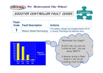
Application TypesVLT AQUA Drive MCO 101/MCO 1022 2Illustration 2.1 Control Circuit Alternating Lead Pump (4 Pumps)Illustration 2.2 Mains Circuit Alternating Lead Pump (4 Pumps)130BA592.12The fixed speed pump configuration provides a costeffective method for controlling up to 9 pumps. It is ableto control system output by controlling the number ofrunning pumps as well as the speed of the single variablespeed pump.In this configuration the VLT AQUA Drive controls onevariable speed pump and up to 8 fixed speed pumps. Thefixed speed pumps are staged and de-staged as neededthrough contactors direct online. The variable speed pumpprovides the finer level of control needed between thestages.The direct online pumps are staged or de-stageddepending on the feedback.6Illustration 2.3 Fixed Speed Pump Configuration ExampleMI38C402 - VLT is a registered Danfoss trademark
VLT AQUA Drive MCO 101/MCO 102Application TypesNOTICE2.2.2 Master-Follower ConfigurationFor the configuration shown in Illustration 2.3, relayselections in parameter group 27-7* Connections are asfollows27-70.0 RELAY 1 [73] Pump 2 to Mains27-70.1 RELAY 2 [74] Pump 3 to Mains27-70.9 RELAY 10 [75] Pump 4 to Mains27-70.10 RELAY 11 [0] Standard Relay27-70.11 RELAY 12 [0] Standard RelayNOTICEPressure fluctuations during staging/de-stagingtransitions may occur and it may be less energy efficientthan the master-follower configurations.MasterwithMCO 101/ 102Follower 1DO 2722The master-follower cascade control mode offers the bestperformance, the most precise control and maximumenergy savings. It controls multiple equal sized pumps inparallel, running all pumps at the same speed and stagesthe pumps on and off according to system requirements.Compared to traditional cascade control the number ofrunning pumps is controlled by speed instead of feedback.To obtain the highest energy saving the stage on and offspeed must be set correctly according to the system. Inthis example terminal 27 of the master drive is used aspulse output for the reference and the terminals 29 of thefollower drives are used as pulse input for this reference.While the master drive is running in closed loop, thefollowers are running in open loop. All follower drives areconnected to mains and motor in the same way as themaster drive.DI 18130BD072.10If the pumps are not equal in size or if 2 relays perpump are used, a Mixed Pump Configuration has to bechosen.Follower 2DI 29DI 18DI 29R1R2T 12T 54DI18T 55T 20StartPU /IPressureTransmitter0 - 10 V0 - 20 mA or4 - 20 mAMotor / Pump 1Motor / Pump 2100%100%Motor / Pump 3100%Illustration 2.4 Basic Wiring Principle (Example)MI38C402 - VLT is a registered Danfoss trademark72 2
In this configuration each pump is controlled by afrequency converter. All pumps and frequency convertersmust be of the same size. Staging and de-staging decisionsare made based on the speed of the frequency converters.The constant pressure is controlled by the master driveoperating in closed loop. The speed will be the same in allrunning pumps with extended control.In the Master/Follower mode, MCO 101 supports up to 6pumps - MCO 102 up to 8 pumps. See 6.1 Master/Followerfor further details.For the configuration shown Illustration 2.4 relayselections in parameter group 27-7* Connections are asfollows:27-70.0 RELAY 1 [1] Drive 2 EnableIllustration 2.5 Example27-70.1 RELAY 2 [2] Drive 3 Enable27-70.9 RELAY 10 [0] Standard Relay27-70.10 RELAY 11 [0] Standard Relay27-70.11 RELAY 12 [0] Standard RelayThe system will automatically runtime balance all pumpsdepending on the pump prioritization made in27-16 Runtime Balancing. The master/follower system willprovide a certain level of redundancy. If the master drivetrips, it will continue to control the follower drives.For this configuration relay selections in parametergroup 27-7* Connections are as follows:27-70.0 RELAY 1 [1] Drive 2 Enable27-70.1 RELAY 2 [74] Pump 3 to Mains27-70.9 RELAY 10 [75] Pump 4 to Mains27-70.10 RELAY 11 [0] Standard Relay27-70.11 RELAY 12 [0] Standard Relay2.2.3.1 Unequal Size Pump Configuration2.2.3 Mixed Pump Configuration130BA594.12Relays set to [0] Std. Relay, can be used as general purposerelays, controlled by parameter group 5-4* Relays.The Unequal Size Pump configuration supports a limitedmix of fixed speed pumps in different sizes. It provides forthe largest range of system output with the smallestnumber of pumps.Relay 10MCB 107 External 24 V DC power supply can be addedto increase the level of redundancy.Relay 2NOTICERelay 12 2VLT AQUA Drive MCO 101/MCO 102Application TypesThis configuration combines some of the benefits of themaster follower configuration with some of the initial costsavings of the fixed speed configuration. It is a goodchoice when the extra capacity of the fixed pumps is rarelyneeded.The mixed pump configuration supports a mix of variablespeed pumps connected to frequency converters as well asadditional fixed speed pumps. The variable speed pumpsare staged on and de-staged first based on frequencyconverter speed. The fixed speed pumps are then stagedon last and de-staged last based on the feedback pressure.NOTICEAll variable speed pumps and frequency converters mustbe the same size. Fixed speed pumps may be of differentsizes.8100%100%200%200%Illustration 2.6 ExampleFor this configuration relay selections in parametergroup 27-7* Connections are as follows:27-70.0 RELAY 1 [73] Pump 2 to Mains27-70.1 RELAY 2 [74] Pump 3 to MainsMI38C402 - VLT is a registered Danfoss trademark
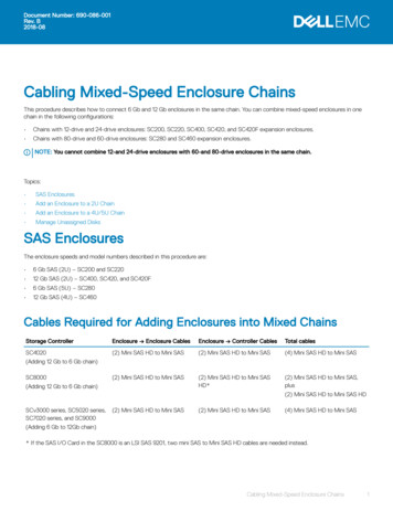
VLT AQUA Drive MCO 101/MCO 10227-70.9 RELAY 10 [75] Pump 4 to Mains27-70.10 RELAY 11 [0] Standard Relay27-70.11 RELAY 12 [0] Standard RelayFor a configuration to be valid, it must be possible tostage pumps in increments of 100% of the size of themaster drive’s variable speed pump. The variable speedpump must control the output between the fixed speedstages, see Illustration 2.7.VariableSpeedFixed Speed100%200%(no control between 100%and 200%)100%100% 300%(no control between 200%100%100% 200% 600%(no control between 400%and 600%)Table 2.3 Invalid Configurations100% is defined as the maximum flow produced by thepump connected to the master drive. The fixed speedpumps must be multiples of this size.CNOTICEOther valid configurations than the ones shown inTable 2.2 are possibleVariable SpeedFixed Speed100%100% 200% (see Illustration 2.7)100%100% 200% 200%100%100% 100% 300%100%100% 100% 300% 300%100%100% 200% 400%100% 100%200%100% 100%200% 200%100%300%130BD073.10100 %300 %100 %100%200%100%100%400 %200 %100%400%Table 2.2 Valid ConfigurationsC2 2and 300%) (see Illustration 2.8)130BD074.10Application Types100 %100%1100%2300 %300 %34Illustration 2.8 Invalid Configuration Example2.2.3.2 Mixed Pump Configuration withAlternationIn this configuration the frequency converter alternatesbetween two pumps and controls the other as additionalfixed speed pump. The Cascade Controller attempts tobalance the running hours of the pumps.100 %100 %100 %1100 %2200 %3200 %4Illustration 2.7 Valid Configuration ExampleNOTICEInvalid configurations, like in Illustration 2.8, will still runbut will not stage on all pumps. This feature allows forlimited operation if a pump fails or is interlocked.MI38C402 - VLT is a registered Danfoss trademark9
Application TypesVLT AQUA Drive MCO 101/MCO 10227-70.11 RELAY 12 [74] Pump 3 to Mains2 2Illustration 2.11 Example 3Pumps 1 and 2 alternate each with 50% of the runninghours. The fixed speed pumps turned on and off asneeded with equal running time between them.Illustration 2.9 Example 1As Illustration 2.9 the two pumps can be ether variablespeed or fixed speed with equal running hours.For this configuration relay selections in parametergroup 27-7* Connections are as follows:27-70.0 RELAY 1 [8] Pump 1 to Drive 1For this configuration relay selections in parametergroup 27-7* Connections are as follows:27-70.0 RELAY 1 [8] Pump 1 to Drive 127-70.1 RELAY 2 [16] Pump 2 to Drive 127-70.9 RELAY 10 [74] Pump 3 to Mains27-70.1 RELAY 2 [16] Pump 2 to Drive 127-70.10 RELAY 11 [75] Pump 4 to Mains27-70.9 RELAY 10 [72] Pump 1 to Mains27-70.11 RELAY 12 [76] Pump 5 to Mains27-70.10 RELAY 11 [73] Pump 2 to Mains27-70.11 RELAY 12 [0] Standard Relay2.2.4 Using Soft Starters for Fixed SpeedPumpsSoft Starters can be used in place of contactors for anyconfiguration using fixed speed pumps.NOTICEMixing Soft Starters and contactors prevents control ofoutput pressure during staging and de-stagingtransitions. Use of soft starters delays staging due to theramp time of the fixed speed pump.2.3 Sleep ModeIllustration 2.10 Example 2With equal running hours for all three pumps, pump 1 and2 can be either variable speed or fixed speed.For this configuration relay selections in group 27-7*Connections are as follows:27-70.0 RELAY 1 [8] Pump 1 to Drive 127-70.1 RELAY 2 [16] Pump 2 to Drive 127-70.9 RELAY 10 [72] Pump 1 to Mains27-70.10 RELAY 11 [73] Pump 2 to Mains10If the load on the system allows for stop of the motor andthe load is monitored, the motor can be stopped byactivating the Sleep Mode function. This is not a normalStop command, but ramps the motor down to 0 RPM andstops energizing the motor. When in Sleep Mode, certainconditions are monitored to find out when load has beenapplied to the system again.Activate Sleep Mode either from the Low PowerDetection/Low Speed Detection or via an external signalapplied to one of the digital inputs (must be programmedvia parameter group 5-1* Digital Inputs). To use forexample an electro-mechanical flow switch to detect a noMI38C402 - VLT is a registered Danfoss trademark
VLT AQUA Drive MCO 101/MCO 102Application Typesflow condition and activate Sleep Mode, the action takesplace at raising edge of the external signal applied(otherwise the frequency converter would never come outof Sleep Mode again as the signal would be steadyconnected).Implementation and configuration of Sleep Mode dependson the hardware configuration and the requirements.2.3.1 Basic Cascade ControllerFor Basic Cascade applications can be used and configuredexactly as it is described for single pump applications inthe Programming Guide. See descriptions of the parametergroups 22-2*, 22-3* and 22-4* for further details.This mode is activated by programming the correspondingspeed in 27-33 Stage Off Speed [RPM] or 27-34 Stage OffSpeed [Hz] respectively.The value for this speed has to be higher than theminimum speed in 4-11 Motor Speed Low Limit [RPM] or4-12 Motor Speed Low Limit [Hz].2 2The value for the override limit in 27-21 Override Limitcauses the frequency converter to wake-up again. Thevalue is entered as a % of the Maximum Reference asprogrammed in 3-03 Maximum Reference.See also 6 Configuration Examples for further details andthe entire description of the required programming stepsfor a Master/Follower application.Low Speed Detection as well as Low Power Detection incombination with the timers for minimum run time,minimum sleep time and the boost feature are supported.The feedback from the pressure transducer is monitoredand when this pressure has dropped with a set percentagebelow the normal set point for pressure (22-44 Wake-upRef./FB Difference), the motor will ramp up again andpressure will be controlled for reaching the set value.2.3.2 Master/Follower and Mixed PumpConfigurationsIn multiple drive applications two different ways of theSleep Mode can be used.It is possible to use the Sleep Mode as it is described forthe Basic Cascade Controller. For this configuration it isessential, that the drive with the cascade controller optionis the last drive running after de-staging. This is achievedby giving the connected pump the highest priority in theparameters for runtime balancing ( e.g. by programmingthe drive with the MCO 101 or the MCO 102 as ”BalancedPriority 1” and all other drives/pumps as ”Balanced Priority2” in 27-16 Runtime Balancing).The other way makes usage of the Stage Off speeds inparameter group 27-3* Staging Speed. This method requiresno special priority settings and therefore allows thebalancing of the running hours for all pumps.In the following example the Sleep Mode in a Master/Follower application is entered at 30 Hz.Stage ON [Hz]Stage OFF [Hz]Stage 1 48.5 (i.e. parameter 2732.1)30 (i.e. parameter 2734.1)Stage 2 48.5 (i.e. parameter 2732.2)40 (i.e. parameter 2734.2)Stage 3 48.5 (i.e. parameter 2732.3)42 (i.e. parameter 2734.3)Table 2.4MI38C402 - VLT is a registered Danfoss trademark11
3 InstallationMax terminal load (AC)240 V AC 2 A3.1 Mechanical and Electrical InstallationMax terminal load (DC)24 V DC 1 AMin terminal load (DC)5 V 10 mA3.1.1 Before StartMax switching rate at rated load/min load6 min-1/20 s-1Table 3.2 Electrical DataNOTICEBefore start, interrupt the power supply to the frequencyconverter. Never install an option card into thefrequency converter during operation.Voltage[V]130BA607.113 3VLT AQUA Drive MCO 101/MCO 102InstallationMinimum Waiting Time (Minutes)4715200-2400.25-3.7 kW5.5-45 kW380-4800.37-7.5 kW11-90 kW525-6000.75-7.5 kW525-6902011-90 kW1.1-7.5 kW11-90 kW3x40090-250 kW3x400110-315 kW3x500110-315 kW3x500132-355 kW3x52575-250 kW3x52590-315 kW3x69090-250 kW3x690110-315 kWMCO1011Illustration 3.1 Mounting of B OptionsHigh voltage may be present even when the warningLED display lights are off.1Table 3.1 Discharge TimeNOTICETable 3.3Export ControlFrom software version 6.72 the output of the frequencyconverter is limited to 590 Hz. Software version 6x.xx is aspecial software for export to countries where speciallegislation for export control applies. In this version theoutput of the frequency converter is also limited to 590Hz, the difference from standard software is that itcannot be flashed, i.e. neither downgraded norupgraded.3.1.2 Extended Cascade ControllerMCO 101The MCO 101 option includes 3 pieces of change-overcontacts and can be fitted into option slot B.12Dismount MCO 101 option to access RS-485 termination(S801) or current/voltage switches (S201, S202)How to add the MCO 101 option:1.Disconnect power to the frequency converter.2.Disconnect power to the live part connections onrelay terminals.3.Remove the LCP, the terminal cover and thecradle from the FC 202.4.Fit the MCO 101 option in slot B.5.Connect the control cables and relief the cablesby the enclosed cable strips.6.Fit the extended cradle and terminal cover.7.Remount the LCP.8.Connect power to the frequency converter.MI38C402 - VLT is a registered Danfoss trademark
VLT AQUA Drive MCO 101/MCO 102InstallationRelay 11Relay 12NC1234567NCNC8910130BA606.10Relay 1012113 38-9mm2mm130BA177.10Illustration 3.2 Usage of ConnectionsIllustration 3.3 Mounting of 3111231112111130BA176.11Do not combine low voltage parts and PELV systems (seeIllustration 3.4.7118910111222Illustration 3.4 Incorrect and Correct Relay Wiring1NC2Live part3PELVTable 3.4 Legend to Correct Relay WiringMI38C402 - VLT is a registered Danfoss trademark13
3.1.3 Advanced Cascade ControllerMCO 102TypeMCF 105The VLT Advanced Cascade Control Card MCO 102 optionis exclusively intended for use in option slot C1. Themounting position of C1 options is shown inIllustration 3.5.Max terminal load (AC)240 V AC 2 AMax terminal load (DC)24 V DC 1 AMin terminal load (DC)5 V 10 mAMax switching rate at rated load/min load6 min-1/20 s-1DescriptionOrdering numberMounting Kit frame size A2and A3 (40 mm for one COption)130B7530OptionsMCF 105Mounting Kit Frame size A5 130B7532MCF 105Mounting Kit Frame size B,C, D, E , F1 and F3 (ExceptB3)130B7533MCF 105Mounting Kit frame size B3(40 mm for one C Option)130B1413Accessory BagMCO 102Accessory Bag130B0152Table 3.5 Electrical Data, MCO 102Table 3.6 Ordering Numbers for Mounting Kits and Accessory BagTools requiredSome items are needed for the installation of a C optionmounting kit (depending on the enclosure):130BA946.103 3VLT AQUA Drive MCO 101/MCO 102InstallationRemoveJ12um13per181927to29activate Safe Sto32p3320Illustration 3.5 Enclosure A2, A3 (and B3) 40 mm (only one C option)14MI38C402 - VLT is a registered Danfoss trademark
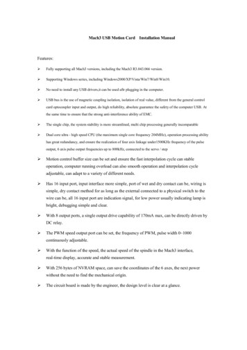
130BA945.10130BB026.11VLT AQUA Drive MCO 101/MCO 102InstallationDCDC3 3Illustration 3.8 Advanced Cascade Controller MCO 102Terminal Connections to the 7 Digital Inputs and Access tothe Internal 24 V DCIllustration 3.6 Enclosures B (except B3) and CHow to add the MCO 102 option1.Disconnect power.2.Disconnect power to the live part connections onrelay terminals.3.Remove the LCP, the terminal cover and thecradle from the FC 202.4.Fit the MCO 102 option in slot C1.5.Connect the control cables and relief the cablesby the enclosed cable strips.6.Fit the extended cradle and terminal cover.7.Remount the LCP.8.Connect power to the frequency converter.130BB025.11Wiring the TerminalsIllustration 3.7 Advanced Cascade Controller MCO 102Terminal Connections, 8 RelaysMI38C402 - VLT is a registered Danfoss trademark15
4 4VLT AQUA Drive MCO 101/MCO 102Configuring the System4 Configuring the System4.1 Configuring the Extended andAdvanced Cascade ControllerThe Extended- and Advanced Cascade Controller can bequickly configured using many of the default parameters.For more information about application types and on howto use advanced features of the Cascade Controlleroptions, see also 2 Application Types.NOTICETo avoid a misconfiguration, check the settings even ifthe parameters have their default values.4.1.1 Setting-up the Cascade Parameters Assign one relay for each follower drive in thesystem Assign the relays for the fixed speed pumps.If it is necessary to have a single frequencyconverter alternate between two pumps, thenassign additional relays.NOTICEAny unused relays will be available for other functionsthrough the parameter group 5-4* Relays.4.1.2 Configuration of Multiple FrequencyConvertersIf more than one frequency converter is used with theCascade Controller the master drive sets the frequency forall frequency converters via a digital signal.Configure the Cascade Controller as follows:1.DOPin 27Select values for the parameters in parametergroup 27-1* Configuration.DIPin 29Parameter Description27-10Cascade Controller can be used to enable or disablethe Extended Cascade Controller. The mixed pumpselection is the general selection for the CascadeController. If using one frequency converter perpump the master-follower configuration can beselected reducing the number of parameters neededto setup the system.27-11Set number of frequency converters27-12Number of pumps - will default to the number offrequency converters.27-14Pump capacity for each pu
MCO 101/102 is software supported from version 1.24 onwards. 1.1.2 Cascade Control The Cascade Controller consists of an option board containing 3 relays that is installed in option slot B. Once options are installed the parameters needed to support the Cascade Controller functions will be a