Transcription
VX126Interlock PCBTECHNICAL MANUALEDITION 1.0
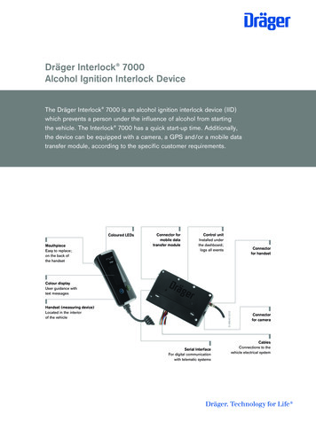
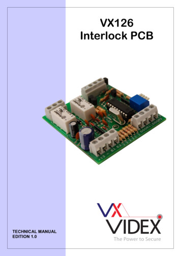
VX126 Interlock PCBDESCRIPTIONThe VX126 is a 2 door interlock PCB which can be extended to more doors by connectingadditional units together by the use of a busy signal. The device requires 2 sets of doorsensors (normally closed) and 2 push to exit buttons (normally open). Two timed drycontact relay outputs allow connectivity for fail safe / fail secure locks and also automaticdoors / gates.The device can be configured to automatically open the opposite door after the first hasclosed by use of the sequential door opening setting, and also de-energise the relaybefore the relay time has elapsed (providing the door has been shut) by use of the followdoor sensor setting.TERMINALSTerminal 12E1E2Door 1Door 1Door 2Door 2ENGCO1NO1NC1CO2NO2NC2Description 12V dc InputGroundPush to exit 1 (Normally open)Push to exit 2 (Normally open)Door contact 1(Normally closed)Door contact 2(Normally closed)Busy SignalCommon (Relay 1)Normally Open (Relay1)Normally Closed (Relay 1)Common (Relay 2)Normally Open (Relay 2)Normally Closed (Relay 2)LOCK RELEASE BACK EMFA capacitor must be fitted across the terminals of an AC lock release and a diode fittedacross the terminals of a DC lock release as shown in the diagrams directly below tosuppress back EMF. - 0.1uF capacitor-12V ACLOCK RELEASEPAGE 2 of 8VX126 Interlock PCBDIODE1N4002 12V DCLOCK RELEASEVER1.0
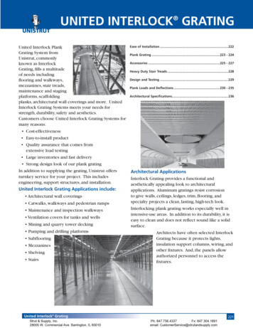
VX126 Interlock PCBDIP SWITCHESThere are four dipswitches located on the VX126. These are used to change the relaytime, sequential door opening and follow door sensor settings.Dip Switch 1ONSequential door openingOFFNormal operationDip Switch 2ONFollow door sensorsOFFNormal operationDip Switch 3 & 4OFF OFF 2.5 SecondsOFF ON5 SecondsONOFF 7.5 SecondsONON10 SecondsNotesSequential door opening – This feature allows the opposite door in use to openautomatically after the current door in use has been closed and the relay time haselapsed. This is monitored using the door contact inputs.Follow door sensors – This feature senses when the door has closed, causing the relay tode-energise before its set time expires.DIMENSIONS / ENCLOSUREPAGE 3 of 8VX126 Interlock PCBVER1.0
VX126 Interlock PCBCOMPONENTSPush to exit buttonsThese must be of the normally open type (push to make).Door SensorsNormally closed door contacts must be used so that the door sensor inputs on the vx126are shorted while the doors are closed.BLOCK DIAGRAMSTECHNICAL SPECIFICATIONWorking voltageStand-by absorptionMax. absorptionWorking temperaturePAGE 4 of 8::::12Vdcapprox. 10mAapprox. 60mA-10 50 ºCVX126 Interlock PCBVER1.0
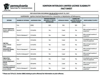
VX126 Interlock PCBWIRING DIAGRAMSPAGE 5 of 8VX126 Interlock PCBVER1.0
VX126 Interlock PCBPAGE 6 of 8VX126 Interlock PCBVER1.0
VX126 Interlock PCBTROUBLESHOOTINGPush to exit button does not operate relay1) Check 12V dc is present across voltage input terminals ( 12 & -)2) Measure dc voltage across both push button inputs (E1 & E2) to GND. Theseshould measure approx. 5V dc in rest and 0V dc when associated push button isactive.3) Ensure both doors are closed and measure dc voltage across both sets of doorsensor inputs (DOOR1 / DOOR2). 0V dc should be present in this state and 5V dcwhile the associated door is opened.4) If 2 or more VX126 interlock PCB’s are part of the same system, measure the ENGterminal to ground. Approx 12V dc should be present when the system is instandby. This will be on when one unit is busy.Relays only operate when doors are in the open position1) Normally open contacts of door sensor in use, switch to normally closed.Push to exit button operates the incorrect door1) Check cabling from both push to exit buttons back to terminals E1 & E2 of theinterlock PCB, and that they are not back to front.When using multiple PCB’s it is possible to activate multiple entrances simultaneously1) Measure the terminal ENG to ground. Approx. 12V dc should be present while thesystem is in standby.2) Check continuity of the ENG cable between VX126 PCB’s.3) If using multiple 12V dc power supplies, ensure a common negative link is present.PAGE 7 of 8VX126 Interlock PCBVER1.0
VX126 Interlock PCBNorthern OfficeVidex Security LtdUnit 4-7 Chillingham Ind. Est.Newcastle Upon TyneNE6 2XXTEL 0870 300 1240FAX 0191 224 5678Southern Office1 OspreyTrinity ParkTrinity WayLondonE4 8TDFAX 0208 523 5825TECHNICAL SUPPORTtech@videx-security.comTEL 0191 224 3174FAX 0191 224 4938http://www.videx-security.comPAGE 8 of 8VX126 Interlock PCBVER1.0
VX126 Interlock PCB PAGE 2 of 8 VX126 Interlock PCB VER1.0 DESCRIPTION The VX126 is a 2 door interlock PCB which can be extended to more doors by connecting additional units together by the use of a busy signal. The device requires 2 sets of door sensors (normally closed) and 2 push to exit buttons (normally open). Two timed dry