Transcription
UTILITIES INFRASTRUCTURE DESIGN – AIMSISSUED FOR CONSTRUCTIONBASIS OF DESIGNMcMurdo Station, AntarcticaSubmitted to:United States Antarctic ProgramLeidos Innovations - Antarctic Support ContractSubmitted by:Merrick & Company5970 Greenwood Plaza Blvd.Greenwood Village, CO 80111Tel: 303-751-0741 Fax: 303-751-2581www.merrick.comJuly 2017
Antarctic Support ContractMcMurdo Station, AntarcticaBasis of Design Document – Utilities Design (AIMS)Contract Number 41N2391183TABLE OF CONTENTS - AIMSSECTION 1EXECUTIVE SUMMARY . 1SECTION 2CIVIL AND SITE WORK . 6SECTION 3STRUCTURAL . 30SECTION 4MECHANICAL AND PLUMBING (FOR BUILDINGS) . 33SECTION 5FIRE PROTECTION. 36SECTION 6ELECTRICAL AND COMMUNICATIONS . 37SECTION 7ARCHITECTURE . 51SECTION 8ENVIRONMENTAL COMPLIANCE . 56SECTION 9APPENDICES . 57APPENDIX 1 – Site PhotographsAPPENDIX 2 – Fire Flow Criteria Determination for Water System Design MemoAPPENDIX 3 - Water Storage Tank Capacity Recommendation MemoAIMSaTable of ContentsJuly 2017
Basis of Design Document – Utilities Design (AIMS)Contract Number 41N2391183Antarctic Support ContractMcMurdo Station, AntarcticaSECTION 1A.EXECUTIVE SUMMARYGeneral1.This Basis of Design (BOD) addresses one element of a major effort by theNational Science Foundation (NSF) to modernize McMurdo Station, its primaryU.S. Antarctic Program (USAP) facility.This modernization effort is entitledAntarctic Infrastructure Modernization for Science (AIMS) and is a multi-year,multi-project effort to upgrade facilities on Station.The overarching goal of thisinfrastructure modernization is to ensure that McMurdo Station remains a viableplatform for supporting Antarctic science for the next 35 to 50 years. The BODpresented here is for the McMurdo Utilities Infrastructure Design Project (Project)and reflects Merrick & Company’s understanding of performance criteria containedin the Project Statement of Work (SOW), augmented by information collected fromMcMurdo Station (Station) user interviews, and Station site investigations. ThisBasis of Design will guide development of construction documents for the Project.2.Work accomplished under this Project’s SOW encompasses activities performed inadvance of AIMS work, as well as the AIMS work itself.The constructiondocuments have been developed as two separate and freestanding designpackages. These packages are entitled “AIMS” and “PreAIMS” and are denotedas such on all construction documents. Narrative in this BOD applies to AIMSefforts only.3.The goals of both this Utilities Infrastructure Design Project and the overarchingAIMS program include:a. Redevelop McMurdo Station into a more energy and operationally efficientcampus, optimized for support of local and deep field science.b. Improve energy consumption and infrastructure support systems.c. Reduce maintenance requirements to the greatest extent possible.d. Provide predictable operational costs and operational efficiencies.e. Offer a reliable, safe and healthy working environment for personnel andvisitors.f.AIMSProvide flexibility to adapt to changing needs of U.S. science in Antarctica.1Executive SummaryJuly 2017
Basis of Design Document – Utilities Design (AIMS)Contract Number 41N2391183Antarctic Support ContractMcMurdo Station, Antarcticag. Reflect the influential presence in Antarctica in a manner consistent with U.Sstature in the international research community.4.Utilities components of AIMS work include:a. Combined domestic and fire suppression water.b. Sanitary sewer.c. Heat loop (hydronic) supply and return.d. Fuel.e. Communications outside plant cabling.f.Power.g. A new water tank with associated appurtenances.h. A new Pump House for water distribution equipment.i.Modification of the existing pump Building 194 and addition of automatic tankvalves in the existing Water Treatment Plant.j.5.New modular telecommunication (Node) facility.Station elements impacted by AIMS construction include:a. Above ground utilidors.b. Direct-bury utility mains in limited locations.c. Concrete culvert utility chases for below ground utilities.d. Improvements to existing surface drainage ways.e. Site grading.f.B.Demolition of existing utility systems as new systems become operational.Project Summary1.The Utilities Infrastructure Design Project includes the design and production ofconstruction documents (drawings, specifications, basis of design narrative, andcalculations) for improved utility distribution systems at McMurdo Station,Antarctica.2.AIMSInformation contained in this AIMS Basis of Design is based upon:2Executive SummaryJuly 2017
Basis of Design Document – Utilities Design (AIMS)Contract Number 41N2391183Antarctic Support ContractMcMurdo Station, Antarcticaa. “McMurdo Station Master Plan” prepared by OZ Architects and Merrick &Company.b. Project meetings, user interviews, design team deployment to McMurdo inFebruary 2016 and February 2017, and other correspondence related to theAntarctic Infrastructure Modernization for Science (AIMS) program.c. Phasing concepts as developed by Leidos and presented to Merrick & Co.d. Leidos meeting and presentation of delineation of work to be performed byLeidos versus work to be bid by and performed by the Ccontractor.3.The design documentation presented herein accommodates AIMS construction toinclude:a. Reconnection of existing buildings to the new exterior fiber optic and copperlines constructed in the pre-AIMS phase.b. Water, sewer, hydronic, fuel, power, and communications service lines tosupport a separate project to develop a Vehicle and Equipment OperationsCenter (VEOC) and a temporarily coincident General Contractor (GC) stagingfacility.c. Water, sewer, hydronic, fuel, power, and communications service lines tosupport the AIMS Core Facility project.d. Improvements to the Station water distribution system, existing pump Building194, new water storage tank, and new Pump House to support fire flowaugmentation.C.Delineation of WorkThe McMurdo Utilities Infrastructure Design Project includes designs for work which willbe executed by Leidos Innovations Corporation. Such designs are presented as part ofthe contract documents in order to facilitate coordination, cooperation and collaborationbetween the Contractor and Leidos, but are not part of the Contractor’s scope of work.Information contained in this AIMS basis of design document applies to both Contractorperformed work and Leidos performed work. Reference AIMS drawing packages fordelineation of efforts information.AIMS3Executive SummaryJuly 2017
Basis of Design Document – Utilities Design (AIMS)Contract Number 41N2391183Antarctic Support ContractMcMurdo Station, AntarcticaD.Stakeholder Interviews and ResultsA major effort was coordinated to solicit input from the wide range of parties withactivities associated with the Station. This effort primarily took the form of a series ofcharrettes, each focused on a major “community” (e.g., grantees, logistics andoperational senior managers, tenant government agencies).A summary of thecharrettes is contained in the report “Design Charrette Meeting Minutes” produced bythe Antarctic Support Contract, led by Lockheed Martin at the time and now by LeidosInnovations Corporation. (Any previous reference to Lockheed Martin should now beconsidered Leidos).E.Relevant Codes and Guiding Principles1.The following codes are utilized in the design of the Project.a. International Building Code (IBC) 2015b. International Plumbing Code (IPC) 2015c. International Mechanical Code (IMC) 2015d. International Energy Conservation Code (IECC) 2015e. NFPA 1 – Fire Code 2015f.NFPA 54 – National Fuel Gas Codeg. NFPA 70 - National Electrical Code 2014h. NFPA 70E - Standard for Electrical Safety in the Work Placei.NFPA 90A - Standard for the Installation of Air Conditioning and VentilatingSystemsj.IESNA - Lighting Handbook (10th Edition)k. IESNA RP8 – Roadway Lightingl.IES RP-8-14 - Roadway Lightingm. IEEE C2-2012 - National Electric Safety Coden. IEEE Standard 142-2007 - Recommended Practice for Grounding Industrialand Commercial Power Systems (Green Book)AIMS4Executive SummaryJuly 2017
Basis of Design Document – Utilities Design (AIMS)Contract Number 41N2391183Antarctic Support ContractMcMurdo Station, Antarcticao. IEEE Standard 242-2001 - Recommended Practice for Protection andCoordination of Industrial and Commercial Power Systems (Buff Book)p. IEEE Standard 399 - Recommended Practices for Industrial and CommercialPower System Analysisq. IEEE Standard 399-1997 - Recommended Practice for Power SystemsAnalysis (Brown Book)r.TIA/EIA 568-B.1 - Commercial Building Telecommunications Cabling Standard,2001s. TIA/EIA 569-B - Commercial Building Standard for TelecommunicationsSpaces and Pathways, 2004t.TIA/EIA 606-A - Administration Standard for Commercial TelecommunicationsInfrastructure, 2002u. J-STD-607-A - Commercial Building Grounding and Bonding Requirements forTelecommunications, 2002v. AHRI 1060 - Performance Rating of Air to Air Heat Exchangers for EnergyRecovery Ventilation Equipmentw. AMCA 210 - Laboratory Methods of Testing Fans for Ratingx. ABMA 9 – Load Ratings and Fatigue Life for Ball Bearingsy. ABMA 11 - Load Ratings and Fatigue Life for Roller Bearingsz. ASHRAE Fundamentals - ASHRAE Handbook of Fundamentals 2013aa. ASHRAE Guideline 0 - The Commissioning Process 2013bb. ASHRAE Guideline 1.1 - HVAC&R Technical Requirements for theCommissioning Process, 2007cc. ASHRAE 62.1 - Ventilation for Acceptable Indoor Air Quality 2010dd. AABC MN-1 - National Standards for Testing and Balancing Heating,Ventilating, and Air Conditioning Systemsee. SMACNA 1780 – HVAC Systems Testing, Adjusting and Balancingff. SMACNA 1966 - HVAC Duct Construction Standards Metal and FlexibleAIMS5Executive SummaryJuly 2017
Basis of Design Document – Utilities Design (AIMS)Contract Number 41N2391183Antarctic Support ContractMcMurdo Station, AntarcticaSECTION 2A.CIVIL AND SITE WORKExisting Site and Utilities Description1.McMurdo Station, Antarctica is located on the southwestern tip of Ross Island. TheStation site, as defined for this Project, consists of the area bounded by WinterQuarters Bay on the west, Observation Hill and the Tank Farm on the east,McMurdo Sound on the south, and Fortress Rocks on the north. The Station isapproximately 140 acres, containing buildings, utilities, roadways, and otherinfrastructure to support the National Science Foundation’s (NSF) mission ofscience and exploration through the United States Antarctic Program (USAP).2.The existing exterior utility distribution systems at the Station consist primarily ofindividual and a collection of Arctic pipes on aboveground pipe racks supported bystanchions, with the collective system known also as “utilidor”. Arctic piperepresents the most obvious component of utilities within the Station. Arctic pipe isa system of interior carrier pipe(s) surrounded by heat trace elements, insulationand an outer corrugated metal pipe (CMP) jacket.Individual arctic pipes arecurrently protected from freezing via the use of electric resistive heat tracing.Existing utilidors span the Station site from the Power Plant (Building 196) areanorth to the Vehicle Maintenance Facility (VMF, Building 143) and to the Tank Farmto the east, with systems concentrated on the south side of Scott Base Road.Existing utilidors convey a range of utilities to buildings and facilities, includingpotable water, fire suppression water, seawater, heat distribution loop (hydronic)supply and return, fuel, sanitary sewer, communications, and power. Conventionalutility poles and overhead distribution are also present for communications andpower.3.At some areas, primarily at road crossings, the existing aboveground utilidor systemtransitions to a belowground system to allow vehicle circulation through the Station.These belowground crossings utilize a culvert system to convey the utilities to theother side of the road or obstruction. In a few instances, Arctic pipe systems andmetal conduit are directly buried beneath the soil. In other instances, such as fuellines, outer casing pipes are placed around the interior carrier pipe and then thisdouble-piped system is directly buried beneath the soil.AIMS6Executive SummaryJuly 2017
Basis of Design Document – Utilities Design (AIMS)Contract Number 41N2391183Antarctic Support ContractMcMurdo Station, AntarcticaB.Concept of New Utilities System1.With the implementation of the McMurdo Master Plan (MP), Pre-AIMS, and AIMSprojects, a series of new facilities will be constructed to support the NSF’s mission.The primary goal of the new construction to upgrade facilities is to increaseefficiency of operations and the research mission at the Station. Several existingfacilities will be demolished as new facilities are constructed and brought online.NSF’s requirements for the Station’s capabilities will remain the same so allactivities currently supported in the existing Station will be present in the newfacilities, and will be expected to be performed more efficiently. The Station’s utilitynetwork will be modified to meet the new goals and facilities, including removingand replacing elements of the existing utility distribution systems.2.The purpose of this Utilities design is to serve the new facilities as they are broughtonline and to continue services to existing facilities. Some existing facilities willremain in the final Station condition (i.e. after AIMS and MP completion) while otherexisting facilities will continue to support the NSF science mission until they arereplaced by new facilities and subsequently demolished.This Project focuses on the exterior utility distribution systems at the Station; nowork associated with this Project will occur within the existing Station productionfacilities (Power Plant Building 196, Water Treatment Plant Building 198, andWastewater Treatment Plant Building 199 (WWTP)), unless otherwise noted. Thecurrent treated water production, current wastewater loading and treatment, andcurrent power production remain as they are today.3.The routing of new utilities as proposed in this design is based on the currentunderstanding of Pre-AIMS and AIMS construction and facility phasing (see Section1, Part B).4.Merrick & Company established high-level goals in generating this design including:a. Reduction of reliance on heat tracing for primary freeze protection of the waterdistribution system by utilizing heat sourced from the hydronic system.b. Design of looped water distribution system where possible to provideredundancy and more robust infrastructure in case of emergency ormaintenance.AIMS7Civil and Site WorkJuly 2017
Basis of Design Document – Utilities Design (AIMS)Contract Number 41N2391183Antarctic Support ContractMcMurdo Station, Antarcticac. Standardization of systems to reduce spare part inventory (and associatedallocated space) and to reduce the training necessary to maintain systems.d. Reduction of energy usage (e.g., heat loss from outdoor runs of the hydronicloop).e. Efficient planning for location and utility needs associated with both existing andproposed facilities, understanding that some existing facilities will persist wellinto the future and others will only remain active until new facilities allow for theirdemolition.f.Fully supporting new and existing facilities at the end of each constructed phasewithout reliance on future phases to complete a system.g. Eliminating or mitigating potential conflicts between phased facility constructionand existing facilities that need to remain operational.h. Maximizing reliance on gravity for sanitary sewer mains. (New alignments will beplaced at slopes greater than 0.5% prescribed in the IPC.)i.5.Reduction of pedestrian and vehicle conflicts with the utility distribution systems.To the maximum extent possible, this design will incorporate Station utility runs(utilidors) within new facilities.This approach takes advantage of the ambientbuilding heat for the utilities for freeze protection, which lessens heat trace energyneeds. This approach results in a reduction of per-foot cost of piping, since internalutility runs will not need heat trace, insulation, or CMP exterior jacketing. Further,efficiency and safety are gained through the ability to perform maintenance andrepair for a larger portion of the overall utilities network in all weather conditions.6.In locations where utilities cannot be placed within buildings, aboveground utilidors,belowground concrete utility trenches, and direct-bury utility mains (in a small areasupporting the GC Staging Area), are designed in descending order of desirability.a. Aboveground utilidors will look much like the current systems in use at theStation currently, with Arctic piping and cable trays installed on pipe racks andstanchion supports. Some aboveground locations in this Project will install newutility lines on existing utilidors.AIMS8Civil and Site WorkJuly 2017
Basis of Design Document – Utilities Design (AIMS)Contract Number 41N2391183Antarctic Support ContractMcMurdo Station, Antarcticab. A below grade pre-cast concrete utility trench, consisting of a box culvert with aremovable lid, will be a method of conveying underground utilities. The utilitytrench will be composed of pre-cast sections placed at prescribed grades.Depending on location and surrounding grade, the trench will be either partiallyburied or fully buried (primarily at road crossing locations).c. Direct-bury wet utility mains (water and sewer) will be placed to support thetemporary GC Staging Area. Refer to the communications and powerdistribution sections of this document for further information on those utilities.7.For water, sewer, and heat loop systems, Arctic pipe systems with insulation andheat trace (as backup freeze protection) are designed. Communications conduits ina direct-bury application will also have heat trace installed as backup freezeprotection. Pipelines without insulation or heat trace will be the norm for fuel linessince there is no risk of freezing. All Arctic pipe systems are proposed to be CMPjacketed, whether they are aboveground or below. Specific information on eachutility system is further defined in the paragraphs below.8.Sanitary sewer design follows to maximum extent guidance within the InternationalPlumbing Code.a. Pipes slopes are above the minimums dictated in Table 704.1. Althoughaboveground alignments are placed on stanchions following existing grades,changes in slopes are minimized to avoid hydraulic jumps.b. Cleanouts are placed on the sanitary lines to meet the intent of the Code withsections of lines within one hundred feet of a cleanout where possible.Cleanouts are also placed in locations where a horizontal change in directionexceeds forty-five degrees.(continued next page)AIMS9Civil and Site WorkJuly 2017
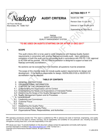
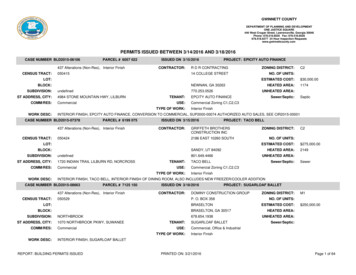
Basis of Design Document – Utilities Design (AIMS)Contract Number 41N2391183Antarctic Support ContractMcMurdo Station, AntarcticaC.Analysis of AIMS Utility NeedsFigure 2.1 Site Plan1.VEOC and GC Staging AreaThe first facility to be constructed as a part of the AIMS project will be the GeneralContractor Staging area (GC Staging Area) or the Vehicle Equipment OperationsCenter (VEOC). The ultimate configuration of this facility is still unknown as it is aDesign-Build project. Per conversations with Leidos, the GC Staging Area will beconstructed initially and the full VEOC facility will be constructed later. Additions tothe GC Staging Area will result in the facility becoming the VEOC.Since the GC Staging Area will be constructed prior to the completion of CoreFacilities (and the new utility mains within), the new GC Staging Area utilities willtie-in to utilities provided by this Project.AIMS10Civil and Site WorkJuly 2017
Antarctic Support ContractMcMurdo Station, AntarcticaBasis of Design Document – Utilities Design (AIMS)Contract Number 41N2391183To this end, a new permanent utilidor will be constructed from the area north ofBuilding 210 and Building 211 (to be demolished by AIMS), extended northeastunder Scott Base Road west of Building 140, and terminate at a location which willserve the fully-completed VEOC facility. The tie-in near Buildings 210 and 211 willbe aboveground and will then transition to a concrete utility trench for crossing ofScott Base Road. North of Scott Base Road, a portion of the utilidor will beaboveground in the Building 140 area and then transition back underground into aconcrete utility trench to the termination for VEOC. From this interim termination,temporary direct-bury utilities will extend southeast to the GC Staging Area. Thesetemporary utilities will ultimately be removed when the full VEOC facility isconstructed.a. VEOC and GC Staging Area Water Supply and DistributionA new 8-inch HDPE carrier pipe (within Arctic pipe system) will connect to theexisting 6-inch bondstrand carrier pipe near Building 210 and will be routedthrough the new utilidor as described above. The line will extend through thepermanent portion of the utilidor and will also contain direct-bury temporarymain to serve the GC Staging Area. In the interim prior to the demolition ofBuilding 211, the existing water service line feeding Building 211 will need tobe reconnected to this new water main.Until Core Facilities and the new water distribution improvements arecompleted, the GC Staging Area and eventually the VEOC will rely on theexisting water distribution system, including the existing high-capacity 1,000gpm pump located in Building 194. Design analysis has indicated the watersystem will not be capable of providing fire flow requirements for the VEOC.To address this shortcoming, a fire water booster pump should be provided inthe VEOC to augment pressure for fire suppression needs in accordance withthe requirements set forth by the VEOC fire protection system designengineer.b. GC Staging Area Sanitary SewerA new 6-inch HDPE carrier pipe (within Arctic pipe system) will connect to theexisting 6-inch bondstrand carrier pipe near Building 210 and will be routedthrough the utilidor as described above. The sewer main will extend throughAIMS11Civil and Site WorkJuly 2017
Antarctic Support ContractMcMurdo Station, AntarcticaBasis of Design Document – Utilities Design (AIMS)Contract Number 41N2391183the permanent portion of the utilidor leading to the GC Staging Area/VEOCsite and will also join water lines in being temporarily direct-buried to serve thesite until VEOC is completed and GC Staging Area functions have ceased. Inthe interim prior to the demolition of Building 211, the existing sewer serviceline associated with Building 211 will need to be reconnected to this newsewer main.c. GC Staging Area Fuel DistributionCurrently, there is no fuel distribution main in the immediate vicinity of the GCStaging Area that could be tapped for building heating needs. In lieu ofconstructing a long service line from an available fuel pipeline, the GC StagingArea will temporarily utilize a local day tank fuel storage tank (not a part of thisProject) until the Core Facilities mains are constructed. In preparation for thefinal configuration, a permanent 2-inch uninsulated steel fuel main will beprovided within the utilidor system described above and will extend from thefuture connection point north of Core Facilities to the permanent VEOCtermination point. These fuel mains will be ready for connection to the finalpermanent configuration when Core Facilities work is completed, but they willremain capped and empty until that time.A separate and distinct element of the existing fuel distribution system willneed to be modified prior to GC Staging Area construction. Due to the gradingactivities associated with site preparation for GC Staging Area /VEOC, theexisting fuel line utilidor east of the 340-series warehouse buildings will needto be relocated further east. This work will be a necessary part of this Project.The new fuel lines will match the existing utilidor configuration, design, andsetup as the system currently in place, an aboveground pipe rack system.d. GC Staging Area Hydronic DistributionSimilar to fuel distribution pipelines, there is no available hydronic tie-in withinthe vicinity of the GC Staging Area. Permanent hydronic supply and returnlines will be installed within the utilidor as described above for fuel, but will notultimately be connected until Core Facilities mains are available. Temporaryhydronic distribution to the GC Staging Area is not necessary since othermethods of heating are available (fuel oil boilers, etc.).AIMS12Civil and Site WorkJuly 2017
Antarctic Support ContractMcMurdo Station, Antarctica2.Basis of Design Document – Utilities Design (AIMS)Contract Number 41N2391183Core FacilitiesThe Core Facilities component of the AIMS portion of the McMurdo Master Planconsists of the Central Services, Emergency Operations, Field Science Support,and Trades buildings. This Project includes new utility systems that will be built tosupport the new Core Facilities and will include water, sewer, fuel, hydronic,power, and communications lines. In keeping with Merrick & Company’s high-levelutility design goals, this Project plans for significant portions of the Station utilitymain distribution system to be routed through the Core Facilities.The Core Facilities project is a separate design-build (D-B) contract and is not apart of this Project. The ultimate configuration of utility mains through the facilitywill be the responsibility of the successful D-B Core Facilities team. This Projectwill route distribution mains to the future building location and accommodate futureconnection points that Core Facilities designers can use in their work.a. Core Facilities Water Supply and DistributionThis Project produces a combined fire suppression and domestic waterdistribution system. The new Station water system will consist of a new waterstorage tank (to meet water reserve levels required for fire suppression needs),a new water Pump House, modifications to existing Building 194 (PumpHouse), new valves in Building 198 (Water Treatment Plant), and a waterdistribution main pipeline to the Core Facilities.A new water storage tank will be built southeast of the existing Building 198and the existing water Pump House Building 194 by this Project. The new tankwill augment the existing water storage tanks within and near Building 198.The four existing tanks provide a total volume of approximately 200,000gallons of reverse osmosis (RO) treated water. For the purposes of this design,a working volume of 180,000 gallons of RO-treated water was used forcalculations to allow for differences in volumes such as tanks not being fullytopped-off. The new water storage tank will provide approximately 70,000gallons of additional capacity, bringing the Station total to approximately250,000 gallons. This total amount of on-hand water will simultaneouslysupport fire suppression needs and uninterrupted provision of drinking waterfor Station personnel. (Refer to the technical memoranda “Fire Flow CriteriaAIMS13Civil and Site WorkJuly 2017
Antarctic Support ContractMcMurdo Station, AntarcticaBasis of Design Document – Utilities Design (AIMS)Contract Number 41N2391183Determination for Water System Design” (July 29, 2016) and “Water StorageTank Capacity Recommendation” (August 9, 2016), both prepared by Merrick& Company, for further information on capacity and storage calculations.) Thenew storage tank is sited to facilitate its operation at the same water levelelevations and system parameters of the existing tanks in Building 198.The new water Pump House will support and augment the existing Stationpumping capacity and distribution system. The new Pump House will contain adiesel-driven 1,500-gpm high-capacity pump to meet fire suppression waterdistribution pressures. It will also house smaller pumps and equipment tosupport recirculation of tempered water in the new water storage tank, theexisting water storage tanks, and within a water loop connecting all storagetanks.The new storage tank and new Pump House will tie-in to the existingdistribution system and will operate in tandem with the existing water storageand pumping facilities. A connection between the new Pump House and theexisting Pump House Building 194 will allow both to draw from the availablewater storage and an output connection from the new Pump House to theoverall distribution system will allow it to supply water to Station facilities.As a part of this Project, the existing 1,000-gpm electric-driven pump inBuilding 194 will be replaced with a new 1,500 gpm electric-driven pump. Thisconfiguration provides an equally capable redundancy as well as powerdiversification (diesel and electric) to allow full-capacity fire suppression waterin the event of an emergency.This Project includes new water distribution mains to connect the new tank andpump systems to the existing distribution system (as described above) andalso directly to the new Core Facilities. An 8-inch HDPE water main carrierpipe (within Arctic pipe) will be provided from the new Pump House area to thesouthwest corner of the Core Facilities.This Project will increase water main capacity between the existing storagetanks in Building 198 and Building 194 by increasing pipe diameter to 10-inchHDPE carr
IEEE Standard 142-2007 - Recommended Practice for Grounding Industrial . IEEE Standard 242-2001 - Recommended Practice for Protection and Coordination of Industrial and Commercial Power Systems (Buff Book) p. IEEE Standard 399 - Recommended Practices for Industrial and Commercial Power System Analysis q.