Transcription
CHAPTER 01PRESENTATION OFTECHNICAL DRAWINGPrepared by: Sio Sreymean2015-2016
Why do we need to study this subject?
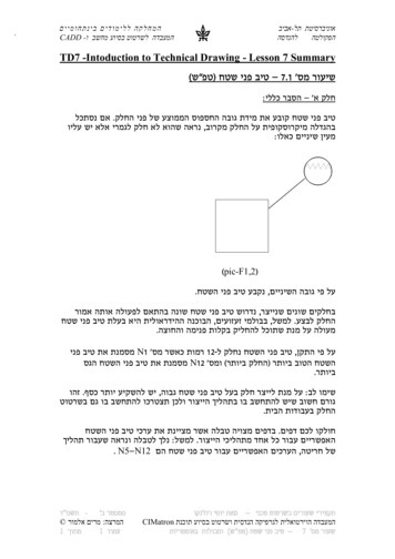
Effectiveness of Graphics Language1. Try to write a description ofthis object.2. Test your written descriptionby having someone attemptto make a sketch from yourdescription.You can easily understand that The word languages are inadequate for describing thesize, shape and features completely as well asconcisely.Lec. Bhuiyan Shameem Mahmood3
Composition of Graphic LanguageGraphic language in “engineering application” uselines to represent the surfaces, edges and contoursof objects.The language is known as “drawing” or “drafting” .A drawing can be done using freehand, instrumentsor computer methods.Lec. Bhuiyan Shameem Mahmood4
Freehand drawingThe lines are sketched without using instruments otherthan pencils and erasers.ExampleLec. Bhuiyan Shameem Mahmood5
Instrument drawingInstruments are used to draw straight lines, circles, andcurves concisely and accurately. Thus, the drawings areusually made to scale.ExampleLec. Bhuiyan Shameem Mahmood6
Computer drawingThe drawings are usually made by commercial softwaresuch as AutoCAD, solid works etc.ExampleLec. Bhuiyan Shameem Mahmood7
INTRODUCTION An engineering drawing is a type of technicaldrawing, used to fully and clearly definerequirements for engineered items, and is onsforlayout,nomenclature,interpretation, appearance size, etc.Its purpose is to accurately and unambiguouslycapture all the geometric features of a product or acomponent.The end goal of an engineering drawing is toconvey all the required information that will allow amanufacturer to produce that component.8Lec. Bhuiyan Shameem Mahmood
PURPOSE OF AN ENGINEERING DRAWING1. An engineering drawing is not an illustration.2. It is a specification of the size and shape of a part or assembly.3. The important information on a drawing is the dimension andtolerance of all of its features.9Lec. Bhuiyan Shameem Mahmood
Elements of Engineering DrawingEngineering drawing are made up of graphics languageand word language.GraphicslanguageDescribe a shape(mainly).WordlanguageDescribe size, location andspecification of the object.Lec. Bhuiyan Shameem Mahmood10
Basic Knowledge for ctionmethodGeometricconstructionLettering11Lec. Bhuiyan Shameem Mahmood
PROJECTIONMETHOD
PROJECTION aphicMultiview13Lec. Bhuiyan Shameem Mahmood
PROJECTION THEORYThe projection theory is used to graphically represent3-D objects on 2-D media (paper, computer screen).The projection theory is based on two variables:1) Line of sight2) Plane of projection (image plane or picture plane)14Lec. Bhuiyan Shameem Mahmood
Line of sightis an imaginary ray of light between anobserver’s eye and an object.There are 2 types of LOS : parallel and convergeParallel projectionPerspective projectionLine of sightLine of sight15Lec. Bhuiyan Shameem Mahmood
Plane of projection is an imaginary flat plane whichthe image is created.The image is produced by connecting the points wherethe LOS pierce the projection plane.Parallel projectionPerspective projectionPlane of projectionPlane of projection16Lec. Bhuiyan Shameem Mahmood
DISADVANTAGE OFPERSPECTIVE PROJECTIONPerspective projection is notused by engineer for manufacturing of parts, because1) It is difficult to create.2) It does not reveal exactshape and size.Width is distortedLec. Bhuiyan Shameem Mahmood17
ORTHOGRAPHICPROJECTION
Orthographic"comes from theGreek word for "straight writing (ordrawing)." This projection shows theobject as it looks from the front,right, left, top, bottom, or back, andare typically positioned relative toeach other according to the rules ofeither “First Angle” or “Third Angle”projection.ORTHOGRAPHIC PROJECTION19Lec. Bhuiyan Shameem Mahmood
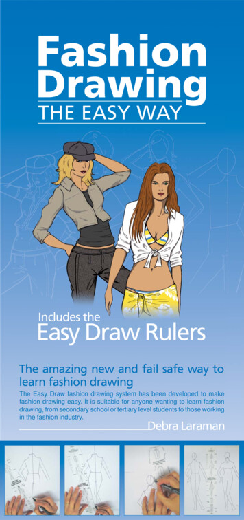
PICTORIAL 3-dimensional representations One-point one vanishing pointlines that are not verticalor horizontal converge tosingle point in distanceTwo-point or Three-point two or three vanishing pointsWith two points, vertical orhorizontal lines parallel, but not both With three-point, no lines are parallelIsometric Drawing shows corner of object,but parallel lines on object areparallel in drawing Shows three dimensions, but novanishing point(s) Lec. Bhuiyan Shameem Mahmood20
One-pointTwo-Point21Lec. Bhuiyan Shameem Mahmood
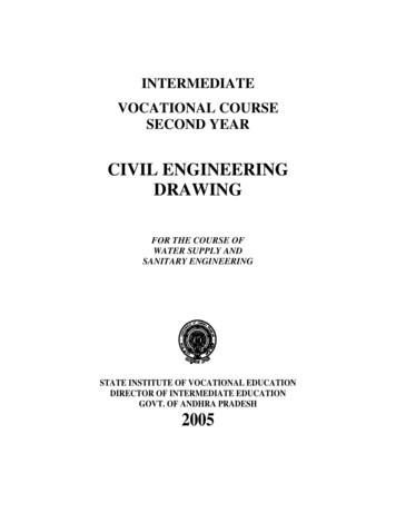
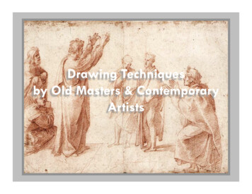
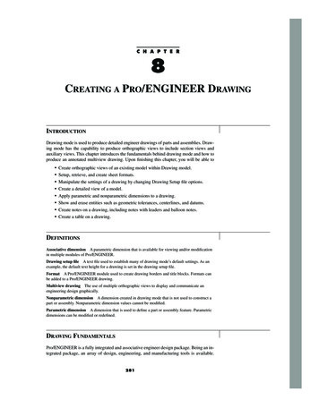
SYMBOLS FOR THIRD ANGLE (RIGHT)OR FIRSTANGLE (LEFT).First angle projection is the ISO standard and is primarily used inEurope. The 3D object is projected into 2D "paper" space as ifyou were looking at an X-ray of the object: the top view isunder the front view, the right view is at the left of the frontview. Third angle projection is primarily used in the United States andCanada, where it is the default projection system according toBS 8888:2006, the left view is placed on the left the top view on22the top. Lec. Bhuiyan Shameem Mahmood
MEANINGOrthographic projection is a parallel projection techniquein which the parallel lines of sight are perpendicular to theprojection planeObject views from top121523 4534Projection plane23Lec. Bhuiyan Shameem Mahmood
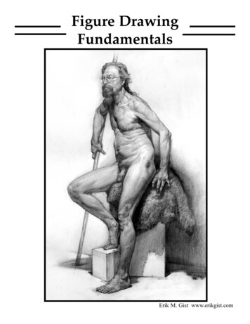
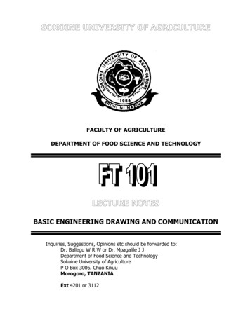
IMAGE OF A PART REPRESENTED IN FIRST ANGLEPROJECTION24Lec. Bhuiyan Shameem Mahmood
Draw object from two / three perpendicular viewsORTHOGRAPHIC / MULTIVIEWWhat it lookslike pictorially/ Orthographic25Lec. Bhuiyan Shameem Mahmood
26Lec. Bhuiyan Shameem Mahmood
27Lec. Bhuiyan Shameem Mahmood
ORTHOGRAPHIC VIEWOrthographic view depends on relative position of the objectto the line of sight.RotateTwo dimensions of anobject is shown.TiltMore than one view is neededto represent the object.Multiview drawingThree dimensions of an object is shown.Axonometric drawingLec. Bhuiyan Shameem Mahmood28
Multiview DrawingAdvantageIt represents accurate shape and size.Disadvantage Require practice in writing and reading.ExampleMultiviews drawing (2-view drawing)29Lec. Bhuiyan Shameem Mahmood
Axonometric (Isometric) DrawingAdvantageEasy to understandDisadvantageShape and angle distortionExampleDistortions of shape and size in isometric drawingCircular holebecomes ellipse.Right angle becomes obtuse angle.30Lec. Bhuiyan Shameem Mahmood
Isometric projection31Lec. Bhuiyan Shameem Mahmood
ISOMETRIC PROJECTION32Lec. Bhuiyan Shameem Mahmood
SECTIONAL VIEWS33Lec. Bhuiyan Shameem Mahmood
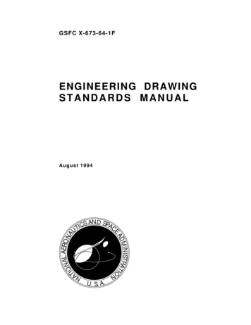
AUXILIARY VIEWS Used to show true dimensions of an inclined plane.34Lec. Bhuiyan Shameem Mahmood
AUXILIARY PROJECTION35Lec. Bhuiyan Shameem Mahmood
AUXILIARY PROJECTION36Lec. Bhuiyan Shameem Mahmood
TRADITIONALDRAWING TOOLS
Drawing board/table.Drawing sheet/paper.Drafting /triangles.Scales.Compass and divider.INSTRUMENTS38Lec. Bhuiyan Shameem Mahmood
DRAWING BOARD39Lec. Bhuiyan Shameem Mahmood
DRAWING TABLE40Lec. Bhuiyan Shameem Mahmood
DRAWING SHEET/PAPER 216 X 280 mm280 X 382 mm382 X 560 mm585 X 726 mm41Lec. Bhuiyan Shameem Mahmood
DRAFTING TAPE42Lec. Bhuiyan Shameem Mahmood
PENCILS Wood pencils: H, 2H, 3H, 4H,5H, 6H, 7H, 8H, 9H, B, HB, 2B,3B, 4B, 5B, 6B.Semiautomatic Pencils (leadholder) are more convenientthen ordinary wood pencils.43Lec. Bhuiyan Shameem Mahmood
ERASER44Lec. Bhuiyan Shameem Mahmood
SHARPENER45Lec. Bhuiyan Shameem Mahmood
T-SQUARE46Lec. Bhuiyan Shameem Mahmood
47Lec. Bhuiyan Shameem Mahmood
48Lec. Bhuiyan Shameem Mahmood
49Lec. Bhuiyan Shameem Mahmood
SET-SQUARES/TRIANGLES50Lec. Bhuiyan Shameem Mahmood
51Lec. Bhuiyan Shameem Mahmood
CIRCLE TEMPLATE52Lec. Bhuiyan Shameem Mahmood
SCALES53Lec. Bhuiyan Shameem Mahmood
COMPASS AND DIVIDER54Lec. Bhuiyan Shameem Mahmood
DRAWINGSTANDARD
INTRODUCTIONStandards are set of rules that govern how technicaldrawings are represented.Drawing standards are used so that drawings conveythe same meaning to everyone who reads them.56Lec. Bhuiyan Shameem Mahmood
Standard CodeFull nameCountryCodeThailandมอก.USAANSIAmerican National Standard InstituteJapanJISJapanese Industrial StandardUKBSBritish StandardAustraliaASAustralian StandardGermanyDINDeutsches Institut für NormungISO57International Standards OrganizationLec. Bhuiyan Shameem ��ผลิตภัณฑ์อตุ สำหกรรม
Partial List of Drawing StandardsContentsCode numberJIS Z 8311Sizes and Format of DrawingsJIS Z 8312Line ConventionsJIS Z 8313LetteringJIS Z 8314ScalesJIS Z 8315Projection methodsJIS Z 8316Presentation of Views and SectionsJIS Z 8317Dimensioning58Lec. Bhuiyan Shameem Mahmood
DRAWING SHEETTrimmed paper ofa size A0 A4.A4A3Standard sheet size(JIS)A4A3A2A1A0210 x 297297 x 420420 x 594594 x 841841 x 1189(Dimensions in millimeters)A2A1A0Lec. Bhuiyan Shameem Mahmood59
Orientation of drawing sheet1. Type X (A0 A4)c2. Type Y (A4 only)ddDrawing spaceBorderlinescDrawingspaceTitle blockcTitle blockSheet sizeA4A3A2A1A0Lec. Bhuiyan Shameem Mahmoodc (min) d (min)1025102510252025202560
Drawing ScalesLength, sizeScale is the ratio of the linear dimension of an elementof an object shown in the drawing to the real lineardimension of the same element of the object.Size in drawingActual size:Lec. Bhuiyan Shameem Mahmood61
Drawing ScalesDesignation of a scale consists of the word “SCALE”followed by the indication of its ratio, as followSCALE 1:1for full sizeSCALE X:1 for enlargement scales (X 1)SCALE 1:X for reduction scales(X 1)Dimension numbers shown in the drawing are correspondto “true size” of the object and they are independent ofthe scale used in creating that drawing.62Lec. Bhuiyan Shameem Mahmood
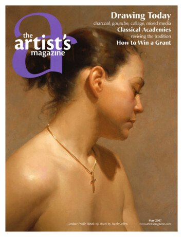
Basic Line TypesTypes of LinesAppearanceName accordingto applicationContinuous thick lineVisible lineContinuous thin lineDimension lineExtension lineLeader lineDash thick lineHidden lineChain thin lineCenter lineNOTE : We will learn other types of line in later chapters.Lec. Bhuiyan Shameem Mahmood63
Meaning of LinesVisible lines represent features that can be seen in thecurrent viewHidden lines represent features that can not be seen inthe current viewCenter linerepresents symmetry, path of motion, centersof circles, axis of axisymmetrical partsDimension and Extension lines indicate the sizes andlocation of features on a drawing64Lec. Bhuiyan Shameem Mahmood
TYPES OF LINE65Lec. Bhuiyan Shameem Mahmood
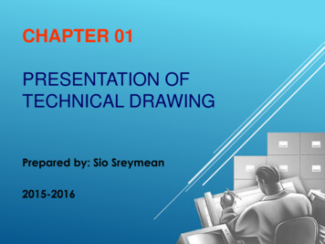
LINE CONVENTIONS Visible Lines – solid thick lines that represent visible edges or contours Hidden Lines – short evenly spaced dashes that depict hidden features Section Lines – solid thin lines that indicate cut surfaces Center Lines – alternating long and short dashes Dimensioning Dimension Lines - solid thin lines showing dimension extent/direction Extension Lines - solid thin lines showing point or line to which dimensionapplies Leaders – direct notes, dimensions, symbols, part numbers, etc. to featureson drawing Cutting-Plane and Viewing-Plane Lines – indicate location of cutting planes forsectional views and the viewing position for removed partial views Break Lines – indicate only portion of object is drawn. May be random“squiggled” line or thin dashes joined by zigzags. Phantom Lines – long thin dashes separated by pairs of short dashes indicatealternate positions of moving parts, adjacent position of related parts andrepeated detail Chain Line – Lines or surfaces with special requirementsLec. Bhuiyan Shameem Mahmood66
Viewing-plane line2Extensionline3DimensionLineCenter Line5Hidden Line6Break Line7Cutting-plane Line8Visible Line910Center Line (of motion)LeaderPhantom14LineSection Line12SECTIONA-ALec. Bhuiyan Shameem Mahmood11VIEW B-B67
HIJKLMNOPQRSTUVWXYZABCD
TEXT ON DRAWINGSText on engineering drawing is used :To communicate nongraphic information.As a substitute for graphic information, in those instancewhere text can communicate the needed informationmore clearly and quickly.Thus, it must be written withLegibility- shape- space between letters and wordsUniformity- size- line thicknessLec. Bhuiyan Shameem Mahmood69
ExamplePlacement of the text on drawingDimension & NotesTitle BlockNotesLec. Bhuiyan Shameem Mahmood70
LETTERING STANDARDANSI StandardThis courseUse a Gothic text style,Use only a vertical Gothiceither inclined or vertical.text style.Use all capital letters.Use both capital andlower-case letters.Use 3 mm for mostSame. For letters in titletext height.block it is recommend to use5 8 mm text heightSpace between linesN/A.of text is at least 1/3Follows ANSI rule.of text height.Lec. Bhuiyan Shameem Mahmood71
BASIC STROKESStraightSlantedHorizontalCurvedExamples : Application of basic stroke“I” letter1“A” letter 12“B” letter 1433Lec. Bhuiyan Shameem Mahmood25672
Suggested Strokes SequenceUpper-case letters & NumeralsStraight linelettersCurved linelettersCurved lineletters &Numerals73Lec. Bhuiyan Shameem Mahmood
Suggested Strokes SequenceLower-case lettersThe text’ s body height is about 2/3 the height of a capitalletter.Lec. Bhuiyan Shameem Mahmood74
STROKE SEQUENCETLIEFH75Lec. Bhuiyan Shameem Mahmood
STROKE SEQUENCEVXW76Lec. Bhuiyan Shameem Mahmood
STROKE SEQUENCEMKNYAZ477Lec. Bhuiyan Shameem Mahmood
STROKE SEQUENCEOQCG78Lec. Bhuiyan Shameem Mahmood
STROKE SEQUENCEDUPBRJ1279Lec. Bhuiyan Shameem Mahmood
STROKE SEQUENCE5780Lec. Bhuiyan Shameem Mahmood
STROKE SEQUENCE03S86981Lec. Bhuiyan Shameem Mahmood
Stroke Sequenceli82Lec. Bhuiyan Shameem Mahmood
vStroke Sequencewxkz83Lec. Bhuiyan Shameem Mahmood
jStroke Sequenceyftr84Lec. Bhuiyan Shameem Mahmood
cdStroke SequenceoabpqLec. Bhuiyan Shameem Mahmoode85
gStroke Sequencenmhus86Lec. Bhuiyan Shameem Mahmood
Word CompositionLook at the same word
Isometric Drawing shows corner of object, but parallel lines on object are parallel in drawing Shows three dimensions, but no vanishing point(s) 20 Lec. Bhuiyan Shameem Mahmood. One-point Two-Point 21 Lec. Bhuiyan Shameem Mahmood. SYMBOLS FOR THIRD ANGLE (RIGHT)OR FIRST ANGLE (LEFT). First angle projection is the ISO standard and is primarily used in Europe. The 3D object is