Transcription
Design & Engineering ServicesPerformance Evaluation of Trane VoyagerDualCool in a Large Retail Mall - Phase 1HT.12.SCE.002 ReportPrepared by:Design & Engineering ServicesCustomer Service Business UnitSouthern California EdisonDecember 2012
Large Retail Mall Field Demonstration of Trane DualCool - Phase 1HT.12.SCE.002AcknowledgementsSouthern California Edison’s Design & Engineering Services (DES) group is responsible forthis project. It was developed as part of Southern California Edison’s HVAC TechnologySystem Diagnostics Advocacy Program (HTSDA) under internal project numberHT.12.SCE.002. Youndy Hung conducted this technology evaluation with overall guidanceand management from Jerine Ahmed. For more information on this project, contactyoundy.hung@sce.com.DisclaimerThis report was prepared by Southern California Edison (SCE) and funded by Californiautility customers under the auspices of the California Public Utilities Commission.Reproduction or distribution of the whole or any part of the contents of this documentwithout the express written permission of SCE is prohibited. This work was performed withreasonable care and in accordance with professional standards. However, neither SCE norany entity performing the work pursuant to SCE’s authority make any warranty orrepresentation, expressed or implied, with regard to this report, the merchantability orfitness for a particular purpose of the results of the work, or any analyses, or conclusionscontained in this report. The results reflected in the work are generally representative ofoperating conditions; however, the results in any other situation may vary depending uponparticular operating conditions.Southern California EdisonDesign & Engineering ServicesDecember 2012
Large Retail Mall Field Demonstration of Trane DualCool - Phase 1HT.12.SCE.002EXECUTIVE SUMMARYThe Western Cooling Challenge (WCC) is a program managed by UC Davis’ Western CoolingEfficiency Center (WCEC) that focuses on advancing commercial development and marketintroduction of rooftop-packaged air conditioners that are optimized for the hot-dry climatesof the Western United States. The WCC requires 40% energy savings while operating atpeak design conditions, compared to equipment that meets current federal minimumequipment efficiency requirements. One of the first products introduced to the WCC is theTrane Voyager Dual Cool (DC) unit. The explicit goal of this Phase 1 report is to describe thetechnology involved, and document the installation issues for two Trane Voyager DC units ata large retail mall in Ontario, California.The Trane Voyager DC is a hybrid rooftop packaged air conditioner that combines aconventional vapor compression cooling system with a unique evaporative cooling process.This process cools both condenser-air flow, and ventilation airflow, without adding anymoisture to the space. The system can provide space cooling with the evaporativecomponents operating alone, and can cycle two compressor stages to provide added coolingcapacity as needed. This technology provides energy savings as follows: Allows the compressor to operate with a lower compression ratio by providing coolerair to the vapor compression condenser Reduces load on the vapor compression evaporator by cooling the system’s freshventilation air.The sequence of operations includes an “enhanced economizer” mode where the outside airtemperature range for effective economizer operation can be extended due to the addedcapacity of the indirect evaporative cooling for the ventilation air.In addition to field testing, SCE tested the Trane Voyager DC earlier this year, and it metthe performance criteria of at least 40% peak energy savings. Scrutiny of the laboratoryobservations also indicates that there is still room for moderate performance improvements.Some of the efficiency measures are already added by the manufacturer and will beevaluated through this study and others. These measures include variable speed supply fanoperation for savings at part capacity operation and during continuous ventilation periods,and micro channel heat exchangers for improved condenser heat transfer effectiveness.Field-testing also allows real-world confirmation of the results found in the laboratorytesting.Installation of data logging equipment occurs in the first quarter of 2013 to allow datacollection during the peak cooling months. Once sufficient data is collected and assimilated,researchers will write a Phase 2 follow-up report to outline results, conclusions, andrecommendations.Southern California EdisonDesign & Engineering ServicesPage iDecember 2012
Large Retail Mall Field Demonstration of Trane DualCool - Phase 1HT.12.SCE.002ACRONYMScfmCubic feet per minutecmprsrCompressorDCDualCoolTMDESDesign & Engineering ServicesDOEDepartment of EnergyDXDirect ExpansionEEREnergy Efficiency RatiokBtu/hOne Thousand British Thermal Units per hourMafrManufacturerMCAMinimum Circuit AmpacityOSAOutside AirSCESouthern California EdisonTOSAOutside Air TemperatureTROOM-TSPRoom Temperature minus Setpoint TemperatureV/ø/hz/Voltage/phase/HertzWCECUC Davis Western Cooling Efficiency CenterSouthern California EdisonDesign & Engineering ServicesPage iiDecember 2012
Large Retail Mall Field Demonstration of Trane DualCool - Phase 1HT.12.SCE.002CONTENTSEXECUTIVE SUMMARY IINTRODUCTION 1BACKGROUND 2ASSESSMENT OBJECTIVES 3TECHNOLOGY/PRODUCT EVALUATION 4Operating Modes . 5TECHNICAL APPROACH/TEST METHODOLOGY 6FIELD TESTING OF TECHNOLOGY 7TEST PLAN 8INSTRUMENTATION PLAN 9Results . 11DISCUSSION 11CONCLUSIONS 12RECOMMENDATIONS 12APPENDIX A – EQUIPMENT SCHEDULES 13APPENDIX B – SITE PHOTOGRAPHS 14Southern California EdisonDesign & Engineering ServicesPage iiiDecember 2012
Large Retail Mall Field Demonstration of Trane DualCool - Phase 1HT.12.SCE.002FIGURESFigure 1.The conceptual air and water flow, and refrigerantpaths for the Trane Voyager DualCool TM. . 4Figure 2. Instrumentation Schematic . 10Figure 3. Photographs of the Baseline System . 14Figure 4. Photographs of the New System . 14TABLESTable 1. Sequence of Operation for Trane Voyager DC . 6Table 2. Test Plan Instrumentation Schedule . 9Table 3. Existing equipment schedule . 13Table 4. Replacement equipment schedule before addingDualCoolTM accessories . 13Southern California EdisonDesign & Engineering ServicesPage ivDecember 2012
Large Retail Mall Field Demonstration of Trane DualCool - Phase 1HT.12.SCE.002INTRODUCTIONThe Western Cooling Challenge (WCC) is an ongoing program administered by the WesternCooling Efficiency Center (WCEC) that encourages HVAC manufacturers to develop andcommercialize climate-appropriate rooftop packaged air conditioning equipment. Adoptingthis program reduces electrical demand and energy use for cooling resources by at least40% in Western climates, compared to Department of Energy (DOE) 2010 standards.Commercial building owners, investor-owned utilities, and HVAC industry stakeholdersrequested the WCC because they recognize the economic value of efficient coolingtechnologies, and are motivated by state and corporate goals for energy and sustainability.The California Public Utility Commission’s Energy Efficiency Strategic Plan gives specificpriority to those who apply the climate-appropriate cooling technologies that are suggestedby the Challenge.The program provides laboratory testing for performance certification of qualifiedequipment, followed by pilot field installations and detailed operating performanceevaluations. In 2012, Trane Inc. submitted the Trane Voyager DualCoolTM (DC) hybridrooftop unit as an entry to the WCC. June 2012 through July 2012, the UC Davis WesternCooling Efficiency Center (WCEC) conducted laboratory testing of the system at the Intertekpsychrometric test facility in Plano, Texas. During the laboratory tests, WCEC and SCEworked closely with several SCE customers to arrange multiple field evaluations of the TraneVoyager DC.WCEC and SCE Design and Engineering Services (DES), collaborated with utility accountexecutives to reach out to customers to discuss the technology of focus for these pilot fieldevaluations, and conduct site visits to consider various buildings as sites for equipmentinstallation. Ultimately, we chose to replace the following units at a large retail mall inOntario, California: A 12.5 ton Trane TCD 151 at a large retail mall in Ontario, California A 15 ton Trane TCD 181 at a large retail mall in Ontario, CaliforniaOutreach to the customer and collaboration between the utility account executive, theinstalling contractor, the manufacturer, DES, and UC Davis WCEC began in early 2012.Following the initial outreach, we spent several months evaluating the site, specifyingequipment, developing a bid for installation, and arranging legal and administrativeconsiderations between SCE and the customer. We placed equipment orders in August2012, and installed and commissioned the systems in October 2012.Monitoring and evaluation of in-field operating performance for each system is planned forthe 2013 cooling season. This Phase 1 report on installation and commissioning of the unitsdocuments all of the relevant details for the project in 2012, including the plannedinstrumentation plan for deployment.Southern California EdisonDesign & Engineering ServicesPage 1December 2012
Large Retail Mall Field Demonstration of Trane DualCool - Phase 1HT.12.SCE.002BACKGROUNDTrane’s Voyager DC combines a conventional rooftop packaged air conditioner withDualCoolTM technology. DC is an innovative indirect and direct evaporative cooling strategythat increases cooling capacity and unloads compressor power by reducing the airtemperature at the inlet of both the condenser and evaporator coils. This is done withoutadding any moisture to the conditioned space. DC components can be added onto a newHVAC unit, or retrofitted onto an existing unit.The system can provide space cooling with the evaporative components operating alone,and can cycle two compressor stages to provide added cooling capacity as needed. Thetechnology achieves energy savings in the following ways: Allows the compressor to operate with a lower compression ratio by providing coolerair to the vapor compression condenser Reduces load on the vapor compression evaporator by cooling the system’s freshventilation air.The sequence of operations incudes an “enhanced economizer” mode where the outside airtemperature range for effective economizer operation is extended due to the added capacityof the indirect evaporative cooling for the ventilation air.The commercially available system incorporates the following standard or optional features: Staged compressor operation Variable speed control for the supply blower and condenser fans Thermostatic expansion valves Micro-channel condenser heat exchangers Integrated comparative economizer controls Demand control ventilationSouthern California EdisonDesign & Engineering ServicesPage 2December 2012
Large Retail Mall Field Demonstration of Trane DualCool - Phase 1HT.12.SCE.002ASSESSMENT OBJECTIVESThe goals of this field assessment are as follows: Assess the performance and efficiency of installing two Trane Voyager DC HVAC unitsat a large retail mall. Measure the electrical energy and electric demand savings provided by directevaporative pre-cooling the condenser air intake of an RTU, and indirect evaporativecooling of the supply air. Measure the water usage of an evaporatively pre-cooled condenser air system. Measure the effects of operating the DC technology on the management and securityoffice area of a large retail mall. Observe the water conditions in the DC system, including but not limited to, scalebuild-up and algae growth.Southern California EdisonDesign & Engineering ServicesPage 3December 2012
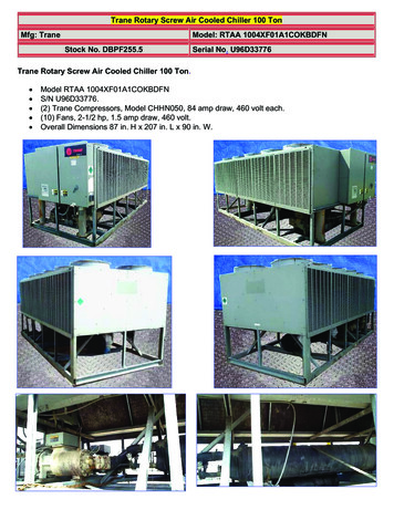
Large Retail Mall Field Demonstration of Trane DualCool - Phase 1HT.12.SCE.002TECHNOLOGY/PRODUCT EVALUATIONFigure 1 shows the conceptual air flow, water flow, and refrigerant paths for the TraneVoyager DC.FIGURE 1.THE CONCEPTUAL AIR AND WATER FLOW, AND REFRIGERANT PATHS FOR THE TRANE VOYAGERTMDUALCOOL .The equipment configuration is shown in Figure 1 as follows:a. Hot, dry outside air is drawn through a fluted cellulose media evaporative cooler locatedat the inlet of the vapor compression condenser coil. Water is delivered through amanifold at the top of the media, and flows through the fluted channels in contact withairflow. The air and water are both cooled by evaporation, and excess water drains bygravity to a stainless steel sump.b. Cool, moist air is drawn across the condenser coils for two separate refrigerant circuits,and afterward, exhausted from the equipment through two condenser fans. Whenoperating in a vapor compression mode, heat is rejected to this airstream, but the fanscan also operate independent of the compressors to cool water. The condenser fansdraw from a single plenum, so both fans must operate together to draw airflow. Thecondenser fans are variable speed, and controlled to draw a different airflow rate foreach mode of operation.c. Water that drains from the evaporative cooler is collected in a sump, and then circulatedthrough a water coil located at the ventilation air inlet to cool fresh air for the buildingSouthern California EdisonDesign & Engineering ServicesPage 4December 2012
Large Retail Mall Field Demonstration of Trane DualCool - Phase 1HT.12.SCE.002before it crosses the vapor compression evaporator. When the pump is activated, waterflows at a constant speed and warms through the heat exchanger before returning tothe evaporative cooler.d. The ventilation airflow path is physically separated from the return air path until after itpasses through the evaporator coil. When the system operates in an economizer modewith 100% outside air, flow is restricted to pass across the upper portion of theevaporator coil only. Similarly, when the system operates without ventilation, flowpasses across only the lower portion of the evaporator coil. The two separate refrigerantcircuits are interlaced at the evaporator coil, so that both circuits are presented to eachairflow path, regardless of the operating mode.OPERATING MODESThere are four general modes of operation for the equipment as follows: Ventilation: The supply air blower operates to deliver a mixture of freshoutside air and return air to the space. No cooling is active in this mode ofoperation. Enhanced Economizer: When the outside air temperature is appropriate, thecondenser fans operate at part speed to chill water in the evaporative cooler.Cool water is circulated through the water coil, the supply air blower is active,and then dampers actuate to provide 100% outside air. Indirect & Stage 1 DX: Condenser fans are staged and operate at 60% speedto cool the water and the condenser air. The first stage compressor operatesusing reduced compressor power because the vapor compression circuitoperates with a lower condensing temperature, and reduced load on theevaporator. When outside air temperature is below a factory selectedchangeover set point, dampers actuate to provide 100% outside air or thesystems operate to deliver the minimum ventilation requirement. Indirect & Stage 2 DX: Condenser fans are staged and operate at 90% speedto cool water and condenser inlet air. Both compressors operate with areduced power draw, though the power draw is reduced because of a lowercondensing temperature, and reduced load on the evaporator. When outsideair temperature is below a factory selected changeover set point, dampers willactuate to provide 100% outside air; otherwise, the systems will operate todeliver the minimum ventilation requirement.When the unit is installed in an application that sometimes operates as recirculation,such as during unoccupied periods, the indirect evaporative circuit will not operate inthe last two cooling modes described above. The water pump still cycles to providedirect evaporative condenser air pre-cooling, but the system shifts to 0% outside air.Southern California EdisonDesign & Engineering ServicesPage 5December 2012
Large Retail Mall Field Demonstration of Trane DualCool - Phase 1HT.12.SCE.002TECHNICAL APPROACH/TEST METHODOLOGYWCEC replaced two existing HVAC units with two 12 ½ nominal tonnage high efficiencyTrane Voyager units with the DC system added at the factory. It is anticipated that theDualCoolTM system will provide up to a 50% increase in cooling capacity. The exact amountdepends on ambient air conditions.The manufacturer designed and furnished the DC system. The WCEC furnished, installed,and will operate the monitoring system to measure the performance of the dual-coolingtechnology and the baseline AC system. The monitoring system installation andcommissioning is still in progress and should be completed in the first quarter 2013.Table 1 shows the complete sequence of operation for the Trane system when it wascommissioned for WCC laboratory testing.TABLE 1. SEQUENCE OF OPERATION FOR TRANE VOYAGER DCMODEINDEPENDENT fN/AVentilationOnlyCOMPONENT OPERATIONROUTSIDEAIRBLOWFRACTIONRoom Temp.minusSetpointTemp.(TROOM-TSP)INDOONO 0OFFN/AYES 0Indirect &Stage 1 DX TSPYesIndirect &Stage 2 DX TSPUnoccupiedStage 1CONDENSERCOMPRESSORWATERFANS SPEED(S)PUMP0%OFFOFFOFFONMINOFFOFFOFF 0ONMIN60%1ONYes 2ONMIN90%1&2ON TSPNO 0ON0%60%1OFFUnoccupiedStage 2 TSPNO 2ON0%90%1&2OFFEnhancedEconomizer TSPN/A 0ON100%30%OFFONIndirect &Stage 1 DX TSPN/A 1ON100%60%1ONIndirect &Stage 2 DX TSPN/A 2ON100%90%1&2ONSouthern California EdisonDesign & Engineering ServicesERPage 6December 2012
Large Retail Mall Field Demonstration of Trane DualCool - Phase 1HT.12.SCE.002FIELD TESTING OF TECHNOLOGYThe goal of the test is to find existing standard HVAC units in a variety of applications toreplace with units of the same size and cooling capacity. SCE selected a large retail mall sitewith two units that serve the management office and security office spaces in Ontario,California.SCE selected this location because it has significant times during the cooling season whereconditions are relatively hot and dry. The DC system provides the best results under theseconditions.Another requirement for a site is that each of the units has to serve a discrete, single zone.If multiple units served one zone or area, determining the cooling effectiveness of a giventested unit is too complex. Both of the selected units serve their own discrete zones.The existing units are 15-year-old standard Trane HVAC units. Nothing else in the HVACsystem, such as ducting or controls are changed or modified when the units are replaced. Inaddition, there are no anticipated changes to the occupancy or activity in the spaces duringthe testing phase in 2013.Installation of the Trane Voyager DC units is almost identical to that of a standard HVACunit. The main difference is the requirement that water is piped to the unit, and there mustbe a drain line for purging. Currently, the system does not require any water treatment, sothe water sump must be purged continually to remove built-up minerals from the water.This reduces scaling in the evaporative media.Southern California EdisonDesign & Engineering ServicesPage 7December 2012
Large Retail Mall Field Demonstration of Trane DualCool - Phase 1HT.12.SCE.002TEST PLANSCE will gather data points every minute and automatically send the data to the WCECproject manager via an internet connection. This allows easy data collection, and earlydetection of malfunctioning instrumentation hardware. Electrical consumption, electricaldemand, water consumption, temperatures, humidity, and maintenance issues associatedwith water evaporation will be collected and evaluated.All of the monitoring points and data logging equipment reside in the unit cabinet, exceptfor the water meter, which is a few feet away from the unit on the roof.SCE has detailed drawings of the tested space to use in a simulation model to determine theexpected baseline energy usage. To calculate savings, this usage will be compared to thedata obtained during the 2013 cooling season. In addition, baseline energy use data for theexisting units was gathered for several months in 2012.The test plan is a work in progress. SCE will provide details in the Phase 2 report by the endof 2013.Southern California EdisonDesign & Engineering ServicesPage 8December 2012
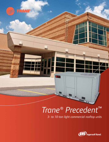
Large Retail Mall Field Demonstration of Trane DualCool - Phase 1HT.12.SCE.002INSTRUMENTATION PLANTable 2 shows the instrumentation plan for this project. This plan is a work in progress andmore data points will be provided in the Phase 2 report at the end of 2013.TABLE 2. TEST PLAN INSTRUMENTATION SCHEDULEMEASUREMENTDEVICEDETAILSNAAltronix VR1TM5 Power conversion module24VAC to 5 VDCTOSAVaisala HUMICAP HMP110-40 F TOSA 176 FRHOSAVaisala HUMICAP HMP1100% RHOSA 100%TRAVaisala HUMICAP HMP110-40 F TOSA 176 FRHRAVaisala HUMICAP HMP1100% RHOSA 100%TSAVaisala HUMICAP HMP110-40 F TOSA 176 FRHSAVaisala HUMICAP HMP1100% RHOSA 100% PSensirion SDP-1000R0.25-4.00 VDCwaterOMEGA FTB4705Pulse OutputdrainOMEGA FTB4705Pulse OutputVECMdataTaker DT85M analog channel0 – 10 VDCVPos DamperdataTaker DT85M analog channel0 or 5 VDCCTcompressor 1NK AT1-005-000-SPAC current transducer to 0-5VDCCTcompressor 2NK AT1-005-000-SPAC current transducer to 0-5VDCCTsump pumpNK AT1-005-000-SPAC current transducer to 0-5VDCT WC inOMEGA T-Type ThermocoupleTaped to inlet pipe andinsulatedTWC outOMEGA T-Type ThermocoupleTaped to outlet pipe & insulatedKWUnit, (also V, A,PF)Dent Powerscout 3Serial connection to dataTakerFigure 2 shows the instrumentation schematic.Southern California EdisonDesign & Engineering ServicesPage 9December 2012
Large Retail Mall Field Demonstration of Trane DualCool - Phase 1COMPRESSOR MP(array)?To TXVDrain460/3ø/60Compressor1460/3ø/60Unit ElectricalDisconnectgpmWATERSumpPumpCT (0-5VDC),120/1ø/6PUMPOSA0TWATER COIL OUTLETMPosΔPDAMPER,AO from UC600TRA,RHRAFIGURE 2. INSTRUMENTATION SCHEMATICSouthern California EdisonDesign & Engineering ServicesTWATER COILINLETWater CoilCT (0-5VDC)Compressor2EvaporatorCOMPRESSOR eCondenser ExhaustAirgpmCondenser460/1ø/60CondenserFans (2)0-10VDC or 4-20mA,VECMHT.12.SCE.002Page 10December 2012
Large Retail Mall Field Demonstration of Trane DualCool - Phase 1HT.12.SCE.002RESULTSSCE will provide results in the Phase 2 report by the end of 2013.DISCUSSIONOverall, the installation and commissioning is successful, especially since the Trane Voyagerbase HVAC units with the added DC components are “off-the-shelf” offerings.Several issues surfaced during the installation process. Recommendations for smootherinstallations are as follows: Pump Control: After the units are commissioned, it is not possible to turn-off thepumps, even under conditions where they should turn off, such as ventilation modeor if the sump is dry. Troubleshooting revealed a programming issue with the onboard UC 600 controller. Re-loading the program resolved the issue. We recommendthat the pump is tested and verified before shipping the unit. Leaking pipe connections: Operation of the DC water system revealed several leaksin the PVC pipe connections and fittings. Roof work associated with the installationhad to be delayed until the leaks were fixed. This issue also occurred on anotherDual Cool RTU retrofit at a big box retailer that may be a systemic issue with partsand/or material. We recommend that the connections and fittings be checked forleaks before leaving the factory. Unit Curbs: One requirement of the DC unit is a higher than normal curb height dueto the dimensions of the water sump, and to allow access to the sump drain plug.Installation was delayed until a curb adapter arrived. It is recommended that themanufacturer provide dimensional data in advance and factor in the additional costsof curb modifications if necessary. Water purging: As described earlier, water is purged (or slowly drained at a constantrate) from the sump to reduce the amount of scaling on the evaporative media. If nopurging were done, the mineral content in the water would rise to a level that woulddamage components. Purging is currently accomplished with a manually operatedball valve on the water drain line. Little guidance was provided as to where to set thevalve. It is recommended that clear rules be provided about how to set the purgerate as a function of average water hardness in the location.SCE will address these items with the manufacturer in future installations.Southern California EdisonDesign & Engineering ServicesPage 11December 2012
Large Retail Mall Field Demonstration of Trane DualCool - Phase 1HT.12.SCE.002CONCLUSIONSSCE will provide conclusions in the Phase 2 report by the end of 2013.RECOMMENDATIONSSCE will provide recommendation details in the Phase 2 report by the end of 2013.Southern California EdisonDesign & Engineering ServicesPage 12December 2012
Large Retail Mall Field Demonstration of Trane DualCool - Phase 1HT.12.SCE.002APPENDIX A – EQUIPMENT SCHEDULESAppendix A provides schedules for the existing equipment and the replacement equipment.Table 3 shows the existing equipment schedule.TABLE 3. EXISTING EQUIPMENT H)CMPRSRNOMINALEER6,00011401782 RECIP105,0009601442 RECIP10V/Ø/HZ/460/3/60460/3/60MCA4032Table 4 shows the replacement equipment schedule before adding the DC accessories.TMTABLE 4. REPLACEMENT EQUIPMENT SCHEDULE BEFORE ADDING M15-15TRANE5,0001140154.292 L5,000960154.292 SCRL12.1460/3/6032Southern California EdisonDesign & Engineering ServicesPage 13December 2012
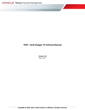
Large Retail Mall Field Demonstration of Trane DualCool - Phase 1HT.12.SCE.002APPENDIX B – SITE PHOTOGRAPHSThis appendix contains site photos taken before and after updating to the new system.FIGURE 3. PHOTOGRAPHS OF THE BASELINE SYSTEMFIGURE 4. PHOTOGRAPHS OF THE NEW SYSTEMSouthern California EdisonDesign & Engineering ServicesPage 14December 2012
The Trane Voyager DC is a hybrid rooftop packaged air conditioner that combines a conventional vapor compression cooling system with a unique evaporative cooling process. . (WCEC) conducted laboratory testing of the system at the Intertek psychrometric test facility in Plano, Texas. During the laboratory tests, WCEC and SCE