Transcription
P1.26GOES-13 END-TO-END INR PERFORMANCE VERIFICATIONAND POST-LAUNCH TESTINGChristopher CarsonBoeing Space & Intelligence Systems, El Segundo CA.James L. Carr, PhDCarr Astronautics, Washington DCChetan SayalNASA Goddard Spaceflight CenterAbstractThe GOES (Geostationary Operational Environmental Satellite) system is thehigh altitude U.S. civilian weather satellite system comprised of an Eastspacecraft over the Atlantic and a West spacecraft over the eastern Pacific plussatellites stored in-orbit. Retired spacecraft are drifted further east over theAtlantic Ocean and put in service to augment coverage of South America.GOES-13, the first of the Boeing GOES N-P series, was launched in May 2006from Cape Canaveral, Florida. Post-Launch Testing (PLT), executed by NASAwith the support of the Boeing team, occurred from June 2006 through GOES-13acceptance in December 2006. GOES-13 is presently stored in orbit. TheGOES N-P series delivers improved Image Navigation and Registration (INR)performance compared to that of the previous generation. This paper describesthe GOES-13 INR verification results from conceptualization through systemacceptance and demonstrates the improved INR capabilities of GOES-13 thatwill ultimately benefit end users.IntroductionGOES-13 is the first in the GOES N-P series of geostationary weather satellite built byBoeing for NASA/NOAA. The GOES N-P INR system design represents an evolution ofthe GOES INR architecture and an infusion of advanced spacecraft pointingtechnologies. Improvements for the N-P series support tighter navigation and frameframe registration requirements. The important innovations for GOES N-P include: Stellar Inertial Attitude Determination (SIAD) for fine attitude determinationOptical Bench accommodations for the Imager and Sounder instrumentsImage Motion Compensation (IMC) implementation improvements1
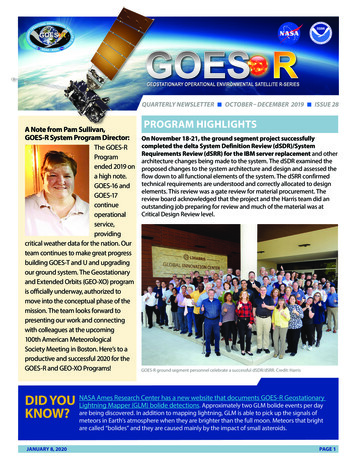
Closed-Loop Dynamic Motion Compensation (DMC) that is added to the IMC tocompensate for residual attitude control errorINR operations to accommodate thruster maneuvers for momentummanagement and station-keepingINR operations for continuous operation across eclipsesINR operations following yaw flipsGOES-13 successfully completed Post-Launch Testing (PLT) and Image Navigationand Registration (INR) Performance Verification in December 2006. This highlysuccessful test program, executed by the NASA/NOAA team tested the GOES-13spacecraft through all normal and special operations, demonstrated INR performance tobe more than 100% improved over the previous generation of GOES satellites and veryclose to next generation (GOES R) performance specifications. End-to-End INRPerformance Verification began in the design phase with pure simulations using a toolcalled the Performance Evaluation System (PES). Closed loop testing followed withhardware-in-the-loop testing using the System Functional Test (SFT) environment andPost-Launch Testing concluded the pre-operational test of the GOES-13 system.INR system functionality and performance testing was performed after the handover ofthe spacecraft to the NASA PLT team following the successful Launch and OrbitRaising (LOR) phase of the mission The PLT sequence was split into two separate testactivities; Activation and Characterization Testing (ACT) and Systems Operation andPerformance Testing (SPOT). During the LOR phase, the spacecraft was inserted intoits geostationary orbit and fully deployed with the functionality of both primary andredundant spacecraft units and all cross-strap configurations verified. At the completionof LOR, NASA assumed responsibility for spacecraft operations and commenced PLTwith the beginning of the ACT. During the ACT phase all activities associated withactivating the Imager/Sounder payload, Solar X-ray Imager (SXI), the SolarEnvironment Monitor (SEM) and the communications and T&C subsystems wereperformed. Additionally, characterizations of the dynamic interactions environment andthe SIAD system, which would disrupt or prevent normal INR operations andassessment of INR performance, were also executed during this phase. Uponcompletion of the ACT phase, the Performance and Operational Testing phase beganwith INR startup and the buildup normal operations typical of a daily operationscadence. During this portion of PLT, the INR system was calibrated and INRspecification testing was performed. Operations through a seasonal yaw flip, eclipseseason, and drift operations were also demonstrated during this time period withoutstanding results.The sequence of testing from launch to spacecraft acceptance is shown in Figure 1-1.A detailed description of events and performance during the INR validation is givenbelow.2
T&C handoverHandover s/c configuration checkStart Imager/Sounder outgassingTurn ON SXI & start outgassingStart onboard schedule (VIS)Imager/Sounder functional PLTScan mirrorcontaminationAvoidance (7 days)Complete SXI outgas(day 3)First visibleImage (day 4)DeployIMP(day 8)SIAD testingEW stationkeepingcycleCooler coverdeploymentINR rapidSuper-rapidscan testFirstSXIimageS/C intrinsic magDipole measurementmaneuversINR startup(start landmarking;INR star observations;GVAR range)Yaw flipcheckoutSMCADITSEM/SXI PLTINR calibrationComm/T&C Payload PLT57NASA/FDF primefor orbit operationsHandovertoNOAASeasonalYaw flipINR INR NOAA StorageSK SRSO Science modeImager/Sounder radiometric calibration & trendingBus/Payload ActivationPre-LaunchLORPre-LaunchBSSBus IOT & Characterization Testing (ACT)ActivitiesActivities0 3NSStationkeeping(cycleInitialization)INR Spec TestINR INR CalImager/Sounder OutgasPLT DayMove s/c em Performance & Operations Testing (SPOT)3628496942145140OATS primefor orbit operations162180169176Eclipse season243289Figure 1-1. Activity Phases for Post Launch TestingINR Design FeaturesGOES-13 INR spacecraft system design represents a marked change from the previousgeneration of weather spacecraft. The spacecraft features a new attitude controlsystem approach which was motivated by tighter INR system accuracy requirements.This section highlights the key upgrades of the INR system for GOES-13 seriesspacecraft.Stellar Inertial Attitude Determination (SIAD)GOES-13 features a stellar inertial attitude determination system, replacing earthsensor attitude determination used on GOES I-M. Star trackers are inherently moreaccurate than earth sensors. The SIAD system provides 3-axis pointing knowledgerelative to an inertial reference frame. The system features 3-for-2 redundant CCD startrackers and a 2-for-1 internally redundant inertial reference unit (HIRU). Key attributesof the SIAD system are high accuracy, autonomy, speedy recovery of three-axis attitudeknowledge following maneuvers and insensitivity to diurnal and seasonal effects suchas sun and moon interference.Optical BenchImager and Sounder instruments and attitude determination sensors are mounted on acommon stable optical bench, thereby controlling alignment between the star trackersand the instrument payloads and isolating the instrument thermal deformations fromthose of the bus. This design limits non-repeatable thermal deformation errors bylimiting the thermal deformation dynamic range.3
IMC Implementation ImprovementsGOES-13 maintained the onboard IMC implementation used by the previous generationspacecraft however significant performance improvements were realized by utilizing theupdated electronics design. Key GOES-13 improvements include: Accurate scan angle prediction software utilizing precision hardware time-ofarrival measurements of Imager scan active signals Algorithm improvements including exact IMC computations and earth oblatenesscorrections for a simpler, more accurate implementation. Sounder IMC incorporating filter wheel position sensing to avoid degradation ofchannel-to-channel registration.Closed-Loop Dynamic Motion Compensation (DMC)The GOES I-M design compensates for rigid-body disturbances such as blackbodycalibrations using an open-loop compensation method. The GOES-13 DMC closed-loopdesign exploits the high frequency output of the full-time gyros to sense dynamicdisturbances and generate a mirror compensation signal that sums with the IMC signalfor orbit and attitude. DMC attenuates pointing error from disturbances such as solarpanel stepping and instrument blackbody calibration. DMC works autonomously anddoes not require ground calibration of spacecraft dynamic models.Accommodation of Thruster ManeuversRecovery of pointing accuracy following thruster maneuvers on the previous generationof GOES spacecraft is constrained by the inherent limitations of the earth sensor controlsystem with respect to yaw sensing. Key GOES N-P system features to accommodatethruster maneuvers include: Nearly immediate recovery of accurate 3-axis attitude knowledge by the stellarinertial system Prior generation and upload of post-maneuver IMC orbit coefficients to beenabled immediately after maneuver completion Special ground procedures to enable rapid updating of orbit knowledge followingmedium and large maneuversEclipse and Yaw Flip IMCIn a departure from GOES IM operations, the GOES-13 primary instruments remainpowered on and providing service through eclipse. Additionally, GOES-13 has theability to perform routine semi-annual yaw flips to decrease sun loading on theinstrument radiative coolers. The GOES-13 INR system includes new groundprocedures to extend INR operations to these special scenarios. A special eclipse4
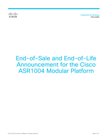
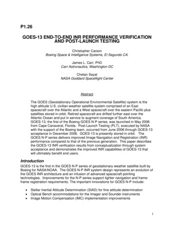
period IMC set is generated daily during eclipse season using a depth of eclipsecalibration table constructed from archived attitude profile solutions. A special post-flipIMC set is generated based on geometric symmetries between Imager and Sounder inthe case of a first flip, and based on archived attitude solutions in the case of asubsequent flip, to predict instrument thermal profile behavior in the first 24 hours after ayaw flip.Design and Initial Validation (PES & SFT)INR system-level verification began in the design phase using the PerformanceEvaluation System (PES), which is a high-fidelity event simulation of the full INR systemand a contract deliverable. PES models all INR events (star sightings, landmarkacquisitions, ranging, maneuvers, and ground operations) chronologically and includesembedded models of the Imager, Sounder, spacecraft attitude control and flightdynamics, and ground elements. PES error models matured during the course ofsystem development as subsystem performance characterizations matured, so did theircorresponding PES error models. Mixed-simulation testing with hardware in the loopwas performed during System Functional Testing (SFT). In SFT, the space segment isrepresented by the Boeing Satellite Emulator (BSE), which runs the flight software on aflight-like processor and includes time domain simulations of the Imager and Sounderand the flight dynamics. BSE telemetry is ingested by the Observation GenerationSoftware (OGS), which simulates the ground functions associated with detection ofstars, acquisition of landmarks, and ranging. The operational Orbit and AttitudeTracking System (OATS), upgraded for the GOES N-P series, receives and processesthe OGS data following standard INR operational protocols. SFT runs in real-time withthe INR control loop closing by commanding of the BSE through the operational GOESTelemetry Acquisition and Control System (GTACS).An effort was made to coordinate PES and SFT error models so that each crossvalidates the other. Figure 1-2 shows a navigation error time series from PES and acomparison between three Monte Carlo runs of the PES pure-simulation and acorresponding SFT run.5
SFTPES #1PES #2PES 25.024.222.715-min. 8.990-min. 6.817.7Figure 1-2. PES Navigation Error Time Series (top); SFT Run and 3 Monte Carlo PES RunsCompared (bottom) for Navigation, Frame-to-Frame (FFR), and Within Frame (WIFR) 3-σ ErrorMetricsLaunch and Orbit Raising (LOR) TestingOrbit raising, deployments, and bus functional checkout are all part of the LOR phase.The LOR phase was performed by Boeing at the NOAA Satellite Operations ControlCenter (SOCC) in Suitland, MD and consisted of an Orbit Raising period and In-OrbitTest period. During the In-Orbit Test period, which started upon reaching the handoverorbit, the major deployments (solar array, magnetometer boom, and Imager/Soundercovers) were performed, the spacecraft was slewed to an earth pointed orientation andoperations in Storage Mode and Normal Mode were demonstrated. The LOR phasewas completed by L 22 days, and an engineering handover to NASA was performed.Storage ModeSIAD contributions to INR performance were assessed during the Storage Mode portionof LOR. Accurate determination of HIRU Angular Random Walk (ARW) error was6
performed during a portion of Storage Mode operations when the spacecraft was inInertial Hold. The Boeing SIAD Characterization Tool was used to determine StarTracker and HIRU performance and estimation of HIRU Angular Random Walk (ARW)error. The SIAD Characterization Tool is described in more detail in the PLT PayloadActivation and Characterization section.Normal Mode EntryAt the conclusion of Storage Mode testing, the primary star tracker pair was poweredon, and the on-board “lost-in-space” algorithm was used to autonomously determinespacecraft inertial attitude and provide an estimate of star tracker alignments sufficientto identify stars in star tracker Full Field of View (FFOV) mode. At this point thespacecraft attitude determination method was switched from sun based attitudedetermination to stellar inertial attitude determination. An ephemeris defining thecurrent spacecraft orbit was uploaded to the on-board computer, and the spacecraftwas commanded into Normal Mode and commanded to slew from a sun pointed attitudeto an earth pointed attitude.Calibrations, Initializations, and Checkouts in Normal ModeDuring Normal Mode operations, initial calibrations and checkout of all three pairs ofStar Trackers are performed, a preliminary HIRU performance assessment wascompleted, and instruments and communications payloads were activated. GroundBased Orbit and Attitude Determination (OAD) and Momentum Dumping andStationkeeping algorithms were then initiated and confirmed to be operating correctly.Post Launch Test (PLT)Activation of the government furnished Imager, Sounder and SXI, INR activation,instrument calibrations, and detailed verification and characterization of spacecraft andinstrument performance are the major activities performed in PLT.During PLT, a dedicated period of time is allocated to Imager and Sounder outgassingas well as for bus characterization tests and instrument calibrations. This portion of thePLT is referred to as Payload Activation and Characterization Testing (ACT). TheImager and Sounder cooler covers were deployed at the end of their outgassing period.The critical portion of PLT, Systems Performance and Operational Testing (SPOT),included INR operations startup and spacecraft system operations initialization. OverallINR performance was assessed during SPOT as well as the ability to perform typicalseasonal activities, such as yaw flip and eclipse operations. Additionally, instrumentperformance trending occurred during this phase.7
Payload Activation and Characterization Testing (ACT)In addition to quiescent Imager and Sounder outgassing operations, early PayloadActivation and Characterization Testing comprised of five significant activities related toINR which were completed prior to starting normal daily operations. These activities aredescribed in the following paragraphs.Assessment of Spacecraft Contributions to the INR Budget Characterizationof spacecraft performance was executed to verify that the INR error contributionswere at expected levels. Characterization of dynamic interactions and finalalignment calibrations and tuning were performed on the Star Trackers.Star Tracker Fine Alignment and Kalman Filter Tuning Star Tracker FineAlignment (SFA) improves on the preliminary star tracker alignment that wasperformed during the LOR phase. The alignment process makes the STmeasurements from the calibrated tracker combination self-consistent, therebyallowing directed field-of-view (DFOV) operations and minimizing SIAD thrashing(an effect that occurs when the number of stars tracked by each tracker changes,causing the weighting between tracker misalignments to change and thereforethe attitude estimate). An additional collection period, for each tracker paircombination was used to collect star tracker residual telemetry, which is used bythe Kalman Filter Statistics calibration algorithm to compute updated values forthe SIAD Kalman Filter measurement variances, which tune Kalman Filterperformance. Figures 1-3 shows typical results displays generated by theBoeing SFA / KFS tool for Star Tracker Alignment and Kalman Filter tuning.Figure 1-3. Typical SFA / KFS Tool Displays for ST Alignment, Kalman Filter TuningStar Tracker and HIRU Performance Characterization An initial performanceestimate of the star tracker and HIRU was performed in the LOR phase. TheBoeing provided SIAD Characterization Tool was used to determine Star Trackerand HIRU performance. Star and Kalman filter residual telemetry over a selectedperiod was used as the input to the SIAD tool for calculating Star Tracker8
performance. The SIAD tool estimates High Spatial Frequency (HSF) and LowSpatial Frequency (LSF) errors and errors in knowledge of boresight separationbetween the two trackers, determines HSF and LSF error dependence on starmagnitude, and estimates Temporal Noise (TN) errors. Typical results of StarTracker performance monitoring calculations for HSF, LSF, and tracker-to-trackerboresight separation generated by the SIAD tool are shown in Figure 1-4.Figure 1-4. SIAD Characterization Tool Typical ST HSF and LSF Estimate ResultsCharacterization of the HIRU required two periods of data collection. Estimationof HIRU Angular Random Walk (ARW) error was performed while the spacecraftwas in storage mode and inertially held. Angular White Noise (AWN) errordetermination, which required high rate collection of raw angle data, wasperformed during Normal Mode operations. The SIAD tool estimated ARW andAWN by applying Power Spectrum Density (PSD) analysis to the collected HIRUraw gyro angle and time tagged data. Examples of ARW and AWN estimatesoutput by the SIAD tool are displayed in Figure 1-5.9
Figure 1-5. SIAD Characterization Tool Typical ARW and AWN ResultsDynamic Interaction Testing (DIT) The effect of various spacecraft disturbancesources on spacecraft bus and Instrument pointing was characterized in a seriesof Dynamic Interaction Tests (DITs). Each DIT characterized the effect of aspecific disturbance source on spacecraft pointing, rates, acceleration and jitter,estimated spacecraft bus attitude error telemetry, and Angular Velocity Sensor(AVS) data during and after the time during which the disturbance occurs. Thesetests included: SAD, XRP, SXI disturbance tests during which the SAD, XRP, and SXIare commanded to offsets which represent the full range of motionexpected during Normal Mode operations, and slews of SAD and XRP areperformed at various stepping rates to determine effect on spacecraftpointing and jitter SAD stutter stepping characterization tests which examined the effects ofa wide range of stutter stepping cadences to determine the optimal stutterstepping design to minimize bus and Instrument jitter RWA disturbance characterization tests which, in addition to measuringpointing and jitter due to nominal daily RWA operations, would temporarilymodify wheel speed biases in order to induce wheel speed zero crossingsand increase the daily range of wheel speeds; these tests characterizedthe disturbances due to wheel zero-speed crossings in the event 3-wheeloperations would become necessary and determined maximum wheelspeeds for which disturbances remain within acceptable levels10
Characterization of jitter and pointing errors during and immediatelyfollowing the daily momentum dump. Characterization of pointing and jitter during and immediately followingvarious types of Imager mirror motion and in the presence of filter wheeldisturbancesDIT results were compared against predicted / budgeted allocations fordisturbance induced pointing errors and jitter, and were used to determine overallspacecraft disturbance contributions to the INR budget.IMC and DMC Characterization Image Motion Compensation (IMC) andDynamic Motion Compensation (DMC) characterization occurred during thisphase of PLT. The error in the computation of the IMC is based on the Boeingprovided IMC/DMC tool. The tool collects telemetry of applied IMC signal andcompares it to a calculation of ideal IMC. The IMC/DMC tool also assesses themagnitude and phase difference between the Imager DMC output and the S/Cmotion sensed by an Angular Velocity Sensor (AVS). Examples of output fromIMC/DMC tool are provided in Figure 1-6.Figure 1-6. IMC/DMC Tool Typical Results11
System Performance and Operational Testing (SPOT)Evaluation of overall system performance during the course of typical day-to-dayoperations, as well as calibration and trending of INR performance occurred during theSPOT phase. Start up and calibration of the ground INR system initiates thisPerformance and Operational Testing period in which the majority of the PLT periodwas spent. Once INR startup and calibration was complete, determination of overallINR performance during normal operations began.The Performance and Operational Testing period encompassed INR performanceoperations through one eclipse season and a yaw flip sequence. Additionally, a numberof other spacecraft capabilities were tested including entry into and return from storagemode, as well as station change operations. These activities are described in moredetail below:INR Start Up & Calibration / Imager Boresight Alignment DeterminationINR Startup initiates the semi-closed loop process of using INR observation data(landmarks, stars, and S/C range) in the ground Orbit and Attitude TrackingSystem (OATS) to achieve knowledge and repeatability of the Imager andSounder attitude profiles and the spacecraft orbit from an initially unknownattitude state and an externally determined orbit state provided by the FlightDynamics group. Additionally, the mean Imager/Sounder boresight attituderelative to the Star Tracker Assembly is determined and removed in the groundsystem, effectively re-defining Imager and Sounder nadir.A characterization of the effect of star tracker attitude variations on Imagerinstrument attitude using Star Measurement Comparison tool developed byBoeing was also performed during this calibration period. This tool uses INRground system generated Imager instrument attitude information over the courseof a day and star tracker residual telemetry to provide comparison plots of startracker and instrument attitudes. Examples of output from Star MeasurementComparison tools are provided in Figure1-7.Figure 1-7. Star Measurement Comparison Tool Typical Results12
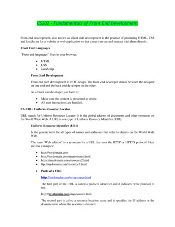
Other calibrations include assessing the optimal fit orders for each of the fiveattitude terms for the Imager and Sounder, the error associated with the OATSability to determine orbit using landmarks and S/C range information and theerror associated with the ground computed delta-V for all maneuvers.INR Spec Testing Evaluation of overall INR performance by NASA, using INRground system generated landmark residual based metrics as interpreted by thegovernment developed Performance Assessment System (PAS) occurred duringthe normal mode specification period, during Yaw Flip Operations, EclipseOperations and Stationkeeping and Station change maneuvers.Normal Operations Checkout INR system level performance was evaluated forall INR categories of navigation. The statistics were gathered during the periodbetween spacecraft stationkeeping maneuvers, where operations wereperformed based on a daily normal operations timeline. The performance wasmeasured as the percentage of observations that fell within the specification inthe given category. To meet the INR requirements 99.7% of the sample datahad to meet the requirement. GOES-13 met all of its observational requirementsfor the normal operations period as shown in Table 1-1. Figures 1-8, 1-9 and 110 show the landmark observations for the navigation, frame to frame and thewithin frame specifications for the entire 46 day specification testing period.Figure 1-11 shows the corresponding data from GOES-12 for the same dataspan. It is evident from Figures 1-8 and 1-11 that GOES-13 INR performance isimproved over 100% from that of GOES-12. The data collection period occurredduring eclipse season and thus eclipse data was excluded against themeasurement of normal operations specification compliance.NavigationFrame to FrameWithin Frame15 minsVisibleIR90 mins24 99.99%Performance100%Table 1-1 GOES-13 INR Normal Operations Specification Results13
Figure 1-8. GOES-13 INR Normal Operations Navigation Performance ResultsFigure 1-9. GOES-13 INR Normal Operations Frame to Frame Performance ResultsFigure 1-10. GOES-13 INR Normal Operations Within Frame Performance Results14
Figure 1-11. GOES-12 INR Normal Operations Navigation Performance ResultsSeasonal Yaw Flip During PLT GOES-13 operated through the autumnaleclipse period. In order to keep the sun on the –Y side of the spacecraft, a yawflip was performed immediately prior to the start of eclipse season. During theseperiods, as seen in Figures 1-12 and 1-13 imaging operations continued duringthe yaw flip recovery period and returned to full normal operations performancelevels following the recovery.Figure 1-12. GOES-13 INR Yaw Flip Operations 0 – 26 hrs Navigation Performance Results15
Figure 1-13. GOES-13 INR Yaw Flip Operations 26 – 50 hr Navigation Performance ResultsEclipse Operations During PLT GOES-13 operated through the autumnaleclipse period. During these periods, despite there being no operational INRrequirement for the first season, imaging operations continued during the eclipse.As seen in Figure 1-14 eclipse performance fell within operational specificationsfor eclipse.Figure 1-14. GOES-13 INR Eclipse Operations Navigation Performance ResultsStation Change (Drift) Checkout At the conclusion of the Normal OperationsSpecification testing, a station change maneuvers was executed to drift thespacecraft from 150 W to 135 W. As shown in Figure 1-15, performance duringthe drift period was well within normal mode specifications while drifting atapproximately 1 degree per day.16
Figure 1-15. GOES-13 INR Drift Operations Navigation Performance Results17
ConclusionsGOES-13 is the first spacecraft in the GOES NOP series representing an evolution ofthe heritage GOES INR architecture incorporating advanced spacecraft pointingtechnologies (SIAD, DMC, an optical bench, and an improved IMC implementation) andnew ground algorithms to support eclipse, thruster, and yaw-flip operations. Systemlevel INR verification began in the design phase using the high fidelity PES simulator,followed by hardware-in-the-loop testing in SFT, and finally concluded in flight duringPLT. Each verification step built confidence for the next step, and concluded with arobust spacecraft system that is ready for long-term operational service and complieswith all system level INR specifications. The GOES N-P generation delivers substantialimprovement in INR over the previous generation as evident from the very successfulPLT phase. PLT was an intensive effort lasting about six months. A thorough battery ofengineering and subsystems tests led up to INR specification testing, during which theentire system was operated as it would normally be in routine service. For all INRrequirements pertaining to normal operations, INR specification compliance greater than99.7% was achieved. The benefits of GOES-13 INR performance to the user communitywere demonstrated during the science testing portion of PLT. A side-by-side movieloop comparison between the legacy GOES system and GOES-13 is found te/2006/12. 1 This demonstration clearlyshows the enhanced quality of service that is available a higher percentage of theavailable mission time than ever before, thanks to the ability to operate through eclipsesand improved recovery after station-keeping maneuvers and yaw flips.1Tom Whittaker, CIMSS / SSEC, 12/200618
Eclipse and Yaw Flip IMC In a departure from GOES IM operations, the GOES-13 primary instruments remain powered on and providing service through eclipse. Additionally, GOES-13 has the ability to perform routine semi-annual yaw flips to decrease sun loading on the instrument radiative coolers. The GOudes new ground ES-13 INR system incl